MidNite Solar MNBE-B User manual

MNBE-B, D, D3R, E Instructions
Rev: A Page 1 of 10
Battery Enclosure
Installation Instructions
These instructions are for the assembly of
Midnite Solar Battery Enclosure models
MNBE-B, MNBE-D, MNBE-D3R and
MNBE-E
MNBE-D3R Shown

MNBE-B, D, D3R, E Instructions (continued)
Rev: A Page 2 of 10
IMPORTANT SAFETY INSTRUCTIONS
SAVE THESE INSTRUCTIONS - These instructions contain important safety and operating
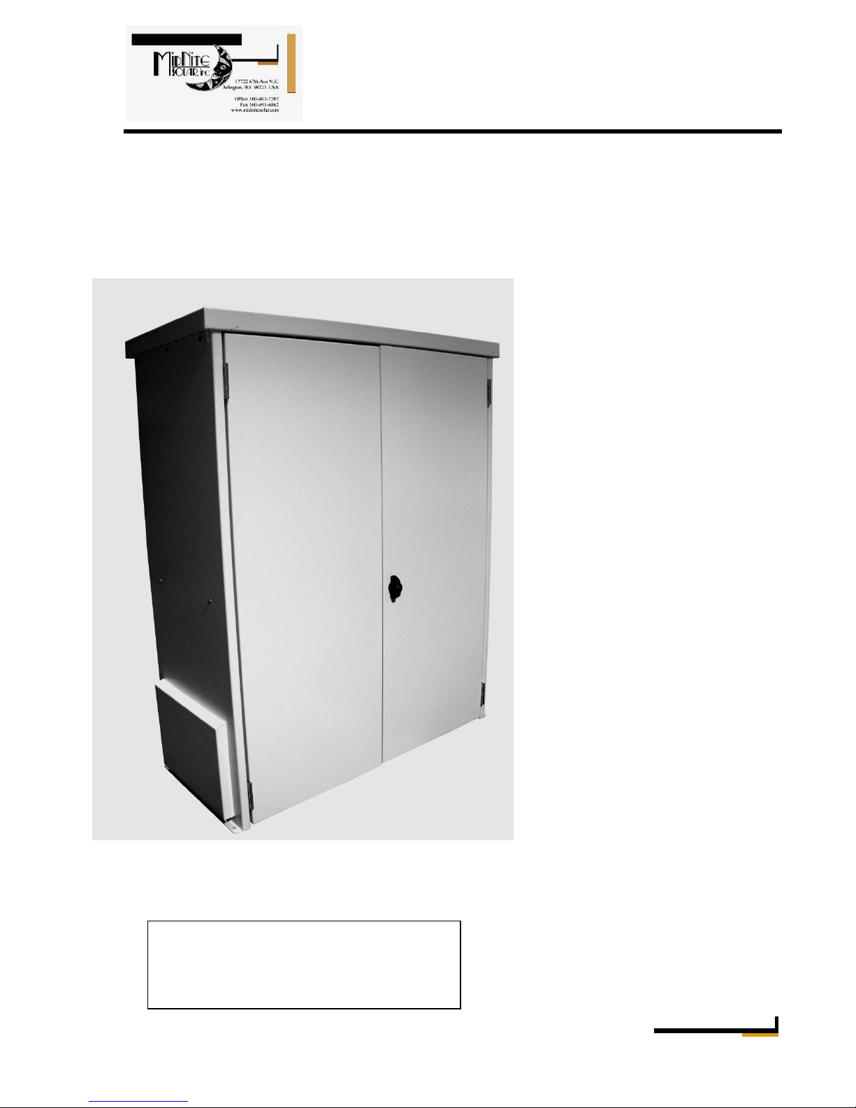
instructions for the MidNite Solar Battery Enclosure Size B, D, D3R and E for residential and
commercial applications.
If you do not fully understand any of the concepts, terminology, or hazards outlined in these
instructions, please refer installation to a qualified dealer, electrician or installer. These
instructions are not meant to be a complete explanation of a renewable energy system.
GENERAL PRECAUTIONS
WORKING WITH OR IN THE VICINITY OF A LEAD ACID BATTERY, SEALED OR
VENTED IS DANGEROUS. VENTED BATTERIES GENERATE EXPLOSIVE GASES
DURING NORMAL OPERATION. FOR THIS REASON, IT IS VERY IMPORTANT THAT
BEFORE SERVICING EQUIPMENT IN THE VICINITY OF LEAD-ACID BATTERIES,
YOU REVIEW AND FOLLOW THESE INSTRUCTIONS CAREFULLY.
If service or repair should become necessary, contact MidNite solar Inc. Improper servicing may
result in a risk of shock, fire or explosion. To reduce these risks, disconnect all wiring before
attempting any maintenance or cleaning. Turning off the inverter will not reduce these risks.
Solar modules produce power when exposed to light. When it is not possible to disconnect the
power coming from the Photovoltaics by an external means such as a combiner, cover the
modules with an opaque material before servicing any connected equipment.
Never attempt to charge a frozen battery.
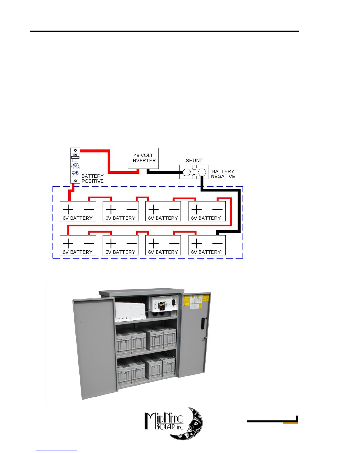
When it is necessary to remove a battery, make sure that the battery bank disconnect breaker is in
the off position and that the PV breakers, grid breakers and any other sources of power to the
inverter are in the off position. Then remove the negative terminal from the battery first.
To reduce risk of battery explosion follow these instructions and those published by the battery
manufacturer as well as the manufacturer of any additional equipment used in the vicinity of the
batteries. Before installing the battery enclosure, read all instructions and cautionary markings in
or on any connected electrical equipment.
Avoid producing sparks in the vicinity of the batteries when using vented batteries. Provide
ventilation to clear the area of explosive gases. Sealed AGM and Gel batteries do not under
normal conditions create explosive gases. Be especially cautious when using metal tools.
Dropping a metal tool onto batteries can short circuit them. The resulting spark can lead to
personal injury or damage to the equipment. Provide ventilation to outdoors from the battery
compartment when installing vented batteries such as golf cart T-105 batteries. The addition of a
spill tray is also a good idea.
Clean all battery terminals. Very high currents are drawn from the batteries; even a small amount
of electrical resistance can result in overheating, poor performance, premature failure or even
fire.

MNBE-B, D, D3R, E Instructions (continued)
Rev: A Page 3 of 10
Have plenty of fresh water and soap nearby in case battery acid contacts skin, clothing or eyes.
Wear complete eye and clothing protection. Always avoid touching eyes while working near
batteries. If battery acid or battery terminal corrosion contacts skin or clothing, wash
immediately with soap and water. If acid enters the eyes, immediately flood with cool running
water for at least 15 minutes and get medical attention immediately. Baking soda neutralizes
battery acid electrolyte. Keep a supply near the batteries.
Do not work alone. Someone should be in the range of your voice or close enough to come to
your aid when you work with or near electrical equipment.
Remove rings, bracelets, necklaces, watches etc. when working with batteries, photovoltaic
modules or other electrical equipment. Power from an illuminated photovoltaic array makes a
very effective arc welder with dire consequences if one of the welded pieces is on your person.
To reduce the risk of injury, connect only deep cycle lead acid type rechargeable batteries. Other
types of batteries may leak or burst, causing personal injury or damage.
Assembly Instructions
Hardware kit contents
Midnite PN
Description
MNBE-B
MNBE-D
MNBE-D3R
MNBE-E
3-089-1
Fan hole cover plate 1.75”
1
1
-
1
3-095-1
Fan hole cover plate GJ1
1
1
-
1
5-029-1
Midnite Solar Badge
1
1
1
1
6-006-1
10-32 X 3/8 Machine Screw
-
-
16
-
6-029-1
#10 X 3/8 Flat Head Screw
9
13
9
13
6-057-1
#6 X 3/8 Screw Type A 82○
25
25
25
25
6-088-1
#10 X 3/8 Screw Type B
40
40
21
40
9-052-1
Hinge
2 PKG (2)
2 PKG (2)
2 PKG (2)
2 PKG (2)
9-204-1
Keyed Handle
1
1
1
2
9-205-1
Pawl
1
1
1
1
9-213-1
Hole Plug
-
-
-
2
10-016-1
Assembly Instructions
1
1
1
1
Preparation:
You will require a #2 Philips screw driver and a 5/16” wrench to tighten screws, as well as a
slotted screw driver and hammer to remove knockouts.
Step 1:
Attach shelves to the two sides as shown below.
Use eight #10 x 3/8” sheet metal screws.
4 Screws per shelf. Bottom shelf is the floor of the unit.
Step 2:
#10 x 3/8” Stainless Steel
Hex head sheet metal screw

MNBE-B, D, D3R, E Instructions (continued)
Rev: A Page 4 of 10
Install eight #10 x 3/8” Flat head Philips SS sheet metal screws front and back to attach sides to
shelves. Additional shelves may be purchased to accommodate other configurations (Outdoor
units see step 4B).
Step 3:
Install the back panels. Both panels are identical. Make sure to orient them so that the knock outs
are located in the upper half of the panel. You will use #10 x 3/8” Hex head SS sheet metal
screws.
#10 x 3/8” Stainless Steel
Flat head sheet metal screw
Example of screw in Step 2
#10 x 3/8” Stainless Steel
Hex head sheet metal screw
Four of the screws shown from Step 3
Two screws attach under each shelf to the
backs from Step 3

MNBE-B, D, D3R, E Instructions (continued)
Rev: A Page 5 of 10
Step 4:
Attach the top using six #10 x 3/8” Hex head SS
sheet metal screws. Four on the sides and two to
the back covers. Orient the top such that the 2”
knockout is located to the rear of the enclosure.
MNBE-D3R does not have this 2” knockout,
This top has no front or back orientation.
Step 4A (MNBE-D3R Only)
The MNBE-D3R is supplied with weather stripping to be applied around the door opening top
and sides and also on the left door lip.
Step 4B (MNBE-D3R Only)
Install outer covers as shown using four 10-32 X 3/8 Machine Screws from the inside. This is
easier before the doors are installed. Run a bead of silicone sealant along the edge of the cover
before installation.
Note: Any components installed in knockouts must be rated for use with a NEMA 3R enclosure.
10-32 X 3/8 Machine Screw
Outer cover installed, Right side shown.
Left side is installed the same as the right.
#10 x 3/8” Stainless Steel
Hex head sheet metal screw
Cabinet lip
Lip of left door
Apply silicone sealant
from the inside to seal
corners of cover
Seal all unused openings on outdoor enclosures
Use 100% silicone (not included).
Behind doors

MNBE-B, D, D3R, E Instructions (continued)
Rev: A Page 6 of 10
Step 4C (MNBE-D3R Only)
Seal enclosure with silicone (use 100% silicone).
Run a bead of silicone sealant along the back panels to seal the back
Step 5:
Attach the left door
Each hinge will use three #6 x 3/8” Flat head screws to secure the hinge to the sides.
The screws supplied with the hinge are not used.
Note: The hinge side with three knuckles should be
mounted to the enclosure and the side with two
knuckles should be mounted to the door.

MNBE-B, D, D3R, E Instructions (continued)
Rev: A Page 7 of 10
Snug the screws up to the hinge, but do not over tighten.
Step 6:
Attach the left door using #6 flat head sheet metal screws The right door uses the same screws.
Left door has a lip as shown.
Step 7:
Assemble the lock in the double D hole as shown below.
Note: It may require a bit of adjustment on the cam in order to align with slot in the bottom of
shelf.
Lock Installed Lock shown latched Parts of lock assembly
Your Battery enclosure is now fully assembled.
Before placing batteries on shelves, make sure the enclosure is in its final location. It will be too
heavy to move once batteries are installed.
If batteries are to be strapped down, use the oblong holes at the ends of the shelves to go between
the top side and the bottom side of the shelf. The straps, (not supplied) need to be fed under the
bottom shelf prior to installing batteries.
#6 x 3/8” Stainless Steel
Flat head sheet metal screw

MNBE-B, D, D3R, E Instructions (continued)
Rev: A Page 8 of 10
The battery enclosure may be bolted down to the floor using the four holes located on the side
flanges. Mounting holes will accept up to 3/8” bolts. Use a thick, wide flat washer as a back up
underneath the bolt head to add to the pull through strength.
The MNBE-B is designed to hold 8 group 31 or group 27 batteries as well as T-105’s or 8
Concorde PVX 3050T(13” tall golf cart batteries).
With T-105’s MNDC250 (sealed) breaker
You must use sealed AGM or Gel batteries when installing a circuit breaker/disconnect in one of
the side panels as shown above. Circuit breakers make sparks and vented batteries cannot be in
the same cabinet with any device that makes arcs or sparks. A circuit breaker installed as shown
must be inserted in the battery positive lead. Do not install in the negative leg.
Two battery enclosures may be connected together side by side for additional storage. 2” conduit
knock outs are provided on each side of the enclosure to accommodate this configuration. Use a
6” long conduit to connect the two cabinets together.
Battery boxes stacked vertically on top of each other. ¾” pieces of wood are inserted inside the
top panel to support the extra weight and give a place to screw to.
Drainage:
The MNBE is designed to self drain if water enters the cabinet. The enclosure is not tightly
sealed at the bottom, however if the installation limits the self drain feature add drainage holes at
the bottom of the enclosure.
Ventilation:
The MNBE enclosures are designed for sealed batteries. Sealed batteries do not require
ventilation. When flooded batteries are used a spill tray must be provided (Not supplied) and
ventilation of explosive gasses must be directed out the top through the 2” knockout. The
NEMA-3R version does not have a knockout on the top and must be provided as part of the
installation. Powered ventilation may be required to provide proper ventilation.
¾” Piece of wood added as support

MNBE-B, D, D3R, E Instructions (continued)
Rev: A Page 9 of 10
Battery Configuration:
The MNBE-B is designed for eight batteries. The following diagrams show three different ways
to configure the battery bank. This is not meant to show all methods of inter-connecting the
battery bank. It is the installer’s responsibility to ensure that all wiring conforms to NEC
ANSI/NFPA 70 and all local codes.
This configuration shows a 24 volt hook up using 12 volt group 31 batteries. Notice that in this
configuration there are 4 parallel strings. Parallel strings can be a problem when too many are
involved in cyclic applications such as in an off-grid installation. This set up poses no problems
in a power back up application where batteries are normally floated. In an off-grid home, this
battery bank would not be large enough for acceptable performance. You could add a couple
more battery enclosures side by side, but the quantity of paralleled strings using these 12 volt
batteries would be excessive. It would be advisable to go to 6 volt golf cart sized batteries to cut
the paralleled strings in half.

MNBE-B, D, D3R, E Instructions (continued)
Rev: A Page 10 of 10
Midnite Solar
17722 – 67Th Ave Ne
Arlington, Wa 98223 USA
Ph 360-403-7207
Fax 360-691-6862
This configuration utilizes the same 12 volt group 31 batteries, but hooked up for 48 volts. There
are only 2 paralleled strings in this system. A second battery enclosure may be installed side by
side or on top of each other for double the capacity.
Rumors persist in the industry that the higher voltage battery banks will not supply as much
power as a low (12V) bank. This is simply not true. Take 8 group 31 batteries. Each battery is
rated at 105 amp hours at 12 volts. Each battery is thus good for 1260 watt hours. Eight of these
batteries yields 10,080 watt hours. No matter how these batteries are configured, they will still be
the same watt hour battery bank. Be careful when looking at “amp hour” ratings. You also need
to consider the voltage. Volts times amp hours yields watt hours. This 10,080 watt hour battery
bank conceivably could run a 10,000 watt light bulb for 1 hour or a 1 watt light bulb for 10,000
hours. In power back up applications, count on using up 80% of the watt hour rating. In cyclic
applications you should not go lower than 50% depth of discharge.
This configuration uses 6 volt sealed batteries that result in only one string.
This is a 48 volt battery bank. You could add 3 more cabinets and have only 4 paralleled strings.
MNBE-D With three shelves, Eight sealed
batteries, Inverter and disconnects.
This manual suits for next models
3
Table of contents
Other MidNite Solar Enclosure manuals

MidNite Solar
MidNite Solar Barcelona Breaker Box User manual

MidNite Solar
MidNite Solar MNPV3 Reference guide

MidNite Solar
MidNite Solar MNPV6 Reference guide

MidNite Solar
MidNite Solar MND3RACCPLME User manual

MidNite Solar
MidNite Solar MNBE-A User manual

MidNite Solar
MidNite Solar MNBE-8D2x2 User manual