SECTION A-A
SCALE 1:10
DETAIL B
SCALE 1:3
ISOMETRIC VIEW
SCALE 1:25
A
A
B
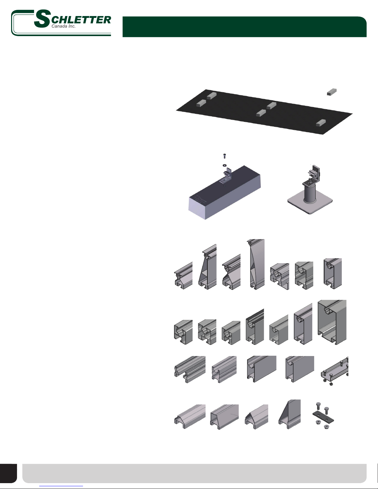
PARTS LIST
DESCRIPTIONPART NUMBERITEM
Block, Ballast, Fix-EZ, Concrete, with Angle, Kit169015-0009
Rail, FixZ-7, Front, Custom
121002-0011
Splice, FixZ-7, Front, Internal, Kit
129071-0002
Rail, FixZ-7, Rear, Custom121001-0016
Splice, FixZ-7, Rear, Internal, Kit129070-000
7
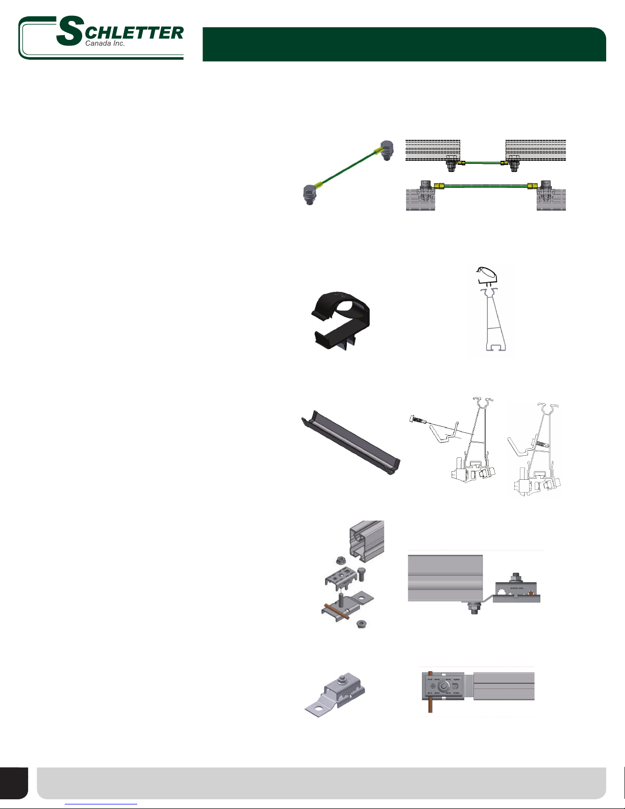
End Clamp, Rapid5K, Grounding, 46mm
135007-14611
Middle Clamp, Rapid5K, Grounding, 40-50mm
135002-00612
1
A
2345678 9 10 11 12 13 14 15 16 17
B
C
D
E
F
G
H
I
J
K
12 3 54 678 9 10 11 12 13 14 15 16 17
A
B
C
D
E
F
I
J
NO. DRAWN: CHECKED: REVIEWED: APPROVED: REVISIONS: Drawing Number:
Sloped Roof Standard FixEZ-7
Standard Racking Structure
Dimensions and Specifications v.01
JOB NUMBER:
SHEET: 1 OF 1
SCALE:
SEE DRAWING VIEWS
ISSUED BY: SCHLETTER INC.
PROPRIETARY AND CONFIDENTIAL
Client: Project Site:
Ballast Block
PRELIMINARY
AND SEALED BY A LICENSED
UNLESS THIS DRAWING IS SIGNED
A PRELIMINARY DESIGN AND SHALL
STRUCTURAL ENGINEER, IT IS
NOT BE USED FOR CONSTRUCTION.
v
0
New Drawing
1001 COMMERCE CENTER DR. | SHELBY, NC 28150
TEL: (704) 595 - 4200 | Fax: ( 704) 595 - 4210
EMAIL: MAIL@SCHLETTER.US
WWW.SCHLETTER.US
DESIGN CRITERIA:
2012 EDITION OF THE INTERNATIONAL BUILDING CODE, WITH LOCAL AMENDMENTS.
LOADS:
MODULE DEAD LOAD = 48 LBS PER MODULE
SNOW LOAD = 0 PSF
WIND DESIGN:
DESIGN BASED UPON WIND TUNNEL TEST REPORT # RC 1665/0513-e
BASIC WIND SPEED = 115 MPH (3 SECOND GUST).
EXPOSURE: C
RISK CATEGORY = II
NOTE:
OWNER MUST VERIFY WITH PROFESSIONAL ENGINEER THAT ROOF STRUCTURE AND ITS
COMPONENTS CAN SUPPORT AND TRANSFER POINT LOADS AT EACH CONNECTION LOCATION
RESULTING FROM ADDITION OF SOLAR PANELS AND RACKING. SEE TABLE BELOW
GENERAL:
1. THE STRUCTURAL CONSTRUCTION DOCUMENTS REPRESENT THE FINISHED STRUCTURE.
THEY DONOT INDICATE THE METHOD OR SEQUENCE OF CONSTRUCTION. THE
CONTRACTOR SHALL BE RESPONSIBLE FOR AND PROVIDE ALL MEASURES NECESSARY TO
PROTECT THE STRUCTURE DURING CONSTRUCTION. SUCH MEASURES SHALL INCLUDE,
BUT NOT BE LIMITED TO, BRACING, SHORING FOR LOADS DUE TO CONSTRUCTION
EQUIPMENT, ETC. THE STRUCTURAL ENGINEER SHALL NOT BE RESPONSIBLE FOR THE
CONTRACTOR'S MEANS, METHODS, TECHNIQUES, SEQUENCES FOR PROCEDURE OF
CONSTRUCTION, OR THE SAFETY PRECAUTIONS AND THE PROGRAMS INCIDENT THERE TO
(NOR SHALL OBSERVATION VISITS TO THE SITE INCLUDE INSPECTION OF THESE
ITEMS). THE CONTRACTOR SHALL BE RESPONSIBLE FOR THE DESIGN AND
IMPLEMENTATION OF ALL SCAFFOLDING, BRACING AND SHORING.
2. WHERE REFERENCE IS MADE TO VARIOUS TEST STANDARDS FOR MATERIALS, SUCH
STANDARDS SHALL BE THE LATEST EDITION AND/OR ADDENDA.
ALUMINUM:
1. ALL ALUMINUM SHALL CONFORM WITH THE LATEST ALUMINUM DESIGN HANDBOOK.
2. ALL ALUMINUM SECTIONS SHALL BE:
a. SEMI-HOLLOWS AND HOLLOWS SHALL BE 6105-T5, 6005A-T6, OR 6005-T5
b. SOLIDS SHALL BE 6063-T6
STEEL:
1: ALL BOLTS AND WASHERS SHALL BE 304 STAINLESS STEEL CLASS 2 (A2-70).
2. ALL NUTS SHALL BE 316 STAINLESS STEEL CLASS 2 (A4-70).
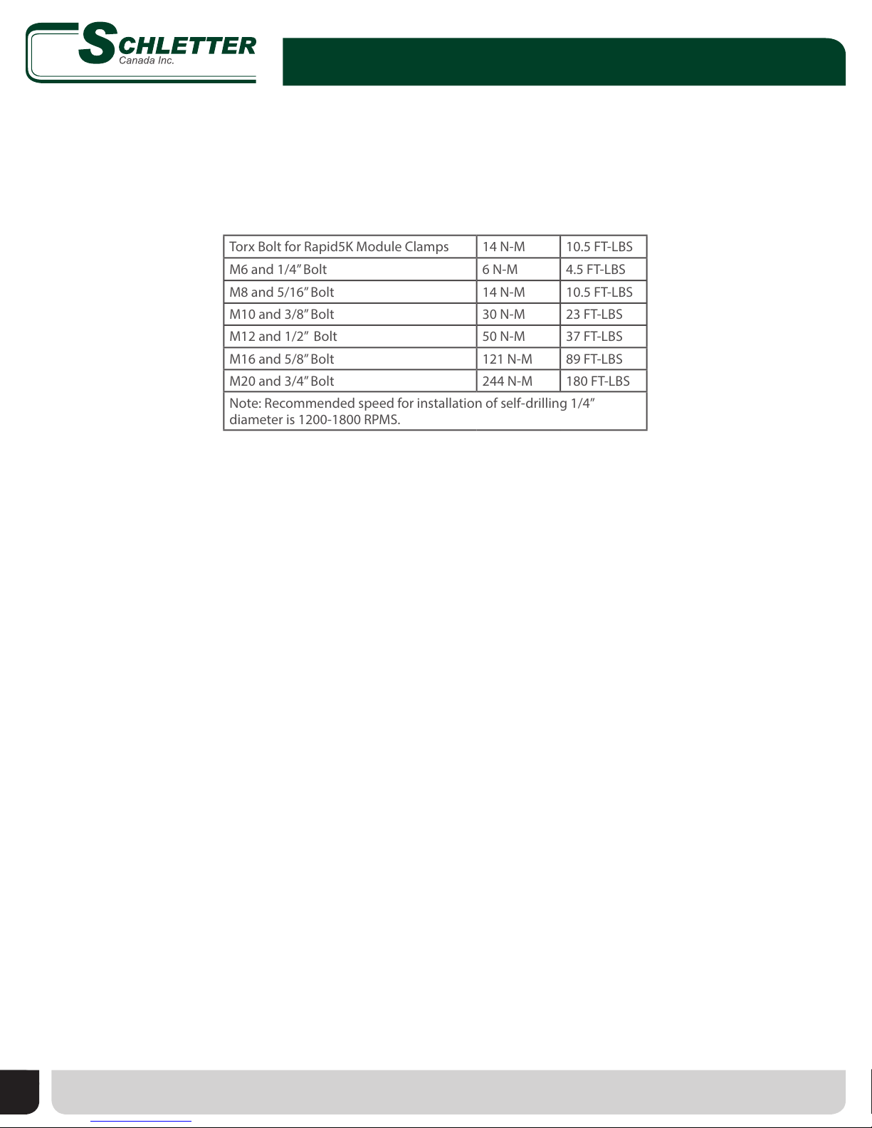
TORQUE:
TORX BOLT FOR RAPID 2+ MODULE CLAMPS IS 14 N-M (10.5 FT-LBS)
M6 AND 1/4" BOLT TORQUE IS 6 N-M (4.5 FT-LBS)
M8 AND 5/16" BOLT TORQUE IS 14 N-M (10.5 FT-LBS)
M10 AND 3/8" BOLT TORQUE IS 30 N-M (23 FT-LBS)
M12 AND 1/2" BOLT TORQUE IS 50 N-M (37 FT-LBS)
M16 AND 5/8" BOLT TORQUE IS 121 N-M (89 FT-LBS)
M20 AND 3/4" BOLT TORQUE IS 244 N-M (180 FT-LBS)
NOTE: RECOMMENDED SPEED FOR INSTALLATION OF SELF-DRILLING 1/4" DIAMETER
SCREWS IS 1200-1800 RPMS.
MODULE SIZE:
RACKING SYSTEM DESIGNED FOR MODULE SIZE: 1600mm x 990mm x 50mm
VERTICAL MODULE GAP: 23 mm
HORIZONTAL MODULE GAP: 5 mm
NOTE:
1. TOTAL RAIL LENGTH NOT TO EXCEED 50 FT WITHOUT EXPANSION JOINT OR PHYSICAL BREAK.
2. SEE LAYOUT FOR MID SPAN SUPPORT LOCATIONS.
3. TO TRANSITION BETWEEN COLOR CODED BALLAST ZONES ONE FULL BALLAST BLOCK
OF A CLOSER SPACING MUST BE CARRIED INTO AN ADJACENT ZONE WITH A GREATER
BALLAST BLOCK SPACING
4. SPLICE CANNOT BE LOCATED ALONG THE LENGTH OF THE CANTILEVER NOR WITHIN 25% OF THE
SPAN LENGTH'S DISTANCE OF AN END SUPPORT AND MUST FALL BETWEEN SUPPORTS.
5. MINIMUM FRICTION COEFFICIENT BETWEEN ROOF AND BALLAST BLOCK IS TOBE 0.42.
VARIES
990 [39 in] TYP
VARIES SPAN TO BE REPEATED FOR LONGER ARRAYS
BASED ON ZONE LAYOUT (SEE NOTES)
VARIES
397[15
5
8
in]
397[15
5
8
in]1191[46
7
8
in]
1985[78
1
8
in]TYP
2500 [98 7
16 in] TYP SHADING DISTANCE
353 [13
7
8
in]
4°
397 [155
8in] 1197 [471
8in] 1303 [51 5
16 in] 1197 [471
8in] 390 [153
8in]
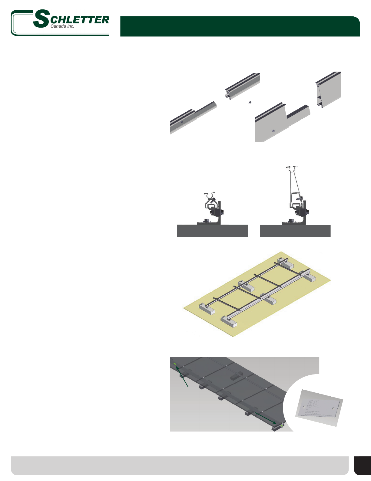
FIXZ-7 FRONT SPLICE DETAIL
SCALE 1 : 5
FIXZ - 7 FRONT RAIL
FIXZ - 7 FRONT SPLICE
FIXZ-7 FRONT RAIL
FIXZ-7 REAR SPLICE DETAIL
SCALE 1 : 5
FIXZ - 7 REAR RAIL
FIXZ - 7 REAR SPLICE
FIXZ - 7 REAR RAIL
FIXZ-7 FRONT EXPANSION JOINT
SCALE 1 : 5
FIXZ-7 FRONT RAIL
FIXZ-7 FRONT SPLICE
(SCREWS ON SAME SIDE)
1" EXPANSION JOINT
BETWEEN RAILS
FIXZ-7 FRONT RAIL
MODULE END CLAMP MODULE END CLAMP
FIXZ-7 REAR EXPANSION JOINT
SCALE 1 : 5
FIXZ-7 REAR RAIL
FIXZ-7 REAR SPLICE
(SCREWS ON SAME SIDE)
1" EXPANSION JOINT
BETWEEN RAILS
FIXZ-7 REAR RAIL
MODULE END CLAMP
MODULE END CLAMP
9
1
12
2
11
6
7
Fix-EZ™ Installation Manual
2/12 MI-018CA
072216
© Schletter Canada Inc. • 3181 Devon Drive • Windsor, Ontario N8X 4L3 • Tel: (519) 946 – 3800 • Fax: (519) 946 – 3805
E-mail: mail@schletter.ca • www.schletter.ca
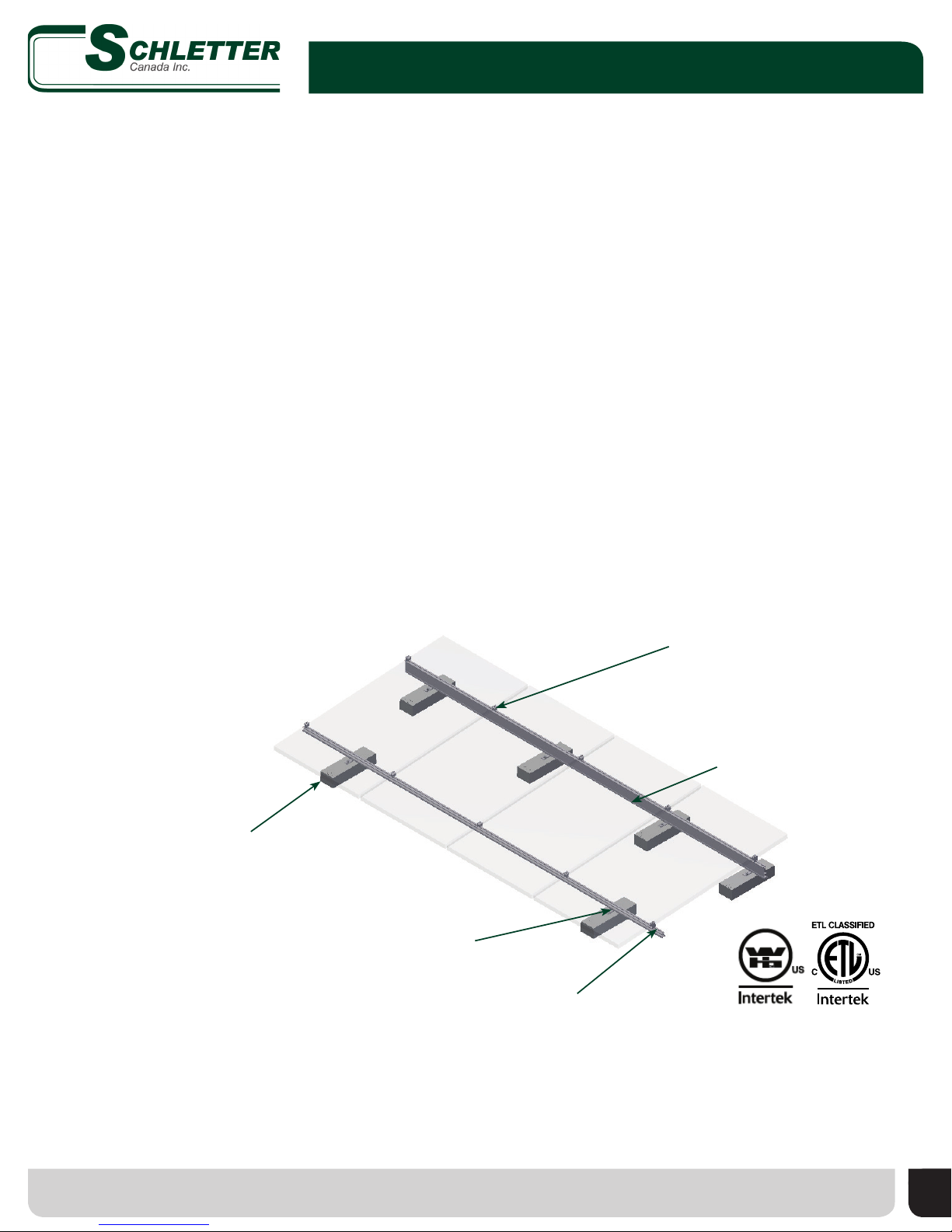
Sample Drawings
Specic drawings are provided for each project. Key information included on these drawings is as follows:
1. Design Criteria
2. Notes Section
3. Module Dimensions
4. Array Tilt
5. Array Dimensions
6. Ballast Block Spacing
7. Ballast Loads
2
1
3
6
SAMPLE DRAWING ONLY
Row and Ballast Specications
Provided in drawings are locations for ballast blocks and row spacing. Ballast blocks are positioned based on module
manufacturer’s connection specications. Row distance is determined based on shading distance. Ballast requirements and
support spacing will vary. See system/project specic drawings and calculations.
distance according to module height rows according to shading distance
4
5
6
3
7