MidNite Solar MN5048DIY User manual

2 of 3910-539-1 MN5048DIY REV -MN5048DIYUser Manual
Important safety instructionsPlease keep this manual for future use.The MNS Hybrid Inverter System is an all-in-one solution for 120 volt AC production, battery chargingfrom the AC input and a built-in MPPT PV Charge ControllerThis manual contains all safety, installation and operating instructions for the MNS Hybrid Inverter.Please read all instructions and precautions in the manual carefully before installation and use.ØHigh voltages exist inside the MNS Hybrid Inverter. To avoid personal injury, users shall not disassemble theMNS Hybrid Inverter themselves. Contact our Midnite Solar technical support department if the unit is a need for repair.ØDo not install the MNS Hybrid Inverter in harsh environments such as moist, oily, flammable, explosive, or heavilydusty areas. The unit is not rain-proof, do not install outside unless under cover where it will not be exposed to rain.ØThe mains input and AC output are high AC voltage, do not touch the wiring terminals.ØThe housing of the MNS Hybrid Inverter is hot when it is operating especially under full load.The exposed heatsink may be very hot, do not touch.ØDo not open the terminal protective cover when the MNS Hybrid Inverter is operating.ØIt is necessary to install a proper external circuit breaker on the 120V AC in and PV in connections.The unit has an internal circuit breaker on the 120V AC in but an external circuit breaker is required in addition. ØAlways turn off all combiners and AC circuit breakers of the PV array, AC mains & battery before installingand/or adjusting the wiring of the MNS Hybrid Inverter.ØAfter installation, check that all wire connections are tight to avoid terminal heating due to poor anda loose connection, which is dangerous and may cause fires.ØThe MNS Hybrid Inverter is for off-grid only. DO NOT Connect the AC OUTPUT to any source of ACincluding GRID and GENERATOR.

3 of 3910-539-1 MN5048DIY REV -MN5048DIYUser ManualCONTENTS 1. GENERAL INFORMATION ............................................................................................................. 4 1.1
PRODUCT OVERVIEW AND FEATURES
................................................................................................... 4 1.2 BASIC SYSTEM INTRODUCTION ........................................................................................................... 5 1.3 APPEARANCE ................................................................................................................................. 6 2. INSTALLATION INSTRUCTIONS .................................................................................................... 7 2.1 INSTALLATION PRECAUTIONS ............................................................................................................. 7 2.2 WIRING SPECIFICATIONSAND CIRCUIT BREAKER SELECTION
................................
...................................... 8 2.3
INSTALLATION AND WIRING
............................................................................................................. 11 3. OPERATING MODES .................................................................................................................. 17 3.1 CHARGING MODE ......................................................................................................................... 17 3.2 OUTPUT MODE ............................................................................................................................. 18 4. LCD SCREEN OPERATING INSTRUCTIONS ................................................................................... 19 4.1 OPERATION AND DISPLAY PANEL ..................................................................................................... 19 4.2 SETUP PARAMETERS DESCRIPTION
................................
................................................................... 22 4.3 BATTERY TYPE PARAMETERS.
................................
........................................................................... 28 5. OTHER FUNCTIONS ................................................................................................................... 29 5.1 DRY NODE ................................................................................................................................... 30 5.2 USB COMMUNICATION PORT
................................
.......................................................................... 30 6. PROTECTION ............................................................................................................................ 31 6.1 PROTECTIONS PROVIDED
................................
................................................................................ 31 6.2 FAULT CODE MEANING
................................
................................................................................... 33 6.3 TROUBLESHOOTING ............................... ....................................................................................... 34 7. SYSTEM MAINTENANCE ............................................................................................................ 35 8. TECHNICAL PARAMETERS ......................................................................................................... 36 9. WARRANTY ..................... ......................................................................................................... 39

4 of 3910-539-1 MN5048DIY REV -MN5048DIYUser Manual
1. General information 1.1 Product overview and features --
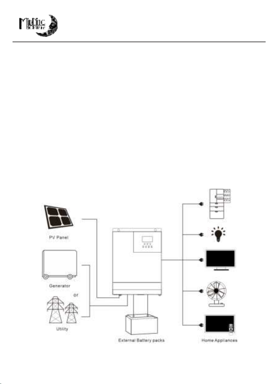
DIY series is a new all-in-one hybrid solar charger/inverter, which integrates battery MPPT solar & AC input charging with sine wave output. Thanks to DSP control and advanced control algorithm, it has fast response speed, high reliability and high industrial standards. Four charging modes are available, i.e. Only Solar, Mains Priority, Solar Priority and Mains & Solar hybrid charging; and two output modes are available, i.e. Inverter and Mains, to meet different application requirements. The solar charging module applies the latest optimized MPPT technology to quickly track the maximum power point of the PV array in any environment and obtain the maximum energy of the solar panel in real time. Through a state of the art control algorithm, the AC-DC charging module realizes fully digital voltage and current double closed loop control, with high control precision in a small volume. Wide AC voltage input range and complete input/output protections are designed for stable and reliable battery charging and protection. Based on full-digital intelligent design, the DC-AC inverter module employs advanced SPWM technology and outputs pure sine wave to convert DC into AC. It is ideal for AC loads such as household appliances, power tools, industrial equipment, and electronic audio and video equipment. The product comes with a segment LCD display design which allows real-time display of the operating data and status of the system. Comprehensive electronic protections keep the entire system safer and more stable. Features: 1. Full digital voltage and current double closed loop control, advanced SPWM technology, pure sine wave output.
2. Two output modes: mains bypass and inverter output; uninterrupted power supply.
3. Available in 4 charging modes: Only Solar, Mains Priority, Solar Priority and Mains & Solar hybrid charging.
4. Advanced MPPT technology with an efficiency of 99%.
5. Designed with a LCD screen and 3 LED indicators for dynamic display of system data and operating status.
6. ON/OFF rocker switch for AC output control.
7. Power saving mode available to reduce no-load loss.
8. Intelligent variable speed fan to efficiently dissipate heat and extend system life.
9. Battery charging using PV solar or AC input, supporting use of lead-acid and lithium battery technologies.
10. 360 ° all-round protection with a number of protection functions.
11. Complete protections, including short circuit protection, over voltage and under voltage protection, overload protection, reverse protection, etc.

5 of 3910-539-1 MN5048DIY REV -MN5048DIYUser Manual
1.2 Basic system introductionThe figure below shows the system application scenario of this product.A complete system consists of the following parts:1. PV module: Converts light energy into DC power, and charges the battery through the onboard MPPT solar charge controller, or to directly drive the inverter making AC power to drive the loads. (battery-less mode)2. Mains or generator: Connected at the AC input, to power the loads while charging the battery. If the mains or generator is not connected, the system can also operate normally, and the load is powered by the battery and PV array.3. Battery: Provided to ensure normal power supply to the system loads when solar energy is insufficient and the AC Main is not connected.4. Household load: Allow connection of various household and office loads, including refrigerators, lamps, TVs, fans and air conditioners.5. MNS Hybrid Inverter: The energy conversion unit of the whole system. Specific system wiring method depends on the actual application scenario.

6 of 3910-539-1 MN5048DIY REV -MN5048DIYUser Manual 1.3 Appearance ① Overload protector ⑨ Dry contact port ② ON/OFF rocker switch ⑩ Cooling fan ③ AC input port ⑪ Battery port ④ AC output port ⑫ Cooling fan ⑤ Grounding screw hold ⑬ PV port ⑥ RS485-2/CAN communication port ⑭ Touch the key lightly ⑦ USB communication port ⑮ Indicator light ⑧ RS485-1 communication port ⑯ LCD screen

7 of 3910-539-1 MN5048DIY REV -MN5048DIYUser Manual2. Installation Instructions2.1 Installation precautions Be very careful when installing the battery. Wear safety glasses when➣installing a lead-acid flooded battery. If you come into contact with thebattery acid, rinse with clean water immediately. Do not place metal objects near the battery to prevent short-circuit of the➣battery terminals. Hydrogen gas may be generated when the battery is charging. Please ensure \➣good ventilation. When installing the unit, be sure to leave enough space around➣the MNS Hybrid Inverter for proper heat dissipation. Do not install theMNS Hybrid Inverter and lead-acid battery(s) in the same cabinet to avoidcorrosion by sulfuric acid gas generated during battery operation. Only batteries that meet the requirements of the MNS Hybrid Inverter can➣be charged. Poorly connected connections and corroded wires may cause terminal heating➣which could melt the wire insulation, burn the surrounding materials, andeven cause fires. So, make sure the terminals have been tightened, andthe wires are secured with ties to avoid loose connections caused by shakingof wires during mobile applications. Avoid mounting in direct sunlight and where rainwater may get inside➣if mounting outside.. Even after the power is turned off, there is still high voltage inside the unit.➣Do not open or touch the internal components, and avoid related operationsuntil the capacitor completely discharges. Do not install the MNS Hybrid Inverter in harsh environments such as➣moist, oily, flammable or explosive, or heavily dusty areas. Do NOT reverse polarity at the battery input terminals, otherwise it may➣damage the device and/or cause a fire. The mains AC input and AC output are high voltage, so please do not touch➣the wiring terminals. Keep fingers and tools away from the fan, do not touch it to prevent injury.➣

8 of 3910-539-1 MN5048DIY REV -MN5048DIYUser Manual 2.2 Wiring specifications and circuit breaker selection Wiring and installation must comply with national and local electrical codes.Recommended PV array wiring specifications and circuit breaker selec t ion: Since the output current of the PV array is affected by the type, connection method and illumination angle of the PV module, the minimum wire diameter of the PV array is calculated according to its sho r t circuit current; refer to the short-circuit current value in the PV module specification (the sh o r t-circuit current is constant when the PV modules are connected in series; the short -circuit current is the sum of the short circuit currents of all PV modules connected in parallel); the sho r t circuit current of the PV array shall not exceed the maximum input current. - ➣ Refer to the table below for PV input wire diameter and switch: Models Recommended PV wiring diameter Maximum PV input current Recommendedcircuit breaker type MN5048DIY 10 AWG18A MNEPV20 or MNEDC20 Note: The voltage in series shall not exceed the maximum PV input open circuit voltage.

9 of 3910-539-1 MN5048DIY REV -MN5048DIYUser Manual ➣ Refer to the table below for recommended AC input wire diameter and switch: Models Recommended AC input wiring diameter Maximum bypass input current Recommendedcircuit breaker type MN5048DIY 6 AWG 63A MNEAC60 Note: There is already an appropriate circuit breaker at the Mains input wiring terminal,s oit is not necessary to add one more. ➣ Recommended battery input wire diameter and switch selection Models Recommended battery wiring diameter Rated battery discharge current Maximum charge current Recommended circuit breaker type MN5048DIY 2 AWG 125A 80A MNEDC125

10 of 3910-539-1 MN5048DIY REV -MN5048DIYUser Manual ➣ Recommended AC output wiring specifications and circuit breaker selection Models Recommended AC output wiring diameter Rated inverter AC output current Maximum bypass output current Recommendedcircuit breaker type MN5048DIY 6 AWG42A 63A MNEAC60Note: The wire gauge is for reference only. If the distance between the PV array and theMNS Hybrid Inverter or the distance between the MNS Hybrid Inverter and the battery isrelatively long, using a bigger gauge wire can reduce the voltage drop to improve systemperformance.Note: The above are only recommended wire gauge and circuit breaker. Please select the appropriate wiregauge and circuit breaker according to actual installation requirements. Note: Breakers are there to protect the wire not the electronics. Select wire size for the application, and thenselect breakers for the wire size.All MidNite Solar breakers are rated for continuous duty.
Recommended wire gauge and breaker size. Max Current Wire gauge and breaker size Recommended MidNite Breaker 20 Amps 12 AWG – 20 Amp Breaker MNEDC20 MNEPV20 25 Amps 10 AWG – 30 Amp Breaker MNEDC30 MNEPV30 30 Amps 10 AWG – 30 Amp Breaker MNEDC30 MNEPV30 40 Amps 8 AWG – 50 Amp Breaker MNEDC40 MNEPV40 50 Amps 8 AWG – 50 Amp Breaker MNEDC50 MNEPV50 60 Amps 6 AWG – 60 Amp Breaker MNEDC60 MNEPV60 125 Amps 2 AWG – 125 Amp Breaker MNEDC125 - MNEPV Breakers are dinrail mount and fit in the MNDC125 enclosure.

11 of 3910-539-1 MN5048DIY REV -MN5048DIYUser Manual 2.13 Installation and wiringInstallation steps:Step 1: Determine the installation position and the space for heat dissipation. Determine the installation positionof the MNS Hybrid Inverter, such as wall surface; when installing the MNS Hybrid Inverter, ensure that there isenough air flowing through the heat sink, and space of at least 200mm/8 inches to the left and right air outlets ofthe inverter are open to ensure natural convection heat dissipation. Refer to the installation diagram of the unit asabove.Warning: Danger of explosion! Never install the MNS Hybrid Inverter and lead-acid batteries in the sameconfined space! Also do not install in a confined place where battery gas may collect.

12 of 3910-539-1 MN5048DIY REV -MN5048DIYUser Manual Step 2: Remove the terminal cover Step3: Wiring ① Prior to AC input/output wiring, disconnect the external circuit breakerand confirm that the wire used is the appropriate AWG. Pleaserefer to Section 2.2 on pg. 8 “Wiring Specifications and Circuit BreakerSelection”.②ProperlyconnecttheACinputwireaccordingtothewiresequenceandterminalpositionshownintheigureonthenextpage.Pleaseconnectthegroundwireirst,andthenthehotwireandthentheneutralwire.AC input / output wiring method:

13 of 3910-539-1 MN5048DIY REV -MN5048DIYUser Manual :Ground L:Live N:Neutral ③ Properly connect the AC output wire according to the wire sequence and terminal position shown in the figure below. Please connect the ground wire first, and then the hot wire and the neutral wire. The ground wire is connected to the grounding screw hole on the cabinet using a ring terminal or copper lug. :Ground L:Live N:Neutral Note: The grounding wire shall be as large as possible (Not less than 10 AWG).The grounding pointshall be as close as possible to the MNS Hybrid InverterThe shorter the grounding wire, the better.

14 of 3910-539-1 MN5048DIY REV -MN5048DIYUser Manual PV input wiring method: PV+: PV input positive pole PV-: PV input negative pole ① Prior to wiring, disconnect the external circuit breaker and confirmthat the wire used is appropriate AWG. Please refer to Section 2.2“Wiring Specifications and Circuit Breaker Selection”;② Properly connect the PV input wire according to the wiresequence and terminal posion shown in the figure below.BATTERY wiring:① Prior to wiring, disconnect the external circuit breaker and confirmthat the wire used is appropriate AWG. Please refer to Section 2.2“Wiring Specifications and Circuit Breaker Selection”. The BAT wireneeds to be connected to the MNS Hybrid Inverter using a copper ringterminal either setscrew or crimp type is acceptable. Insure the crimp istight if using crimp style to prevent excessive heat generation caused byexcessive contact resistance from a loose terminal;② Properly connect the BAT wire according to the wire sequenceand terminal position shown in the figure on the next page.

15 of 3910-539-1 MN5048DIY REV -MN5048DIYUser Manual BAT +: Battery positive electrode BAT-: Battery negative electrode Warnings:① Mains input, AC output and PV array are all high voltage. So, before wiring,be sure to disconnect the appropriate circuit breaker.② Be very careful during DC wiring; do not close the circuit breaker duringwiring, and ensure that the “+” and “-” pole leads of each component areconnected properly; a circuit breaker must be installed at the battery inputterminals. Refer to Section 2.2 on pg. 9 “Wiring Specifications and Circuit BreakerSelection” to select a correct circuit breaker. Before wiring, be sure todisconnect the circuit breaker to prevent strong electric sparks and avoidbattery short circuit; if the MNS Hybrid Inverter is used in an area withfrequent lightning, it is recommended to install an external surgesuppressors at the PV input terminal as well as the AC input and output.The MNSPD300DC is the correct model for the PV input and theMNSPD300AC for the AC input and output. Both sold separatelyStep 4: Check if the wiring is correct and tight. In particular, check if thebattery polarity is reversed, if the PV input polarity is reversed and if the ACinput is properly connected.

16 of 3910-539-1 MN5048DIY REV -MN5048DIYUser Manual Step 5: Install the terminals cover. Step 6: Turn on the MNS Hybrid InverterFirst, close the circuit breaker at the battery terminal, and then turn the rockerswitch on the left side of the machine to the "ON" position. The "AC/INV"indicator flashing indicates that the inverter is working normally. Close thecircuit breakers of the PV array and the AC Mains.Finally, turn on AC loads one by one to avoid overcurrent caused by a largemomentary load from turning on loads all at once. Now, the unit goes intonormal operation.Note: If power is supplied to different AC loads, it is recommended to first turnon the load with a large surge current. After the load is stable, turn on the loadwith a small surge current.Note: If the MNS Hybrid Inverter does not work properly or the LCD indicatoris abnormal, refer to Chapter 6 to handle the error.

17 of 3910-539-1 MN5048DIY REV -MN5048DIYUser Manual 3. Operating modes 3.1 Charging mode 1) PV priority: PV module will charge the battery preferentially, and the battery is charged by the Mains only when the PV system fails. During the day, solar energy is fully used to charge, while at night, it renverts to the Mains. This can maintain battery level, and is ideal for areas where the grid is relatively stable and electricity price is relatively high. 2) Mains priority: The Mains supply is preferentially used to charge the battery. Only when the Mains are not available, the PV charging will be activated. 3) Hybrid charging: PV and mains hybrid charging. PV MPPT charging is a priority, and when PV energy is insufficient, the mains supply supplements. When the PV energy is sufficient again, the mains stop charging. This is the fastest charging mode, suitable for the areas where the power grid is unstable, providing sufficient backup power supply at any time. 4) Only Solar (Only Solar): Only PV charging, without Mains charging.This is the most energy efficient way in which the battery is charged, and is usually used in areas with good lighting conditions.

18 of 3910-539-1 MN5048DIY REV -MN5048DIYUser Manual 3.2 Output mode ➣ PV priority mode: Loads are powered by the PV module and battery. Diversified charging mode and output mode are optional. When PV priority mode is selected, utilization of green solar energy can be maximized to achieve energy saving and emission reduction. Switch to mains supply when the PV charging is not available. This mode maximizes the use of solar energy while maintaining battery power, suitable for use in the areas with relatively stable grid. ➣ Mains priority mode: Switch to inverter only when the mainsare not available . Then, the unit is equivale n t to a backup UPS, suitable for areas with unstable grid. Inverter priority mode: Switch to mains supply only when the battery is under voltage. This mode maximizes the use of DC power and is best suited for areas with a stable grid.
➣
Mixed loading mode: when the battery is fully charged, the battery no longer needs to be charged. At this time, the load is provided by the photovoltaic and the commercial power Photovoltaic maximum power output is not enough to be supplemented by the utility
➣

19 of 3910-539-1 MN5048DIY REV -MN5048DIYUser Manual 4. LCD screen operating instructions 4.1 Operation and display panel The operation and display panel is as shown below, including 1 LCD screen, 3 indicators and 4 operation buttons. Operation buttons introduction Indicators introduction Function buttons Description SET Enter/Exit Settings menu UP Previous choice DOWN Next choice ENT Confirm/Enter Options under the settings menu, Indicators Colors Description AC/INV Yellow Steady on : Mains output Flash: Inverter output CHARGE Green Flash: Battery charging Steady on : Charging completed FAULT Red Steady on : Fault state

20 of 3910-539-1 MN5048DIY REV -MN5048DIYUser Manual LCD screen introduction Icons Functions Icons Functions Indicates that the AC input terminal has been connected to the grid Indicates that the inverter circuit is working Indicates that the AC input mode in APL mode (wide voltage range) Indicates that the machine is in the Mains Bypass mode Indicates that the PV input terminal has been connected to the solar panel Indicates that the AC output is in an overload state Indicates that the machine has been connected to the battery: indicates that the remaining battery is 0%~24%; indicates that the remaining battery is 25%~49% ; indicates that the remaining battery is 50%~74% ; indicates that the remaining battery is 75%~100%. Indicates the percentage of AC output loads: indicates that the load percentage is 0%~24%; indicates that the load percentage is 25%~49%, indicates that the load percentage is 50%~74%, indicates that the load percentage is ≥75%. Indicates that the battery type of the machine is a lithium battery Indicates that the buzzer is not enabled
Table of contents
Other MidNite Solar Inverter manuals

MidNite Solar
MidNite Solar MNPV8 series User manual

MidNite Solar
MidNite Solar Rosie MNE300ROSIE-240P User manual

MidNite Solar
MidNite Solar Classic Lite User manual

MidNite Solar
MidNite Solar Brat User manual

MidNite Solar
MidNite Solar MNKID-B User manual

MidNite Solar
MidNite Solar Rosie MNROSIE7048RE User manual