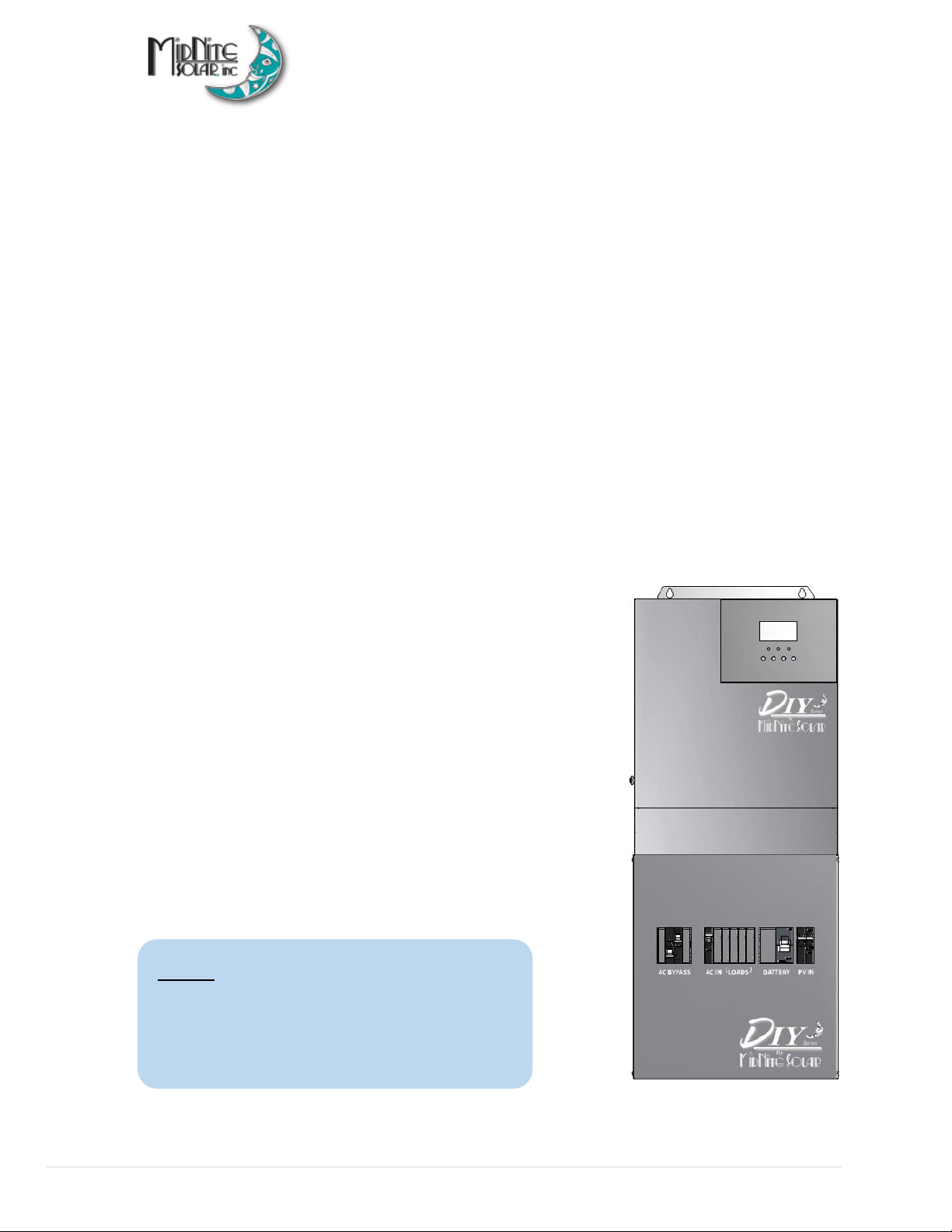
MNE125DIY-120S Manual
6| P a g e 10-545 - 1 R E V : A
manufacturer are followed to extend the life of the batteries and to prevent damage to the
batteries while charging.
•The battery bank should be installed in a clean, dry, ventilated environment that is protected
from high and low temperatures. If installed in a vehicle/boat, the batteries must be mounted
upright (if using liquid batteries) and securely fastened. The location must be fully accessible
and protected from exposure to heat producing devices, and away from any fuel tanks.
•Batteries can produce explosive gasses, so install batteries in a well-ventilated area. For
compartment or enclosure installations, always vent batteries from the highest point to the
outside. Design the battery enclosure to prevent accumulation and concentration of
hydrogen gas in pockets at the top of the compartment.
•Remove all jewelry such as rings, watches, bracelets, etc., when installing or performing
maintenance on the batteries and inverter. A battery can produce a short-circuit current high
enough to weld metal jewelry, causing severe burns.
•Use insulated tools and be very careful when working around batteries, they can produce
extremely high currents if short-circuited (e.g., dropping a metal tool across the battery
terminal), which could cause a fire or explosion.
•To prevent a spark at the battery and to reduce the chance of explosion, always connect the
cables to the batteries first. Then connect the cables to the inverter.
•Never use old or untested batteries. Check each battery’s label for age, type, and date code
to ensure all batteries are identical.
•Batteries are sensitive to changes in temperature. Install batteries in a stable environment.
•Provide at least one inch of air space between batteries to provide optimum cooling.
•Never smoke or allow a spark near batteries.
•Never charge a frozen battery.
HOW TO KILL YOUR BATTERIES
Batteries are delicate and require proper attention, especially when off-grid. Think of your
batteries and solar equipment as a small nuclear power plant, hydro dam, or natural gas-fired
power plant. Just like any of those, your system needs DAILY attention to ensure it is performing
correctly and safely. We recommend the use of an independent battery monitor/alarm if you
have an expensive battery bank. Below is a list of some of the most common ways we have seen
people kill their battery bank.
•Using more than three parallel strings and not using common bus bars. With lead-acid
batteries, when you use more than three strings, it is very hard to properly charge the
middle strings. The only safe way to do this is to wire each string with equal length cables to
a common bus bar. Connect inverter cables to the farthest points on the busbars.