MidNite Solar MNE-240 Series User manual

MNE-240 Series E-panel
Owner’s Manual

Important Information
Disclaimer of Liability
MidNite products are not intended for use in connection with Life Support Systems. MidNite Solar
makes no warranty or representation in connection with their products for such uses.
Since the use of this manual and the conditions or methods of installation, operation, use of the
E-Panel are beyond the control of MidNite Solar, this company does not assume responsibility and
expressly disclaims liability for loss, damage or expense, whether direct, indirect, consequential
or incidental, arising out of or anyway connected with such installation, operation, or use.
Important Safety Instructions
This manual contains important safety instructions that must be followed during the installation
and operation of this product.
General Precautions
• Before installing and using this product read all instructions and safety information contained
in this manual and attached to the E-Panel.
• All electrical work must be performed in accordance with local, state and federal electrical
codes.
• This product is designed for indoor/compartment installation. It must not be exposed to rain,
snow, moisture or liquids of any type.
• Use insulated tools to reduce the chance of electrical shock or accidental short circuits.
• Remove all jewelry such as rings, watches, bracelets, etc., when installing or performing
maintenance.
• Always disconnect the batteries or energy source prior to installing or performing maintenance
on the inverter. Live power may be present at more than one point since an inverter utilizes
both batteries and AC.
Battery Safety
• Wear eye protection such as safety glasses when working with batteries.
• For battery installation and maintenance read the instructions provided with the batteries
prior to installing or use.
• Never work alone; always have someone near you when working around batteries.
• Use proper lifting techniques when working with batteries.
• Never use old or untested batteries. Check each battery's label for age, type and date code to
ensure all batteries are identical.
• Batteries are sensitive to changes in temperature. Always install batteries in a stable
environment.
• Install Flooded (Liquid Lead Acid) batteries in a well ventilated area. Theses type of batteries
can produce explosive gasses. For compartment or enclosure installations, always vent batteries
to the outside.
• Provide at least one inch of air space between batteries to provide optimum cooling.
• To prevent a spark at the battery and reduce the chance of explosion, always connect the
cables to the batteries first. Then connect the cables to the inverter.
• Always verify proper polarity and voltage before connecting the batteries to the inverter.
• To reduce the chance of fire or explosion, do not short-circuit the batteries.
• In the even of accidental exposure to battery acid, wash thoroughly with soap and water. In
the event of exposure to the eyes, flood them for at least 15 minutes with running water and seek
immediate medical attention.

© 2007 MidNite Solar Page 1
MNE-240 Series E-Panel Owner’s Manual
1.0 Introduction
The MNE-240 Series E-Panel enclosure from MidNite Solar provides the basic DC and AC over-
current protection and disconnects required for a NEC compliant renewable energy system. It is
specifically designed to accommodate inverters that provide 120/240VAC in a single unit. The
MNE-240 Series E-Panel can expand to grow as your needs arise and includes the following:
• Powder-coated steel chassis with knockouts to accommodate various install needs.
• Inverter mounts on a unique hinged door to keep a small system foot-print
• E-Panel mounting brackets are included to aid in one person installations
• Inverter battery breaker, inverters cables and snap in grommets included
• 500 amp/50 mV shunt included for battery monitoring systems
• Heavy duty 150 amp bus-bars for AC HOT, NEUTRAL, GROUND, BATT +/- and PV + included
• Dual 50 amp AC input disconnects for generator or utility (prewired)
• Dual 50 amp inverter AC Bypass Switch (prewired)
• Bracket included for mounting optional charge controller (Classic or MX60)
• Inverter, remote control and charge controller mounting hardware included
• One rectangular cut-out for mounting a North American GFCI style AC outlet
• Cut-outs for mounting up to six additional 13mm wide din-rail mount AC and DC breakers (for
circuits such as PV, wind, hydro or AC distribution)
• Conforms to UL508A 1st Edition and CSA C22.2 #14-M95 (Industrial Control Panel)
2.0 Features
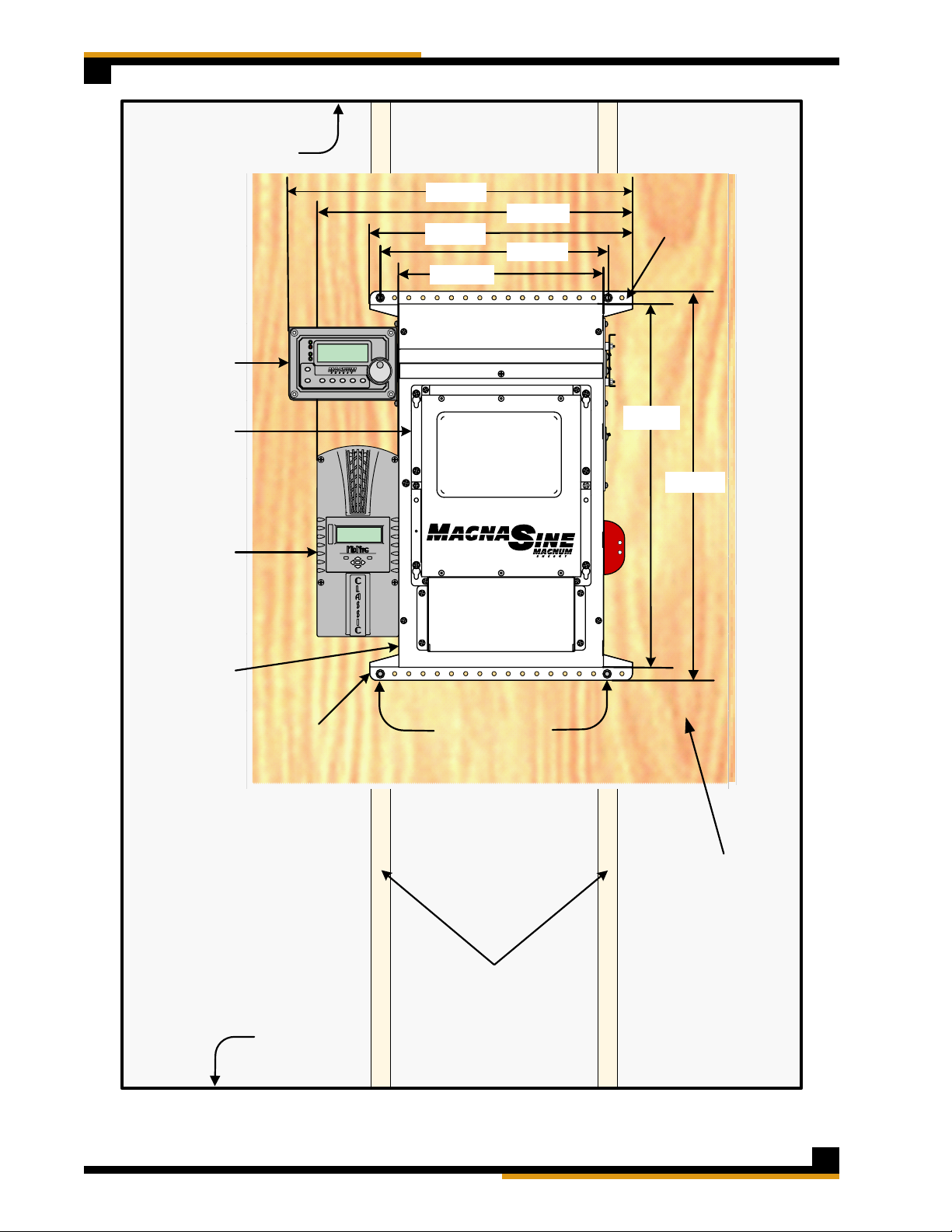
Refer to Figure 1 for the following information.
The MNE-240 Series E-Panel incorporates all the AC and DC wiring bus-bars and disconnects
required to connect the Magnum MS-AE Series inverter/charger system.
It also provides additional room to install additional equipment, such as the MidNite Classic Charge
controller (with accompanying solar array breakers/disconnects and battery temp sensors), the
Magnum Battery Monitor, a PV Ground Fault device, and AC branch breakers (that can be used
in lieu of an AC sub-panel to power the inverter’s AC loads). These additional breakers are
installed on a supplied Din-rail mounting bracket that has space for up to six 13mm sized AC or
DC breakers.
The E-Panel includes a DC Breaker used to disconnect the battery bank from the inverter as
required by the National Electric Code (NEC). This breaker is also used as an overcurrent device
to protect against extremely high currents that a battery is capable of producing if any short
circuits occur. A variety of DC Breaker options are available from MidNite Solar.
Next to the DC Breaker is a 500 amp/50 mV shunt with a DC negative bus-bar attached. The
shunt is provided so that a Battery Monitor, which is used to determine the battery bank’s state
of charge, may be easily connected without any rewiring. The DC negative bus-bar provides a DC
negative connection point for any DC loads or PV Panels in the installation.
Located on the right side of the E-Panel system is an AC input disconnect and an inverter bypass
switch. The AC disconnect is used to remove the incoming AC power to the inverter input. The
inverter bypass switch is provided to easily route the incoming AC power around the inverter and
directly to the AC loads in the system - without rewiring or losing power to the AC loads in the
system - in case the inverter needs to be removed.

© 2007 MidNite SolarPage 2
MNE-240 Series E-Panel Owner’s Manual
FRONT SIDE
30
3030
ME-RC
Remote
Control
MS-AE
Series
Inverter/
Charger
DC
Disconn
ect
In v e r tin g
DC 50.4 5ASELECT
TECHAGSMETER SETUPSHOREINVERT ER
CHARGER
INV
CHG
FAULT
PW R
ON/OFF
ON/ OFF
INVE RTER
BYPASS
ON
OFF
ON
OFF
Cutouts for GFCI AC Outlet
(not supplied)
Cutouts for up to six 13mm
Din Rail Circuit Breakers
(breakers not supplied )
Inverter Bypass Switch
LEFT
SIDE RIGHT
SIDE
Mounting Bracket for
Charge Conroller Battery Shut Off
(for inverter)
AC Input Disconnect
ME-RC Remote
Mounting Bracket
(Optional Remote available)
Lower Mounting Bracket
Upper Shield
DC Cover
Charge
Controller
Right Hinge Door
(left hinge door is available)
Upper Mounting Bracket
500A/50mV
Shunt
AC Input/Output
Bus-bars
Ground
Bus-bar
Positive and Negative Inverter Cables
Inverter AC input/Output Wires
PV Positive (+) Bus-bar
Battery
Positive (+)
Bus-bar
Battery
Negative (-)
Bus-bar
ME-BMK
Battery
Monitor
Many Knockouts with
various sizes on every side
Door Grommet (3.5")
Figure 1, MNE-240 Series E-Panel Features

© 2007 MidNite Solar Page 3
MNE-240 Series E-Panel Owner’s Manual
3.0 Installation
Before installing, read the entire installation section to determine how you are going to install
your E-Panel. The more thorough you plan in the beginning, the better your overall system needs
will be met.
A basic system diagram for the MNE-240 Series E-Panel is shown in Figure 2, MNE-240 Series
E-Panel System Wiring Diagram. This diagram should be reviewed to assist you in planning and
designing your installation.
Info: Installations should be performed by qualified personnel, such as a licensed or
certified electrician. It is the installer’s responsibility to determine which safety codes
apply and to ensure that all applicable installation requirements are followed.
Info: It is easier to install and wire any additional accessories (i.e. breakers for charge
control, the inverter, etc.) while the E-Panel is still lying horizontal on a table. Do as much
as possible before mounting the E-Panel on the wall.
3.1 Door Configuration
The standard E-Panel ships with breakers on the right side and with a right hand hinge. The
door will open to the right over the breakers. If for some reason you need the breakers on the
right, but the door to open to the left, then you can purchase the left hand door (part number
MNEleftdoorSTM-240).
Info: The circuit-breakers can be moved from the right side and reassembled on the left
side of the chassis. Even though this is possible, it is not advised. Moving the breakers is
very time consuming and the bypass switch will need to be re-positioned and rewired. It
is much more efficient to so spend the time before the installation to pre-determine and
order the correct side (left hinge or right hinge door).
3.2 Knockout Preparation
Info: See Figure 3 for the location and dimensions for the knock-outs on the MNE-240
Series E-Panel.
Think about all the different wiring required and remove the appropriate knockouts before
mounting the E-Panel. Knockouts for breakers and outlets are best accomplished using a straight
bladed screw driver and hammer. A hacksaw blade is another way to cut them out.
Determine the knockout uses for:
wiring from the E-Panel to an AC sub-panel
wire runs from utility and/or a generator to the E-Panel
battery cable wiring from the battery bank to the E-Panel
additional wiring from any external DC source (PV, Wind or Hydro) to the E-Panel
small signal wiring (battery sensors, battery monitoring, auto gen starting)
attaching lightning arrestors
charge control wiring
•
•
•
•
•
•
•

© 2007 MidNite SolarPage 4
MNE-240 Series E-Panel Owner’s Manual
Figure 2, MNE-240 Series E-Panel System Wiring Diagram
Inverter
AC Input
Disconnect
(30A)
Bypass
Switch
(50A)
Utility or Generator
120/240VAC Output
ONON
OFF
ONON
OFF
ON
OFF
ON
OFF
50A50A
ON
OFF
ON
OFF
50A50A
INVERTER
BYPASS
AC Ground
MAGNUM ENERGY
MS-AE Series
Inverter/Charger
AC WIRING DC WIRING
12V
12V 12V
12V
DC-GFP
PV + Input
PV Output
Battery Bank
(48VDC)
DC
Shunt
Main Battery
Shutoff
DC +
Buss
AC Hot In 1
AC Hot In 2
AC Neutral
AC Hot Out 1
ACHot Out 2
Battery
Temperature
Sensor
ON
OFF
63A
MIDNIGHT SOLAR
Classic Controller PV Panels
BPVPVB
PVPV
ON
OFF
ON
OFF
ON
OFF
ON
OFF
ON
OFF
ON
OFF
ON
OFF
ON
OFF
ON
OFF
ON
OFF
ON
OFF
ON
OFF
ON
OFF
ON
OFF
ON
OFF
ON
OFF
DC
Ground
ON
OFF
ON
OFF
Remote Control
DC -
Buss
From
E-Panel
(AC In)
to
Inverter
(AC In) From Inverter
(AC Out) to
E-Panel (AC Out)
ON
OFF
ON
OFF
30A 30A
120VAC
Outlet 120VAC
Oulet
240VAC
Outlet
240VAC
Output
120VAC
Output
120VAC
Output
PV +
Buss
ON
OFF
63A
ON
OFF
ON
OFF
63A 0.5A
ON
OFF
15A
ON
OFF
15A
SELECT
TECH
AG S M ETER SET UPSHO REINVERTER
CHARG ER
INV
CHG
FA U LT
PWR
ON/OFF
ON/OFF
OptionalBreakers/Disconnects
(6 spaces max@ 13mm)

© 2007 MidNite Solar Page 5
MNE-240 Series E-Panel Owner’s Manual
3.3 Knockout sizes and Dimensions
The dimensioned chassis drawing in figure 3 shows the location of the conduit knockouts, mounting
holes and mounting brackets.
Knockouts on the top surface are directly in line with ones on the bottom surface for stacking
units vertically.
•
TOP VIEW
RIGHT SIDE VIEW
UPPER CONDUIT
KNOCKOUTS ARE
MIRROR IMAGE OF
BOTTOM KNOCKOUTS
1.13" (3/4 CONDUIT)
1.38" (1" CONDUIT)
4.17"
0.87" (1/2” CONDUIT)
2.47" (2" CONDUIT)
26.45"
BOTTOM VIEW
1.75" 1 1/4” CONDUIT)
0.87" (1/2” CONDUIT)
2.47" (2" CONDUIT)
1.13" (3/4 CONDUIT)
1.38" (1" CONDUIT)
1.13"
(3/4 CONDUIT)
0.50"
LEFT SIDE VIEW
1.13" (3/4 CONDUIT)
1.38" (1" CONDUIT)
4.67" 12.90"
0.87" (1/2” CONDUIT)
2.47" (2" CONDUIT)
INSIDE 0.87" (1/2” CONDUIT)
INSIDE 2.47" (2" CONDUIT)
INSIDE 1.13" (3/4 CONDUIT)
INSIDE 1.38" (1" CONDUIT)
0.75"
1.00"
22.37"
17.00"
18.50"
14.41"
24.91"
25.55"
Figure 3, MNE-240 Series E-Panel Dimensions and Knockout Sizes

© 2007 MidNite SolarPage 6
MNE-240 Series E-Panel Owner’s Manual
Charge Controller Bracket
If installing a Charge Controller, secure the charge control bracket to the E-Panel with two #10 x
3/8” sheet metal screws supplied.
Inverter Remote Bracket
If installing the inverter remote control, secure the remote bracket to the upper left hand side
of the E-Panel with two #10 x 3/8” sheet metal screws supplied. When installing the bracket on
the right side, use two sheet metal screws and one machine screw. The remote bracket hides the
space of the AC outlet cut out, but the outlet still can be used with the bracket installed.
3.4 Installing Optional Hardware
Additional Breakers
Additional AC circuit breakers can be installed per the manufacturer’s instructions on the open DIN
Rail in the E-Panel. This DIN Rail has locations available for six additional 13mm wide AC and DC
circuit breakers. These additional circuit breakers can be used for such things as: solar, wind or
hydro charge controllers, DC ground fault protector, AC and/or DC distribution center and more.
Info: MidNite offers 150VDC breakers in 1, 6, 7, 8, 10, 12, 15, 20, 30, 50 and 63 amps.
AC breakers are available in 10, 15 and 20 amp sizes that carry the UL489 and UL489A
branch circuit rating. MidNite also offers 30, 50 and 60 amp sizes that carry the UL1077
listing for supplementary protection but are not branch circuit rated; these breakers are
rated for continuous duty and are usually used as AC disconnects.
To install additional breakers, remove the side breaker cover with the circuit-breaker cut-outs;
see figure 4. Each 13mm wide breaker requires removal of two cut-outs and the 17.5mm wide
breakers require removal of three cut-outs.
Caution: Torque the breaker terminals to 20 in. lbs. using a 1/4” wide flat-blade screwdriver
(do not use a 3/16” wide or Phillips screwdriver, they can damage the screw terminals
easily). It is highly recommended to recheck all terminations after an hour and also conduct
a pull test. You may be surprised that what you thought was a tight connection actually
pulls out with little effort. Copper is a relatively soft metal and will continue to move under
inadequate clamping pressure; a 20 inch pound of torque takes a lot of strength!
When installing DC and AC breakers together on the same din rail. Some local inspectors will
require physical separation between the AC and DC breakers. There are UL listed plastic 2” x 6”
insulators supplied with this E-Panel to fulfill this separation requirements; see figure 5.
Info: UL and the NEC allow mixing AC and DC wiring in this installation because the wire
insulation is rated for the highest voltage encountered in the enclosure. Both AC and DC
circuits are considered part of the same Renewable Energy circuit for this installation.
2 x 6" insulators
(placed between the
din-rail mounted DC
and AC breakers)
Figure 4, Removing and replacing
the breaker cover Figure 5, Insulators between AC and DC
breakers

© 2007 MidNite Solar Page 7
MNE-240 Series E-Panel Owner’s Manual
3.5 Locating and Mounting the E-Panel
Review Figure 6, MNE-240 Series E-Panel Mounted to determine the mounting space requirements
for the E-Panel with the inverter/charger and any other optional equipment that may be mounted.
Info: Do as much of the additional wiring as possible before hanging the E-Panel on the
wall.
Install the E-Panel in a location that meets the following requirements:
• The E-Panel must be mounted vertically on a flat surface (such as a wall).
• Do not mount the E-Panel near any flammable or combustible fluid or components (i.e. paper,
cloth, plastic, etc.) that may be ignited by heat, sparks or flames - they must be at a minimum
distance of 2 feet away from the E-Panel/inverter.
• Τhis E Panel system will weigh approximately 100 pounds. The mounting surface and hardware
must be capable of supporting at least twice the weight of the E-Panel/inverter combination.
• The area must be free from any risk of condensation, water or any other liquid that can enter
or fall on the inverter.
• Locate the E-Panel and inverter system as close to the batteries as possible. Long DC wires
tend to loose efficiency and reduce the overall performance of an inverter. However, the unit
should not be mounted where it will be exposed to gases produced by the batteries. These
gases are corrosive and will damage the inverter; also if these gases are not ventilated and if
allowed to collect, they could ignite and cause an explosion.
• Ensure the E-Panel is accessible after it is mounted. Select a wall that has suitable clearance
to open the door with the inverter attached. It must also have adequate clearance to operate
the breakers and outlets that protrude out the sides.
E-Panel Mounting Procedure
Info: Prior to mounting the E-Panel to the wall, ensure the bottom mounting bracket has
been installed and the door has been removed.
1. Use a level and hold the top mounting bracket on the wall in a horizontal position and mark on
the wall where you want the mounting screw holes.
2. If required, drill holes using a #10 (0.193” diameter) drill bit. Drill appropriately sized holes for
anchors when installing on non-wood surfaces.
3. Secure the top mounting bracket to the wall using the three ¼ X 1½ hex-head lag bolts. If
mounting to other than a wood wall or surface, use appropriate screws and anchors as required.
4. Lift the E-Panel and place the keyhole slots (located in the upper back of the E-Panel) directly
over the mounting screws on the mounting bracket and lower into place.
5. Tighten the top mounting screws to secure the E-Panel to the mounting bracket.
6. Secure the bottom mounting bracket to the wall.

© 2007 MidNite SolarPage 8
MNE-240 Series E-Panel Owner’s Manual
Wall studs
16 inches on center
Floor
Ceiling
Mounting
Bolts (x4)
22.37"
14.41"
SELECT
TECHAG S M ETER SETUPSHO REINVERTER
CHARG ER
INV
CHG
FA U LT
PWR
ON/OFF
ON/ OFF
22.23"
16.00"
18.50"
24.91"
Plywood
26.45"
Remote
Control
Magnum
Inverter/
Charger
MidNite
Solar
Classic
Controller
MNE-240
Series
E-Panel
Bottom
Mounting
Bracket
Top Mounting
Bracket
Figure 6, MNE-240 Series E-Panel Mounted

© 2007 MidNite Solar Page 9
MNE-240 Series E-Panel Owner’s Manual
3.6 Mounting the Inverter
Before mounting the inverter to the chassis, complete all wiring that will be coming to and going
from the E-Panel.
Figure 7 shows additional wiring for adding lightning arrestors (top of enclosure), wiring circuit
breakers for charge controllers (right side in the middle), tying down the remote control com-
munication cable (left side), and connecting the GROUND bus-bar to the NEUTRAL bus-bar when
this E-Panel is used as the main electrical panel.
As shown in figure 8, secure the inverter to the E-Panel door using six 6 mm x 20 mm taptite (thread
forming) pan head Phillips screws. These 6 mm screws require a #3 Phillips screwdriver. Use one
of these 6 mm screws to pre-tap threads into the steel doors extruded funnel holes. Ensure a ¼”
star washer is used with one of the 6 mm screws to bite through the powder coating.
Once the inverter is secured to the door, lift it into the E-Panel hinge openings as shown in figures
9 and 10.
One of the best features of the E-Panel is that one person can do all the lifting.
Figure 7, Additional Wiring with E-Panel
Mounted Figure 8, Securing the Inverter to the
E-Panel Door
Figure 9, Lifting the door into the E-Panel
hinge openings Figure 10, Ensuring door is in all three
hinge openings and moves freely

© 2007 MidNite SolarPage 10
MNE-240 Series E-Panel Owner’s Manual
3.7 Wiring the E-Panel and Inverter
Review the following information prior to wiring the E-Panel it is imperative that the following steps
be taken to help reduce the risk of electric shock to you and damage to the E-Panel/inverter.
1. Disconnect the main AC panel that will feed the E-Panel (if using utility power) by switching
off the main circuit breaker. Lock out the AC breaker box to ensure no one will accidentally turn
the power on during the installation process. If the AC panel does not have provision for locking
the breaker box, place a sign on the box and tape the door closed to warn others from opening
or turning on the AC panel.
2. Place the main DC shutoff breaker (DC disconnect) in the OFF position.
3. If additional breakers are installed, place them in the OFF position.
4. Turn the inverter bypass switch to the “BYPASS” position (see the label on the bypass switch).
Pre-Wiring Requirements
All wiring and installations methods should conform to applicable electrical and building codes.
Always check for existing electrical, plumbing or other areas of potential damage prior to
making cuts in structural surfaces or walls.
Make sure all wires have a smooth bend radius and do not become kinked.
Both AC and DC overcurrent protection must be provided in this installation.
Use only copper wires with a minimum temperature rating of 75° C (176° F) to connect to the
wiring terminals.
All wiring within the E-Panel enclosure, except low voltage control wiring, shall be rated at least
250V or a combination of 250V (e.g., 125V cable enclosed in 125V insulation/heat shrink).
All wiring to the battery terminals should be checked periodically (once a month) for proper
tightness.
•
•
•
•
•
•
•
Install the Door Grommets
All wires that need to pass through the door of the E-Panel must
be routed through the provided serrated snap-in grommets. These
grommets help minimize wire insulation damage such as chafing,
which can be caused by constant rubbing when opening and
closing the door. A 3.5” plastic grommet is supplied and should
be snapped into the larger hole in the door as shown in figure 11.
The smaller 1” hole can be used for small signal wires (e.g. remote
communications wire, battery temperature sensor cable, etc.), but
no grommet is provided. It is important to route the wires so the
door closes freely without undue force.
Grounding
The E-Panel should be connected to a grounded, permanent wiring system.
DC Grounding - The negative battery conductor should be bonded to the grounding system at
only one point in the system. The size for the conductor is usually determined by the size of the
DC overcurrent protection (DC disconnect) per the NEC/CEC.
If the MNDC-GFP ground fault protector is installed, DO NOT connect battery negative to ground
- this connection is accomplished by the MNDC-GFP. Any additional DC grounding will make the
MNDC-GFP inoperative.
AC Grounding - The AC neutral and ground should only be bonded at the main service panel for
the AC system.
Figure 11, Installing 3.5”
Grommet in the Door

© 2007 MidNite Solar Page 11
MNE-240 Series E-Panel Owner’s Manual
Battery Bank
Positive (+)
connection Battery Negative
(–) Bus
(for PV Input/
DC Loads)
DC CONNECTIONS
AC CONNECTIONS
Battery Cable
To Inverter
Negative (-)
connection
Battery Cable
to Inverter
Positive (+)
connection
Battery Bank
Negative (-) connection
AC HOT
OUT 1
(to sub-panel
or circuit
breakers)
DC
GROUND
connection
AC HOT IN 1
(from Utility/
Generator)
AC
NEUTRAL
connection
Battery
Positive (+)
Bus
(for DC Loads)
AC
GROUND
connection
AC HOT
IN 2
(from Utility/
Generator)
Battery
Positive (+)
Bus
(for PV Input)
AC HOT
OUT 2
(to sub-panel
or circuit
breakers)
Battery Bank
Positive (+)
connection
Battery Negative
(–)Bus
(for PV Input/
DC Loads)
DC CONNECTIONS
AC CONNECTIONS
Battery Cable
To Inverter
Negative (-)
connection
Battery Cable
to Inverter
Positive (+)
connection
Battery Bank
Negative (-) connection
AC HOT
OUT 1
(to sub-panel
or circuit
breakers)
DC
GROUND
connection
AC HOT IN 1
(from Utility/
Generator)
AC
NEUTRAL
connection
Battery
Positive (+)
Bus
(for DC Loads)
AC
GROUND
connection
AC HOT
IN 2
(from Utility/
Generator)
Battery
Positive (+)
Bus
(for PV Input)
AC HOT
OUT 2
(to sub-panel
or circuit
breakers)
Figure 12, E-Panel Wiring Connections
AC Wiring Connections
The AC Bus-Bars (for neutral and hot connections) have dual sizes. The smaller nine holes accept
#6 to 14 AWG wire and the larger two holes accept #1/0 to 14 AWG. Torque small screws to 30
in-lbs (3.4 NM) and the large screws to 45 in-lbs (5.1 NM).
DC Wiring Connections
The DC bus-bars (for battery positive/negative and PV) have dual sizes. The smaller nine holes
accept #6 to 14 AWG wire and the larger two holes accept #1/0 to 14 AWG. Torque small screws
to 30 in-lbs (3.4 NM) and large screws to 45 in-lbs (5.1 NM).
The DC shunt uses 3/8” bolts and requires cables having ring terminal lugs with a 3/8” hole.
Torque these bolts between 10 to 12 foot-pounds.
The 175A and 250A DC Disconnect (Main Battery Shut-Off) uses a 3/8-16 stud and requires
cables having ring terminals with a 3/8” hole. The 125A DC Disconnect has 1/4-20 studs and
requires cables with a 1/4” hole. Torque the 175 A and 250 A breakers to 220 in-lbs (24.9 NM)
and torque 125 amp breakers to 30 in-lbs (3.4 NM).
Ground Connections
The ground bar has nine holes and accepts #6 to 14 AWG wires. Torque small ground screws to
20 in-lbs (2.3 NM) and the large ground screws to 45 in-lbs (5.1 NM).
E-Panel with Left Hand Door E-Panel with Right Hand Door

© 2007 MidNite SolarPage 12
MNE-240 Series E-Panel Owner’s Manual
3.9 DC Cable Wiring
It is important to use the correct DC cable and corresponding circuit breaker to achieve maximum
efficiency from the system and reduce fire hazards associated with overheating. See the MS-AE
Series Owner’s Manual to determine the minimum DC cable size needed based on your inverter
model and the total cable distance.
Pre-DC Wiring Checklist
DC wires and cables should be tied together with wire ties or electrical tape approximately every
6 inches. This helps improve the surge capability and reduces the effects of inductance, which
improves the inverter waveform and reduces the wear of the inverter’s filter capacitors.
The DC cables/wires must be color coded with colored tape or heat shrink tubing: RED for positive
(+); WHITE for negative (-); and GREEN for DC ground.
It is important to route the cables so the doors close freely without undue force.
The inverter uses 5/16” bolts and requires cables having ring terminal lugs with a 5/16 hole.
Torque these bolts between 10 to 12 foot-pounds.
To ensure the maximum performance from the inverter, all connections from the battery bank
to the inverter should be minimized. Any additional connection may contribute to additional
voltage drops and may loosen during use.
The DC cables must be a fine strand super flexible, such as Cobra cable (or equivalent) and
be approved for residential wiring per the NEC (THW for example).
Caution: The inverter is NOT polarity protected; the battery’s negative and positive terminals
MUST be correctly connected to the inverter’s negative and positive terminals before turning
ON the DC battery breaker or damage will occur. The inverter’s warranty doesn’t cover
repair to the inverter from this damage.
Caution: The battery bank voltage MUST match the inverter’s required DC voltage (i.e.
48vdc battery for a 48vdc inverter) or the inverter may be damaged.
Info: After making the battery connections, cover the outside of the connection with
petroleum jelly or another form of battery terminal anticorrosive grease. Do not put anti-
corrosion grease between the terminal and the battery cable.
Connecting the DC cables
Refer to figure 13 for connecting the cables in the following steps:
Info: Figure 13 shows the battery cables coming from below, but the E-Panel has knockouts
that allows the cables to come from the sides or back.
Connecting the Inverter DC Cables
1. Route the pre-wired positive (+) battery cable from the DC disconnect in the E-Panel through the
grommet/door and connect to the positive battery terminal on the inverter.
2. Route the pre-wired negative (-) battery cable from the DC shunt in the E-Panel through the
grommet/door and connect to the negative battery terminal on the inverter.
Connecting the Battery DC Cables
1. Route a DC cable from the negative (-) battery terminal of the battery bank through the
conduit/E-Panel knock-outs and connect to the open terminal on the DC shunt.
2. Route a DC cable from the positive (+) battery terminal of the battery bank through conduit
and connect to the bottom (source) side of the DC disconnect.
Connecting the Battery Temperature Sensor (BTS)
1. Connect the BTS ring terminal end to the negative terminal on the battery bank. Route its cable
from the battery bank through either the 3.5” or 1” hole in the E-Panel door and connect to the
inverter’s RJ11 BTS PORT (yellow label).
•
•
•
•
•
•

© 2007 MidNite Solar Page 13
MNE-240 Series E-Panel Owner’s Manual
DC Ground
(from battery to E-Panel
Battery Bank(48VDC)
The battery bank voltage MUST match the DC voltage
required by the inverter (i.e. 48-volt battery bank for a 48-
volt inverter) or the inverter may be damaged.
12V
12V 12V
12V
Inverting
DC 50.4 5A SELECT
TECHAG S METE
RSETU
P
SHO R
E
INVERTE
R
CHARG E
R
INV
CHG
FA U L
T
PWR
ON/ OFF
ON/
OFF
303030
DC Positive
(from battery to disconnect)
Battery Temp Sensor
(from battery to inverter)
Wire Grommet
(snapped into door )
DC Negative
(from battery to shunt)
Remote Cable
(from remote
to inverter)
ME-RC
Remote
Control
MidNite MNE-240 Series E-Panel
MS-AE
Series
Inverter/
Charger
DC Positive
(from disconnect
to inverter)
DC Negative
(from shunt to inverter)
Battery Temp Sensor
(from battery to
inverter)
DC Negative
(from shunt to inverter)
Remote Cable
(from remote
to inverter)
DC Positive
(from disconnect to
inverter)
GROUND
DC Shunt
DC
Disconnect
Figure 13, E-Panel DC and Accessory Wiring

© 2007 MidNite SolarPage 14
MNE-240 Series E-Panel Owner’s Manual
3.10 AC Wiring
The full AC pass-thru capacity of the MS-AE Series inverter/charger is 30 amps for both AC legs
(AC HOT 1 and AC HOT 2). To obtain the full pass-thru capability of the inverter and protect the
inverter’s pass-thru relay, use a maximum 30 amp double-pole breaker, which corresponds to a
cable size of #8 AWG (THHN) in conduit. If you are using other wire sizes, please refer to your
local electrical code for breaker requirements.
Pre-AC Wring Checklist
AC input to the inverter requires a maximum 30 amp circuit-breaker to each of the inverter’s
AC Hot inputs. If the dual-pole AC input disconnect in the E-Panel is rated for 30 amps, it will
meet this requirement.
AC Loads powered by the inverter will need to installed into an electrical sub-panel; or optional
branch-rated breakers may be may be installed in the E-Panel and used to power these AC
loads.
Always use properly rated circuit-breakers. If using an electrical sub-panel, circuit breakers
can be moved from the main electrical panel to the sub-panel only if the breakers are also
listed to be installed in the sub-panel.
AC wiring must be no less than 10 AWG (5.3 mm2) gauge copper wire and be approved for
residential wiring per the NEC (THHN as an example).
Connecting the AC wires
Connecting E-Panel AC Input/Output Wires (refer to Figure 12 and 14 for the following steps):
1. Route two wires [AC hot 1 (black/L1) and AC hot 2 (red/L2)] from a double-pole circuit breaker
in the main panel and connect to the AC HOT IN 1 and AC HOT IN 2 bus-bars in the E-Panel
respectively.
2. Route a wire from the neutral bus-bar in the main panel and connect to the NEUTRAL bus-bar
in the E-Panel.
3. Route a wire from the ground bus-bar in the main panel and connect to the GROUND bus-bar
in the E-panel.
4. Route wires from the AC HOT OUT 1 (black/L1), AC HOT OUT 2 (red/Leg 2), NEUTRAL and
GROUND bus-bars in the E-Panel and either connect to: A) the sub-panel, or B) to each individual
circuit breaker if installed in the E-Panel.
Connecting to the Inverter AC terminals
Before connecting the wires to the inverter’s AC terminal block: 1. Ensure the wires are routed
through the 3.5” grommet in the door; and 2. Establish the correct length of wire by opening and
closing the door, then cut back the wires as required.
Info: Remove the AC access cover to expose the AC terminal block in the MS-AE Series
Inverter as described in owner’s manual.
For the following steps, refer to figure 4-5 to locate the #8 AWG wires in the E-Panel:
1. Connect the black wire labeled AC HOT OUT to the inverter’s AC HOT OUT 1 terminal.
2. Connect the red wire labeled AC HOT OUT to the inverter’s AC HOT OUT 2 terminal.
3. Connect the white wire from the NEUTRAL bus-bar in the E-Panel to either one of the inverter’s
AC NEUTRAL terminals.
4. Connect the black wire labeled AC HOT IN to the inverter’s AC HOT IN 1 terminal.
5. Connect the red wire labeled AC HOT IN to the inverter’s AC HOT IN 2 terminal.
Info: A ground wire from the E-Panel to the inverter AC ground terminal is not required,
because the inverter is sufficiently grounded through the E-Panel to the permanent ground
system. A ground wire may be connected from the GROUND bus-bar in the E-Panel to the
inverter’s AC GROUND for additional redundancy.
•
•
•
•

© 2007 MidNite Solar Page 15
MNE-240 Series E-Panel Owner’s Manual
AC
Output
Wiring
Main Panel
(Utility/Generator Input )
ON
OFF
ON
OFF
ON
OFF
ON
OFF
ON
OFF
ON
OFF
ON
OFF
ON
OFF
ON
OFF
ON
OFF
ON
OFF
ON
OFF
ON
OFF
AC Input Wiring-
120/240VAC from Main
Panel to AC HOT IN and
NEUTRAL Bus-bars
AC Output Wiring -
a) Wire to an electrical
sub-panel,
or
b) Use optional circuit
breakers installed
in the E-Panel.
b) AC Output Wiring (using optional circuit-breakers)
AC Ground
AC Neutral
AC Hot Out 1
AC Hot Out 2
240VAC Output
120VAC Output
120VAC Output
120
VAC
120
VAC
240
VAC
ON
OFF
15A
ON
OFF
ON
OFF
30A 30A
ON
OFF
15A
a) AC Output Wiring (using sub-panel)
AC Ground
AC Neutral
AC Hot Out 1
AC Hot Out 2
120
VAC
120
VAC
240
VAC
ON
OFF
ON
OFF
ON
OFF
ON
OFF
Figure 14, E-Panel AC Input and Output Wiring

© 2007 MidNite SolarPage 16
MNE-240 Series E-Panel Owner’s Manual
30
3030
Inverting
DC 50.4 5A SELECT
TECHAG S M ETER SETUPSHO REI NVERTER
CHARG ER
INV
CHG
FAULT
PWR
ON/OFF
ON/OFF
3.5" Wire Grommet
(snapped into door )
ME-RC
Remote
Control
MidNite MNE-240 Series E-Panel
MS-AE
Series
Inverter/
Charger
AC Inverter wires
(pre-wired in the E-Panel)
GROUND
DC
Disconnect
AC HOT IN(black)
AC HOT IN (red)
AC HOT OUT (black)
AC NEUTRAL(white)
AC HOT OUT (red)
ACHOTIN(black)
AC HOT IN (red)
AC HO T O UT ( blac k)
AC NEUTRAL (white )
ACHOT OUT(red)
Inverter’s AC HOT OUT 2
Inverter’s AC NEUTRAL
(either terminal )
Inverter’s AC HOT OUT 1
Inverter’s AC HOT IN 2
Inverter’s AC HOT IN 1
Figure 15, MS-AE Series Inverter AC Wiring

© 2007 MidNite Solar Page 17
MNE-240 Series E-Panel Owner’s Manual
3.11 Final Installation Tidbits:
Wiring the Inverter Remote Control
Refer to figure 13 for the following steps:
1. Connect one of the RJ11 connector ends of the remote communication cable to the back of the
remote; refer to the ME-RC owner’s Manual for specific information.
2. Route the other RJ11 connector end through the E-Panel and E-Panel door and connect to the
inverter’s RJ11 REMOTE PORT (blue label).
Additional Accessory Wiring
Before attaching the DC cover to the inverter end, if you have any of the following inverter
accessories, then you will also need to route their connecting cables through the E-Panel (and
pass through the small snap-in grommet in the door) to the RJ11 Ports on the inverter:
• Automatic Generator Start Controller (ME-AGS) for automatic generator starting an stopping.
• Battery Monitor (ME-BMK-NS) for determining your batteries State of Charge.
• Simple ON/OFF adapters (ME-RSA, ME-RSA-M) that allow the inverter to be remotely turned
on/off.
See the appropriate accessory owner’s guide or further information about the installation and
configuration of these accessories.
Installing Inverter Shield/Covers
Refer to figure 1 to identify the following components:
Upper Shield - Attach the upper shield to the E-Panel door using three 10-32 x 3/8” machine
screws and kepnuts.
DC Cover - Attach the DC cover using four 10-32 x 7/16” taptite screws and at least one #10
internal tooth star washers.

© 2007 MidNite SolarPage 18
MNE-240 Series E-Panel Owner’s Manual
4.0 Start-up and Testing
After the DC and AC wiring has been completed, a series of voltage checks should be performed
to ensure the system wiring is correct. If any of the tests fail, recheck the AC wiring.
Before beginning, ensure all circuit breakers pertaining to the E-Panel system are OFF, this
includes:
all circuit breakers in the main panel from all AC sources (utility or generator, if any) feeding
the E-Panel.
all circuit breakers in the sub-panel (if used).
all circuit breaker within the E-Panel, this includes the AC Input disconnect, the DC Disconnect
Breaker, and any additional AC or DC breakers installed.
A. Testing the Inverter AC Output Wiring
1. Slide the Inverter Bypass switch to the “INVERTER” position and turn the battery DC disconnect
to the ON (up) position.
2. Turn ON the inverter as outlined in the MS-AE Owner’s Manual (or ME-RC Owner’s Manual if
using a remote control). The inverters should be providing 120/240 VAC to the E-Panel AC Output
Bus-Bars (ensure the inverter is not in search mode).
3. Inside the E-Panel enclosure, use an AC voltmeter and measure the inverter voltage (Refer to
figure 16 for the following voltage checks):
a. between the AC HOT OUT 1 bus-bar and the NEUTRAL bus-bar, this voltage should be 120
Vac (± 3%).
b. between the AC HOT OUT 2 bus-bar and the NEUTRAL bus-bar, this voltage should be 120
Vac (± 3%).
c. between the AC HOT OUT 1 bus-bar and the AC HOT OUT 2 bus-bar, this voltage should be
240 Vac (± 3%).
B. Testing the E-Panel AC Input/Output Wiring
1. If the Inverter AC output voltages are correct (tested above): a) turn the inverter OFF; b) slide
the Inverter Bypass switch to the “BYPASS” position; c) switch ON the circuit breakers in the AC
main panel switch (from the generator or utility) feeding the E-Panel; and switch the AC input
disconnect to ON. These tests assume that the AC input source (Utility/Generator) is 120/240VAC
and that the neutral and ground are bonded together by the incoming AC source.
2. In the E-Panel, use an AC voltmeter and measure the generator or utility voltage (Refer to
figure 16 for the following voltage checks):
a. between the AC HOT OUT 1 bus-bar and the NEUTRAL bus-bar, this voltage should be 120
Vac (± 3%).
b. between the AC HOT OUT 2 bus-bar and the NEUTRAL bus-bar, this voltage should be 120
Vac (± 3%).
c. between the AC HOT OUT 1 bus-bar and the AC HOT OUT 2 bus-bar, this voltage should be
240 Vac (± 3%).
d. between the NEUTRAL bus-bar and the GROUND bus-bar, this voltage should be <0.5 Vac.
3. If all voltages/tests are correct, a) turn the inverter ON; b) slide the Inverter Bypass switch to
the “INVERTER” position; c) switch ON the circuit breakers either in the E-Panel or in the AC sub-
panel, depending on which is used for the inverter AC loads. Verify the inverter is charging the
batteries and powering the inverter AC loads.
4. Secure all covers/panels on the E-Panel, inverter, main panel and sub-panel (if used).
The MNE-240 Series E-Panel system is now tested and ready for operation. If the inverter needs
programming or is not operating properly, refer to the MS-AE Series Owner’s Manual for setup
and troubleshooting information.
•
•
•
Other manuals for MNE-240 Series
1
This manual suits for next models
1
Table of contents
Other MidNite Solar Power Distribution Unit manuals