Brusa PDU254 Series Instruction manual

www.brusa.biz
PDU254
ASM
TECHNICAL DATA
AND START-UP
Translation of the original German operating instructions

Technical data
and start-up
PDU254
2
LEGAL NOTICE
Publisher
BRUSA Elektronik AG
Neudorf 14
CH–9466 Sennwald
T +41 8175 809–00
F +41 8175 809–99
www.brusa.biz
Date of issue
19. January 2013
Copyright
© 2012
The content of this document may not be passed on to third parties without the written authorisation
of the company BRUSA Elektronik AG - not even in extracts. All technical information, drawings and
photos used in this document are protected by copyright and any infringement constitutes a
punishable offence!
Updates
In light of the further technical development of our products, we reserve the right to make
constructional changes. Any changes will be disclosed in the relevant manuals through the
replacement of the relevant pages and/or a revision of the electronic data storage device.
Writer / Author
Holger Schmidt
REVISIONS
REVISION
DATE
NAME
CHANGE
01
30.04.2013
H. Schmidt
Chap 3.3, 3.5, 7.4, 7.4.2 small corrections
Chap 6.7.3 and 6.7.4 added
02
06.08.2013
M. Tschumper
Chap 8.1 new, 8 small corrections
03
27.01.2014
M. Tschumper
Chap 3.5 Principle of operation Interlock
04
18.02.2014
M. Tschumper
Chap 6.5.1 added signal pin in diagram
05
20.02.2014
M. Tschumper
Chap 8 grafic 7.12..14.15
06
12.02.2015
R. Roth
Chap 4.2 adjust the scope of delivery
Chap 8 adjust table with information about the screw
07
04.06.2015
F. Müller
Chap 8.1 add information about cable and terminal insert
08
28.11.2016
A. Girod
Chap 9 updated
09
26.06.2017
M. Cvorak
Chap 6.1 DEL: discharge resistor;
Chap 7.4.2; 7.4.4 DEL: reverence to active discharge

3
Technical data
and start-up
PDU254
VALIDITY
This manual is only valid for the devices listed in the following table:
PDU254-A01
PDU254-A02
The decoding of the device designation is as follows:

Technical data
and start-up
PDU254
4
TABLE OF CONTENTS
1Foreword..............................................................................................................................6
2List of abbreviations ...........................................................................................................6
3Safety and warning instructions........................................................................................7
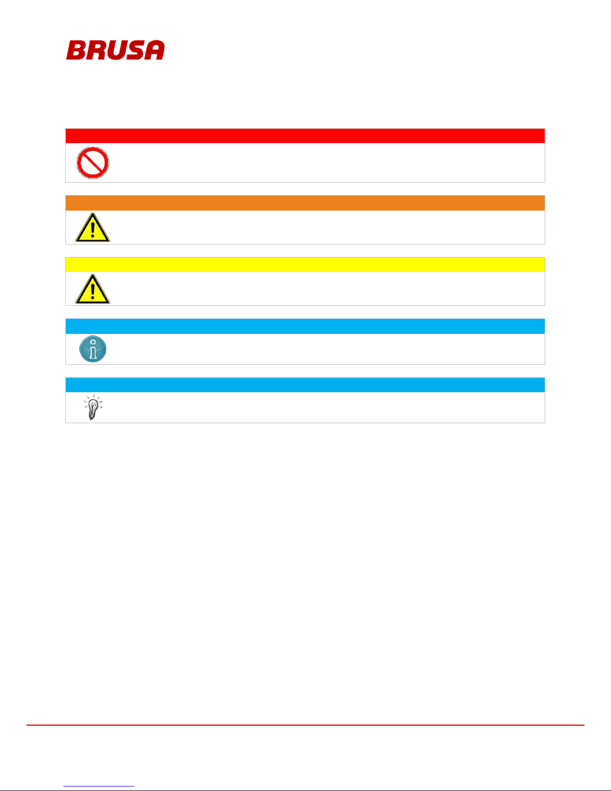
3.1 Symbols and their meaning........................................................................................................7
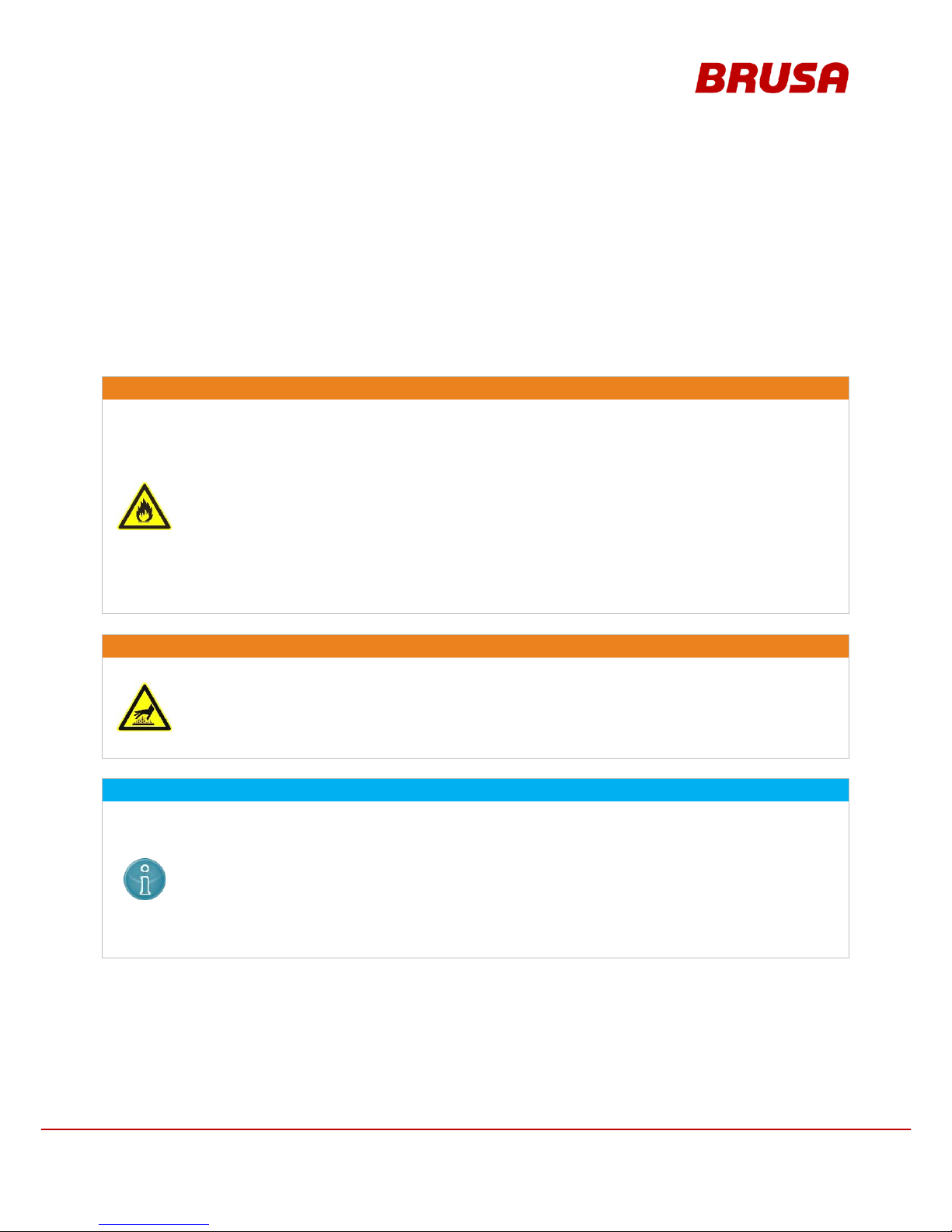
3.2 Safety instructions and danger levels.........................................................................................8
3.3 Generally applicable safety measures........................................................................................9
3.3.1 Safety instructions for handling and operation.....................................................................9
3.3.2 Safety instructions for electrical systems...........................................................................10
3.4 Safety installations ...................................................................................................................11
3.4.1 Interlock switch..................................................................................................................11
3.4.2 Shorting link ......................................................................................................................12
3.5 Safety concept for vehicle installation.......................................................................................13
3.5.1 Principle of operation Interlock ..........................................................................................13
3.6 Requirements regarding the start-up personnel........................................................................14
4General...............................................................................................................................14
4.1 Content and scope of this manual............................................................................................14
4.2 Scope of the entire documentation...........................................................................................14
4.3 Scope of delivery......................................................................................................................15
4.4 Optional delivery contents........................................................................................................17
4.5 Applicable standards................................................................................................................17
4.6 Contact information of the manufacturer...................................................................................17
5Use and limits of the product...........................................................................................18
5.1 Proper use................................................................................................................................18
5.2 Improper use............................................................................................................................18
6About this device...............................................................................................................19
6.1 Technical data..........................................................................................................................19
6.2 Technical properties.................................................................................................................20
6.3 Warnings on the PDU...............................................................................................................20
6.4 Overview of the main structural components............................................................................21
6.5 Basic function PDU254 ............................................................................................................22
6.5.1 Block diagram PDU254.....................................................................................................22

5
Technical data
and start-up
PDU254
6.6 Basic principle of vehicle installation ........................................................................................23
6.7 Dimensions and installation information ...................................................................................24
6.7.1 Fixing points......................................................................................................................24
6.7.2 Housing dimensions..........................................................................................................25
6.7.3 Interface dimensions.........................................................................................................25
6.7.4 Fully assembled view........................................................................................................26
6.8 Type plate................................................................................................................................26
7Connections.......................................................................................................................27
7.1 Input side .................................................................................................................................27
7.2 Output side...............................................................................................................................28
7.3 Earth GND................................................................................................................................29
7.4 Pin assignment of control connector (device side)....................................................................30
7.4.3 Pin 4 DO0 .........................................................................................................................32
7.4.4 Pin 5 DO1 .........................................................................................................................32
7.4.5 Pin 7 DO3, pin 16 DI0 .......................................................................................................33
7.4.6 Pin 19 IL1, pin 20 IL2 ........................................................................................................33
8Installation / initial start-up...............................................................................................34
8.1 Connecting the HV lines...........................................................................................................41
9Warranty.............................................................................................................................44
10 Instructions for disposal ...............................................................................................44
11 Index................................................................................................................................45

Technical data
and start-up
PDU254
6
1 Foreword
Dear customer!
With the BRUSA PDU254, you have obtained a very capable and versatile product. As this is a power electronics
product, specialist knowledge is required for dealing with it as well as operating it!
Read this manual –in particular the chapter Safety and warning instructions–carefully before installing the battery
or carrying out any other work on it!
2 List of abbreviations
Throughout this manual, some specific technical abbreviations are used. The following table provides an overview
of these abbreviations and their meaning:
ABBR.
MEANING
ABBR.
MEANING
AUX
Auxiliary
IL
Interlock
BSC
On-board converter
NLG
Netzladegerät (mains charger)
DMC
Digital Motor Controller (inverter)
PDU
Power Distribution Unit
EMC
ElectroMagnetic Compatibility
PTC
Resistor with Positive Temperature
Coeffizient
HF
High Frequency
RXT
Range Extender
HV
High Voltage

7
Technical data
and start-up
PDU254
3 Safety and warning instructions
In this chapter, you will find safety instructions applying to this device. These instructions refer to the assembly,
start-up and the running operation in the vehicle. Always read and observe these instructions in order to protect
people's safety and lives and to avoid damage to the device!
3.1 Symbols and their meaning
Throughout this manual, some specific technical symbols are used. The following table provides an overview of
these symbols and their meaning:
PROHIBITION SYMBOLS
SYMBOL
MEANING
SYMBOL
MEANING
General prohibition
Warning! High voltage!
Do not touch!
Do not switch!
WARNING SYMBOLS
SYMBOL
MEANING
SYMBOL
MEANING
General hazard warning
Warning! Danger caused by suspended
loads!
Warning! Explosive environment!
Warning! Danger caused by batteries!
Warning! Hot surface!
Warning! High voltage!
Warning! High pressure / fluid ejection!
Warning! Fire hazard!
MANDATORY SIGNS
SYMBOL
MEANING
SYMBOL
MEANING
Disconnect device from voltage
Disconnect device from mains
Wear protective glasses
Wear protective gloves
INFORMATION SIGNS
SYMBOL
MEANING
SYMBOL
MEANING
Important information on avoiding possible
damage to property
Important information

Technical data
and start-up
PDU254
8
3.2 Safety instructions and danger levels
DANGER
This instruction warns against serious, irreversible risks of personal injury with possibly fatal
consequences!
Avoid these risks by observing these instructions!
WARNING
This instruction warns against serious but reversible risks of injury!
Avoid these risks by observing these instructions!
CAUTION
This instruction warns against a minor risk of injury!
Avoid these risks by observing these instructions!
INSTRUCTION
This instruction warns against possible damage to property if the following instructions and work
procedures are not observed.
INFORMATION
This type of instruction discloses important information for the reader.

9
Technical data
and start-up
PDU254
3.3 Generally applicable safety measures
The following safety measures have been developed based on the knowledge of the manufacturer. They are
incomplete as they can be supplemented by local and/or country-specific safety instructions and guidelines for
accident prevention!
The system integrator and/or distributor of the device must therefore supplement the present general safety
instructions by country-specific and local guidelines.
3.3.1 Safety instructions for handling and operation
WARNING
Overheating!
Fire hazard!
The plus and minus poles must not be bypassed using a metallic object! This will lead to a short-
circuit and fast overheating of the device and the cables!
Do not carry out any unauthorised work on the PDU! This may cause the safety installations to
be disabled and could lead to fires as a consequence!
The device must by no means be subjected to rough mechanical impacts! This could destroy the
circuit boards and lead to short-circuits and fires as a consequence!
Do not store any highly flammable substances or combustible fluids in the direct surroundings of
the device! Sparks forming at the device connections can set these on fire and lead to
explosions!
WARNING
Hot surfaces!
Burn hazard!
The device produces high levels of waste heat when in operation. Carelessly touching the device
can cause burns to the skin! Therefore, the device is to be handled with care and caution at all
times! Avoid operating the device close to heat sources or in direct sunlight!
INSTRUCTION
Even though the PDU has a high IP protection class, direct contact with water (rain, splashing
water) during operation is to be avoided as far as possible!
Under no circumstances should you put a low-resistance connection between the HV contacts,
the housing contacts and the LV contacts! This will lead to malfunctions and furthermore to the
destruction of the PDU!
Before connecting the cabling, make sure that the battery cables have been properly connected!
Reverse polarity can lead to the destruction of not only the battery but of other devices as well!
Check if the used system voltage is within the admissible range before connecting the cabling!

Technical data
and start-up
PDU254
10
3.3.2 Safety instructions for electrical systems
DANGER
High voltage!
Danger to life!
Do not touch the HV wires or connections without ensuring the absence of voltage beforehand!
The PDU may only be connected by a qualified electrician!
Safety installations must not be by-passed or avoided! Any resulting malfunctions could have life
threatening consequences!
Before carrying out any work on the PDU, make sure that the coupled motor has come to a
complete standstill! Even when the HV supply is switched off, a turning motor can still produce
voltage!
INFORMATION
When working on a HV grid, the following 5 safety rules have to be strictly adhered to:
Disconnect the system from the voltage supply.
Switch off the ignition.
Remove service / maintenance plug and/or turn off main battery switch.
Remove fuse (external fuse box).
Ensure that the system does not reconnect.
Keep ignition key safe to prevent unauthorised access.
Keep the service / maintenance plug safe to prevent unauthorised access and/or
use lockable cover cap to ensure that the main battery switch does not reconnect.
Ensure that the device is de-energised by means of a suitable voltage tester (note voltage
range!)
Earth and short-circuit the system.
Cover or seal off adjacent live parts.

11
Technical data
and start-up
PDU254
3.4 Safety installations
3.4.1 Interlock switch
The interlock switch (1) protects the operator from injuries from the HV connections. The interlock switch (1) is
automatically activated as soon as the service cap is opened.

Technical data
and start-up
PDU254
12
3.4.2 Shorting link
In order to put the PDU into a safe state for assembly work, a shorting link (1) is included in the delivery. After the
service cap has been opened, the interlock switch (2) is automatically activated. By means of the interlock switch
(2), the HV circuit is immediately disconnected from the voltage supply. In order to additionally short-circuit the
PDU, the shorting link (1) must be inserted into the contacts (3) and (4). This will put the PDU into a safe state.

13
Technical data
and start-up
PDU254
3.5 Safety concept for vehicle installation
INFORMATION
This safety concept is a recommendation of the company BRUSA Elektronik AG and is a general
requirement for the safe operation of electric vehicles!
3.5.1 Principle of operation Interlock
The interlock switch (1) is closed if the corresponding interlock condition of each devices is met (closed service
cover, plugged HV connections ...). The interlock evaluation of the PDU switches the 12V supply voltage (2) of the
HV contactors (4) in the battery if the interlock circuit is closed. The emergency stop switch (3) also interrupts the
12V supply voltage of the HV contactors (4). The second interlock (5) of the line insulation guard interrupts the
interlock circuit, if a fault in the HV- insulation is detected.

Technical data
and start-up
PDU254
14
3.6 Requirements regarding the start-up personnel
All courses of action described in this manual may only be carried out by a qualified electrician! Specialist staff are
defined as electricians who possess
professional training,
knowledge and experience in the field of high voltage electronics / electric mobility,
as well as knowledge of the relevant requirements and dangers
which they can display in practice. Furthermore, they must be able to assess the work assigned to them
independently, identify possible dangers and establish necessary protection measures.
4 General
4.1 Content and scope of this manual
The present documentation provides the reader with an overview of all required operating steps in the installation
and operation of the device and the safety measures necessary for these purposes.
Furthermore, it contains technical data, usage information and a basic description of the battery and its specific
components.
The operational and safety instructions given must be adhered to in order to ensure the ongoing optimum
functioning of the device and to meet the warranty requirements of the company BRUSA Elektronik AG.
4.2 Scope of the entire documentation
INFORMATION
To start up the PDU254 successfully, you will need the entire documentation. With the provision of
the customer package, it is ensured that the required documentation is complete and up-to-date. The
updating of specific documents is carried out automatically and can be seen in the history.
The customer package includes the following indexes:
Manual:
Contains all information fundamentally necessary for the installation and operation of the device.
Tools:
---
History:
List of all updates within the customer package indicating the affected documents.

15
Technical data
and start-up
PDU254
4.3 Scope of delivery
MEANING
PIECES
ILLUSTRATION
1.
High voltage distribution unit PDU254
1
2.
Fuse FWH-300 A / 500 VDC for main connections
4
3.
Fuse FWH-100 A / 500 VDC for range extender / DC quick charger
2
4.
Fuse 20 A / 600 V
for small-scale energy users
6
5.
23-pole control connector with crimp terminals
AMPSEAL 770680-1
1
6.
SN/LP contacts
AMPSEAL 770854-1
for wire diameter: 0.5 mm2
We recommend the use of the following crimping tool:
Tyco 58440-1
25
7.
Blanking plug M25 for main connections
10
8.
Blanking plug M20 for side terminals
5
9.
Shorting link
1
10.
Cable lug 50 mm2for main connection 300 A and cascading
10
11.
Cable lug 50 mm2for chassis GND (KL31)
1
12.
Cable lug 25 mm2for range extender or DC quick charger
2
13.
Cable lug 4 mm2for small-scale energy users
6
14.
Serrated lock washers for fuse 300A installation (12 for replacing the
fuse)
24

Technical data
and start-up
PDU254
16
MEANING
PIECES
ILLUSTRATION
15.
Washers for fuse 300A installation
16
16.
Screw M8x22 for fuse 300A installation
12
17.
Serrated lock washers for cable lug connection
6
18.
Screw M4x8 for cable lug connection
6

17
Technical data
and start-up
PDU254
4.4 Optional delivery contents
MEANING
PIECES
ILLUSTRATION
1.
Special key for HV cable fitting
RAAA041
---
2.
Fuse FWH-400 A / 500 VDC for main connections
MSAA419
4.5 Applicable standards
This manual has been produced under application and consideration of the EC guidelines, national laws and
harmonised standards (EN) valid at the time of production relevant to the product PDU254.
4.6 Contact information of the manufacturer
BRUSA Elektronik AG
Neudorf 14
9466 Sennwald
Switzerland
Phone:
+41 81 758 19 - 00
Fax:
+41 81 758 19 - 99
Internet:
www.brusa.biz
Email:

Technical data
and start-up
PDU254
18
5 Use and limits of the product
5.1 Proper use
The product PDU254 has been designed for the following uses, taking into consideration the limit values indicated
in chapter 5.2 :
Installation in a drive train for hybrid vehicles
Installation in a drive train for electric vehicles
Installation in a drive train for fuel cell vehicles
Use in high-performance motors (motor-racing sector)
Installation in a drive train for electric motorbikes
Installation in a drive train for utility vehicles (electric and hybrid)
Installation in a drive train for electric boats
Test bench applications
If the device is to be used for applications in areas other than those previously defined, the buyer is obliged to
coordinate these applications with the manufacturer and to obtain a written approval for these uses.
INFORMATION
This equipment is a custom built evaluation kit destined for professionals to be used solely at
research and development facilities for such purposes.
5.2 Improper use
Improper use is any use implemented under conditions which deviate from those indicated by the manufacturer in
their technical documents and data sheets. Taking into consideration the proper use indicated in chapter 5.1 , the
following limit values have been stipulated for the operation of the product PDU254. The product may not be used
outside these limit values. Operation outside these limit values can lead to life-threatening situations!
PDU254-A01
UNIT
Max. HV input voltage (operating voltage)
500
V
Min. ambient temperature
- 40
°C
Max. ambient temperature
+ 85
°C
Permissible peak current for a max. duration of 10 s
400
A
Max. permissible voltage drop via interlock loop
30
V

19
Technical data
and start-up
PDU254
6 About this device
6.1 Technical data
BASIC ELECTRICAL DATA
PDU254
UNIT
Operating voltage
200...500
V
Peak inrush current, contactors
3.7
A
Voltage for control signals (Pin = high)
7 to 15
V
Interlock current
10
mA
Max. permissible voltage drop via interlock loop
30
V
Recommended cable diameter for main connection 300 A and cascading
50
mm2
Recommended cable diameter for range extender or air conditioning compressor
25
mm2
Recommended cable diameter for small-scale energy users (up to max. 24 A)
4
mm2
POWER DATA AT + 25 °C
VALUE
UNIT
Peak current: BATT 1/2 connection DMC 1/2 connection
300
A
Peak current: BATT 1/2 connection RXT connection
100
A
Peak current: BATT 1/2 connection NLG / BSC / AUX connection
20
A
BASIC MECHANICAL DATA
VALUE
UNIT
Material
AlMgSi1
---
Length
300
mm
Width
178
mm
Height
78
mm
Housing volume
4.16
l
Total weight
3.9
kg
Weight of fuse 300 A
200
g
Weight of fuse 100 A
90
g
Weight of fuse 20 A
10
g
IP protection
IP68
---
Water-tight pressure compensation membrane
---
---
THERMAL
VALUE
UNIT
Min. ambient temperature
- 40
°C
Max. ambient temperature
+ 85
°C

Technical data
and start-up
PDU254
20
6.2 Technical properties
Parallel connection of two PDUs possible (cascading)
Compact and light-weight construction
Meets standard requirements (EMC, mains harmonics etc.)
Active HVIL (HV interlock)
Connection of 2 HV batteries possible
2 connections with 300 A, fuse-protected for inverter (e.g. DMC5)
1 connection with 100 A, fuse-protected for range extender (RXT) or DC quick charger
3 connections for additional peripheral devices (e.g. charger, air conditioning compressor, on-board converter
etc.)
6.3 Warnings on the PDU
Warning signs are installed on the PDU to warn the operator of possible dangers. Should one of these warning
signs be missing or become illegible due to wear and tear, it is to be renewed immediately! In order to obtain an
original label, please contact the BRUSA support at the manufacturer's address provided in chapter 4.6 .
This manual suits for next models
2
Table of contents
Popular Power Distribution Unit manuals by other brands

Avocent
Avocent Cyclades PM brochure

ITT
ITT POWERLOCK BOX Translation of the original operating instructions

Aviosys
Aviosys USB Net Power 8800 manual

Vello
Vello HANDY Series Erratum of installation and user manual

Scame electrical solutions
Scame electrical solutions ADVANCE-GRP Series Installation, use and maintenance

Vertiv
Vertiv Knurr Di-Strip Blade Power manual