Midstream Modus S Series User manual

Modus S Series
INSTALLATION GUIDANCE v3.0

2MODUS S INSTALLATION GUIDANCE
Contents
24 mm standard wrench for M16 screws
30 mm standard wrench for M20 screws
#8 Allen key
Powered drill-screwdriver with adjustable torque
(clutch)
Torx T25 insert bit for powered screwdriver (to be
used with M5 screws)
Torx T25 manual screwdriver
Torx T30 insert bit for powered screwdriver (to be
used with M6 screws)
Torx T30 manual screwdriver
Monkey pliers
Electrician scissors for wires
Ph2 screwdriver
Slotted manual screwdriver for connector’s screws
(blade dimensions: 3.5(w) x 0.6(t)mm)
Wire stripping pliers
DO NOT USE PERCUSSION DRILLS!
Equipment list
Prior to starting the installation, check the equipment list
to be sure of using the correct tools (mounting screw(s)
and nut(s) are not supplied).
Wear adequate working gloves, safety shoes and
hard hats to protect yourself from material dropping
Never energize the lamp if wiring operation are
not completed
H&S check
Section PAGE
1 General notes 3
2 Safety instructions 4
3 Contents 5
4 Bracket mounting and aiming 6
5 Visor mounting 7
6 Electrical connections 7
6A Floodlight connection 8
6B Power supply connection 13
6C Control connection 15
6D Cabinet Driver 17
7 Electrical specifications 18
8 Weight and Windage 18
9 Dimensions 19
1. General notes
This user manual contains important information on safe operation of the Luminaire.
Read and follow all safety notes and all instructions. Save this manual for future reference.
Make sure that it is available to all persons using this device.
All wiring should be done by a licensed electrician in accordance with state codes, local codes, and National
Electric Code (NEC) standards or International Electro
technical Commission (IEC) standards.
The Luminaire is suitable for wet locations.
This luminaire has to be replaced only by the manufacturer, by its service staff or by qualified personnel.
The luminaire is suitable for outdoor use
IP66: The product is protected against powerful water jets.
DO
Store the Luminaire with care, avoiding placing the lenses to the ground which may scratch or damage
them
To avoid damaging the Luminaire, keep it in the original packaging when storing
When handling the Luminaire, wear industrial safety gloves and safety boots
Operate on circuitry when the electrical power supply is disconnected
DO NOT
Apply mains voltage through the control system cable. This will damage the luminaire that will no longer be
covered by warranty
Unnecessarily remove the Luminaire from the box
Leave the LED Luminaire switched on when rested on the ground with optics facing down
Place the Luminaire with the lens on the pavement, dirt and metal surfaces
Clean the lenses with any industrial detergent, but with water-soaked cloth if needed
midstreamlighting.com call +44 (0) 207 584 8310 3

Two persons
required to complete
the installation
Contains parts and assemblies
susceptible to damage by
electrostatic discharge (ESD)
The Luminaire should be
positioned so that prolonged
staring into the luminaire at a
distance closer than 19m (63 ft)
is not expected
Hard Hats, Safety shoes,
Hi-Vis vest and Safety
Gloves must be worn
at all times
Risk of electric shock
Disconnect the electrical supply
power before commencing
the installation: failure to do so
could result in serious injury
The luminaire is not to be
placed face down on any
surface other than the provided
foam pad
The light source of this
appliance must only be
replaced by the manufacturer,
its after-sales service or
qualified personnel
Do not use a
generator!
2. Safety instructions
Use the device only as described in this user manual.
Any other use or use under other operating conditions
is considered to be improper and may result in personal
injury or property damage as well as voiding the warranty.
No liability will be assumed for damages resulting from
improper installation.
Only persons with sufficient physical, sensory, and
intellectual abilities and having corresponding knowledge
and experience may use this device.
The minimum safety distance
from illuminated object to avoid
any damages is 1 m.
midstreamlighting.com call +44 (0) 207 584 8310 5
Modus S LED floodlight
Remote driver x1
(for outdoor or cabinet installation)
Visors with screws and washers
x2
Caribiner hook and cable
3. Contents
This product meets all legal requirements for CE marking
This device is subject to the European directive 2002/96/
EC.
Do not dispose of the device with your normal household
waste. Dispose of this device through an approved waste
disposal firm or through your local waste facility. Comply
with the rules and regulations that apply in your country. If
in doubt, consult your local waste disposal facility.
Waiver: This document represents information compiled
to the best of our present knowledge. It is not intended to
as a representation or warranty of fitness of the products
described for any particular purpose. This document
details guidelines for general information purposes only.
Always seek specialist advice when planning installations
and ensure the installation is carried out by a properly
qualified installer in compliance with local laws and
regulations
1m
PRODUCED BY AN AUTODESK STUDENT VERSION
4MODUS S INSTALLATION GUIDANCE

midstreamlighting.com call +44 (0) 207 584 8310 7
1
A
B
C
D
E
F
2 3 45 6 78
123 4 567 8
E
F
D
C
B
A
MIDSTREAM
478
432
593
398
152
230
182
202
176
16
96.2
30
90 17
21
REV. DOCUMENT N° DESCRIPTION ZONE DATE DRAWN CHECKED
This drawing is property of MIDSTREAM LIGHTING LTD. All rights reserved the partial or total reproduction of it is forbidden without express consent.
MIDSTREAM LIGHTING LTD - 1 CHESHAM STREET - LONDON - SW1X 8ND - UNITED KINGDOM - Ph +44 207 584 8310
Drawing Number MODUS_R_S900_A0_ANG 24-Jul-20
Modus Sport Date
1:10 1/1
Description Scale Sheet
FG PC MIDSTREAM 20 Kg 0
Drawing by Checked by Approved by Weight Rev.
EPA: 0,203 m 2
MASS: 20 Kg
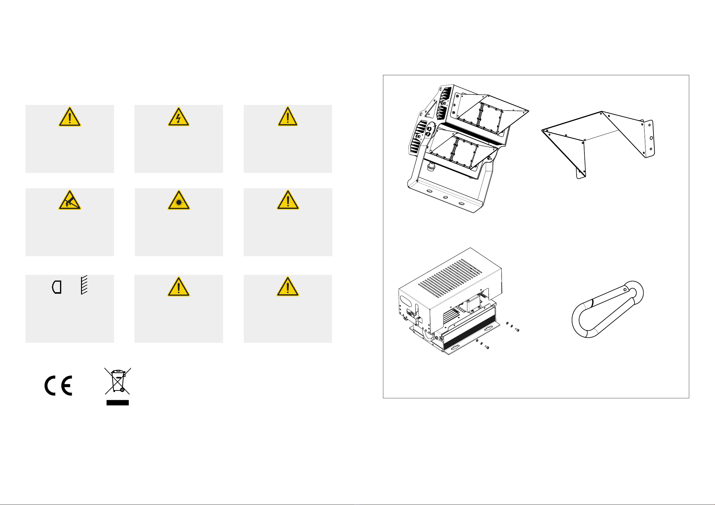
DRIVERS DRAWINGS, SCALE 1:5
Outdoor drive; Cabinet driver
is the same without metalwork
Visors to
be mounted
with 4x M6
screws each
along with
serrated
washers
SCALE 1:5
5. Visor mounting
Secure visors
Mount a visor on each LED module. The visor must be
secured with the supplied screws along with the serrated
washers as shown.
Tightening torque: 7-8 Nm.
The shape of the visors may vary.
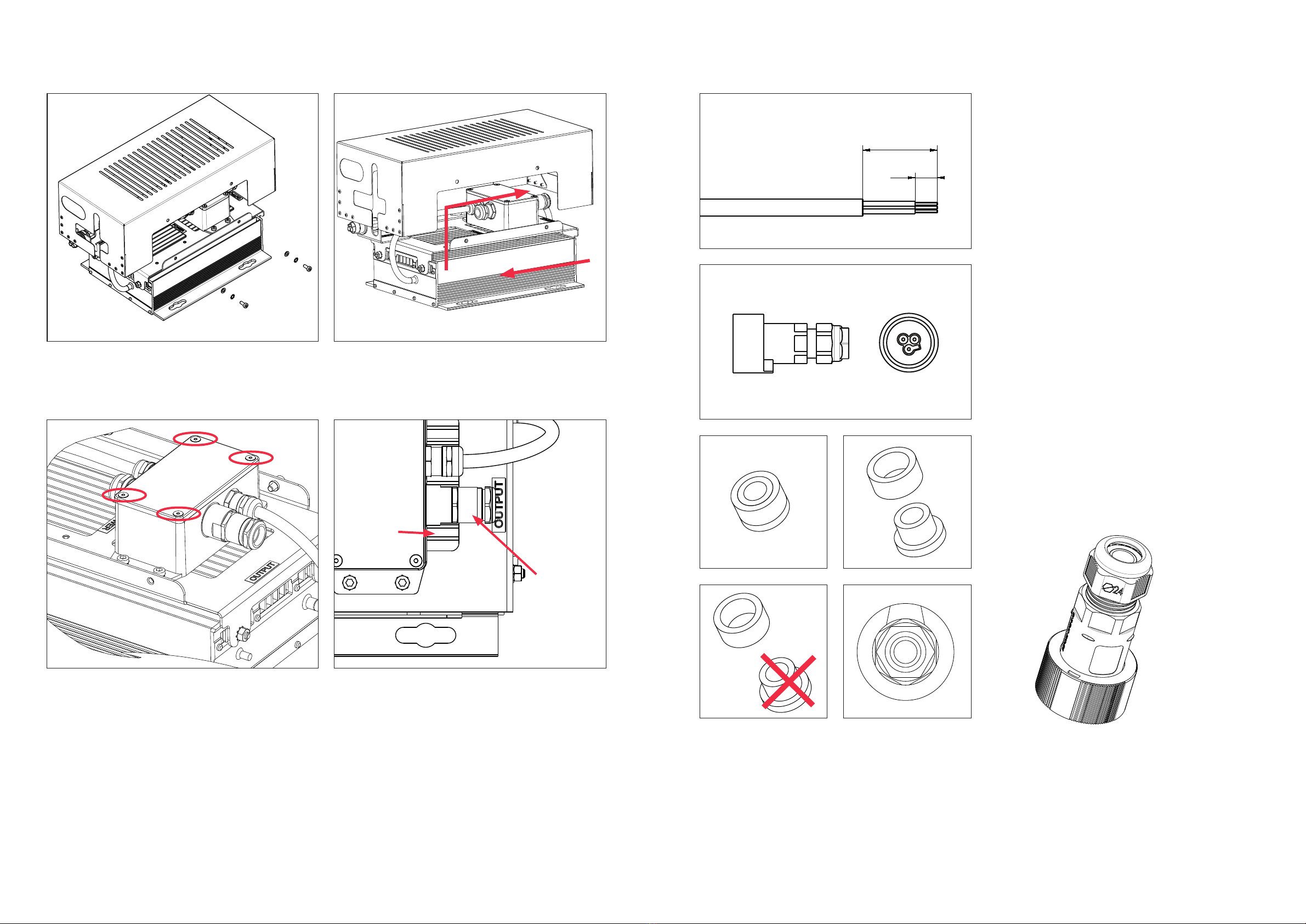
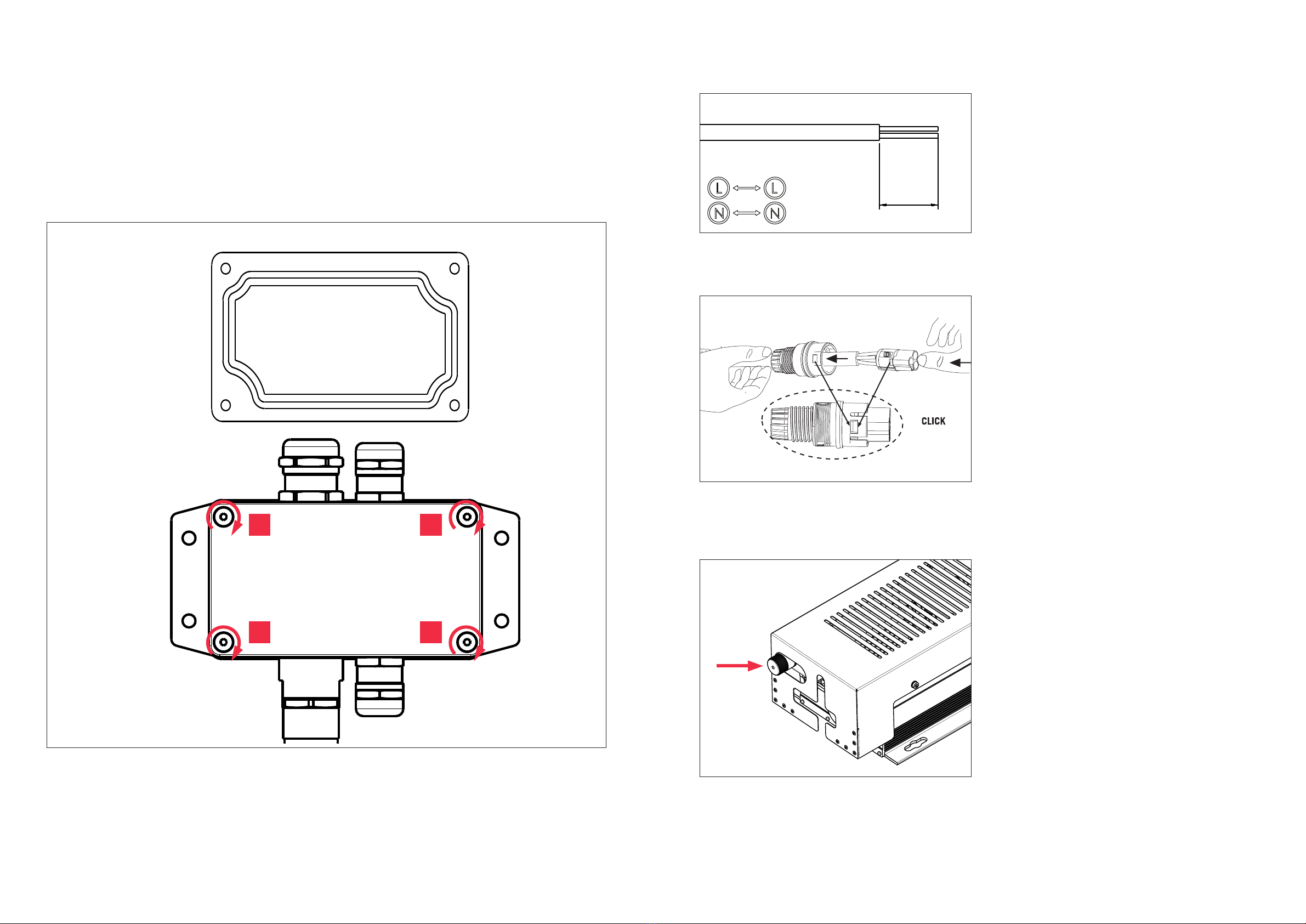
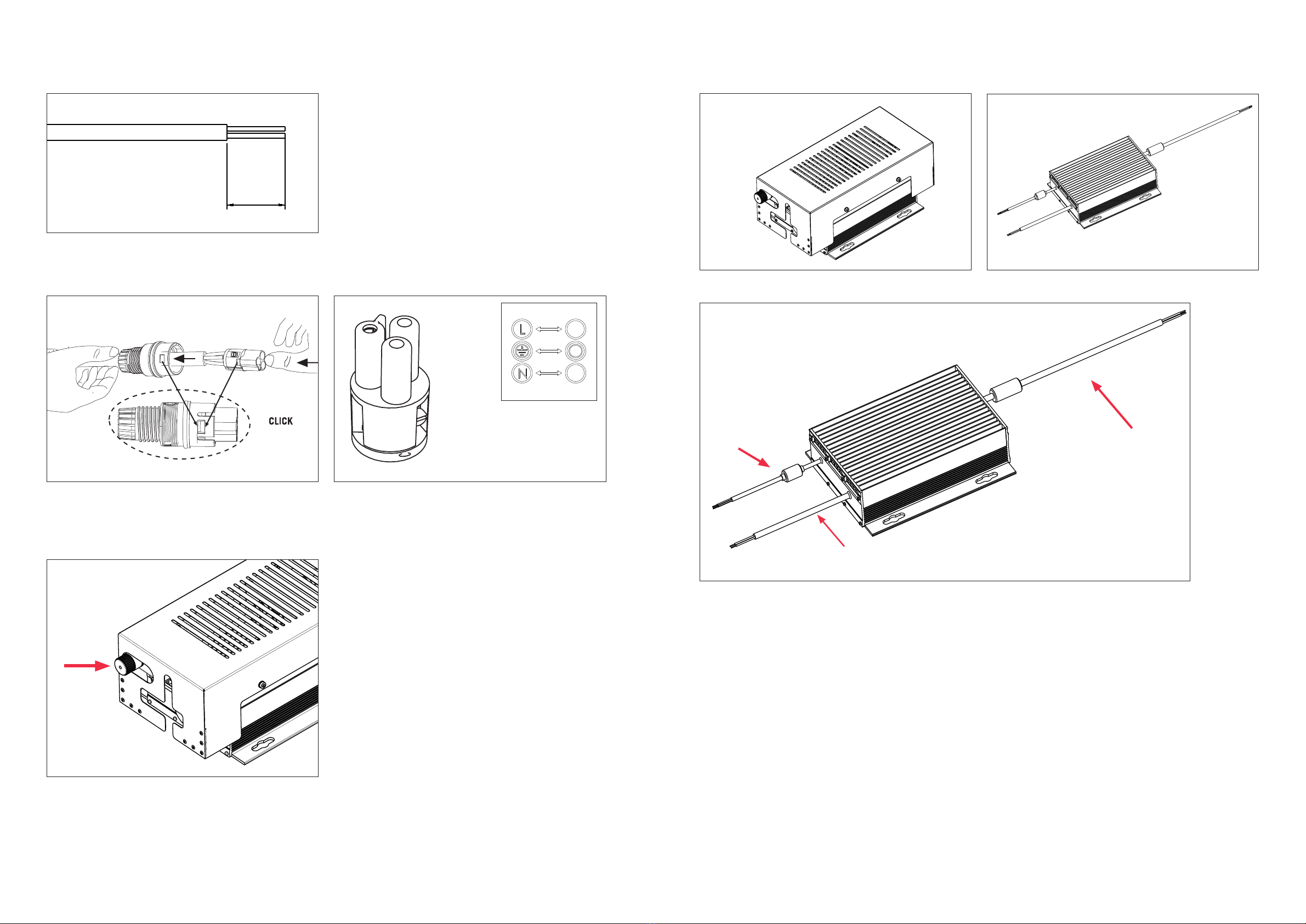
Securing the cable
The cables for the floodlight connection and power
connection must have 3 conductors (max. diameter
13 mm). Maximum conductors section is 1.5 mm2for
floodlight connector, 4 mm2for power connection).
Use a cable with 2 conductors for 0-10 V, DALI control
connection (max. diameter 12 mm).
On floodlights with an outdoor driver, secure the control
plug with the supplied closure cap when the control
system is not in use.
A Control cable – 0-10 V, DALI (not supplied)
B Mains cable – power connection (not supplied)
Important
Mount the shortest visor on the bottom module and the
longest visor on the top module, to avoid blocking light.
To protect the floodlight and its components and avoid
scratching, please lay the luminaire on the packaging
foam when mounting the visors or the bracket.
Flood light connection
(cable not supplied)
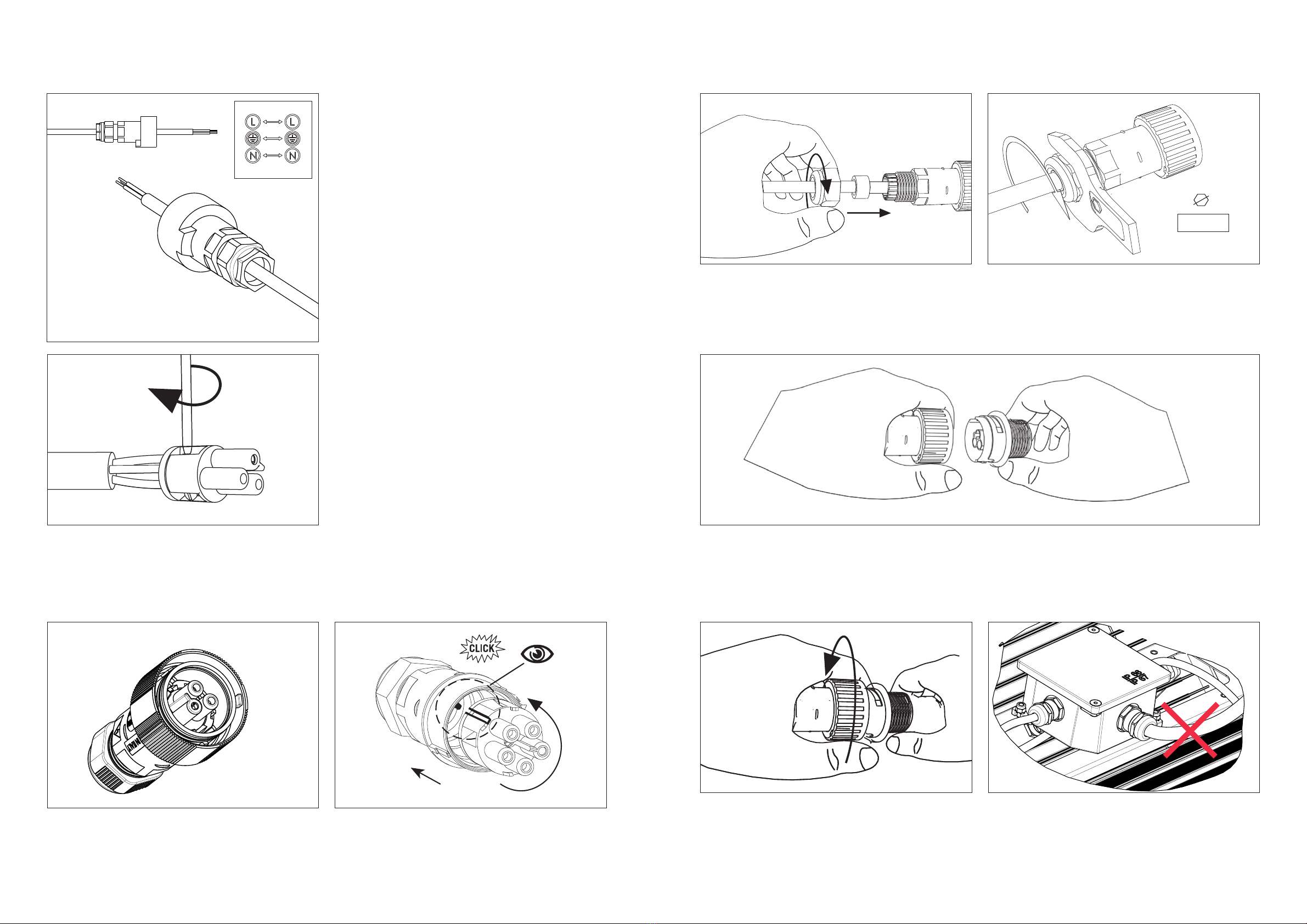
6. Electrical connection
Use a main circuit breaker
with a rated current of
at least 10A
Do not apply mains voltage
through the control system
cable. This will damage
the luminaire.
BA
2. Insert screws
Insert each screw with its plain washer and spring washer
through the central hole of the fitting bracket flange and
slightly tighten.
You will need to rotate the bracket with ease to adjust the
tilt.
4. Mounting
When the LED luminaire installation has been completed,
secure the floodlight to the mounting structure via the
safety cable.
Connect the safety cable to the holding frame with the
supplied carabiner hook.
1. Angled bracket
The floodlight is equipped with an angled bracket that
has a central hole for an M20 screw (tightening torque
250 Nm) and two slots for M16 screws -tightening
torque: 150 Nm.
3. Adjusting angle
The LED Luminaire can be tilted for ±20° using the scale
of 5° intervals when the longer notch sits in one of the
bottom land of the gear. If the bracket is rotated and the
shorter notch sits in one of the bottom land of the gear,
tilt has increased/decreased by 2,5°.
Once the tilting operation is complete, tighten and lock
the screws. Tightening torque: 60 Nm
5°
SCALE 1:4
SEE DETAIL A
Date Revision Sheet
MIDSTREAM LIGHTING LTD - 1 CHESHAM STREET - LONDON - SW1X 8ND - UNITED KINGDOM - Ph +44 207 584 8310
This drawing is property of MIDSTREAM LIGHTING Ltd. All rights reserved the partial or total reproduction of it is forbidden without express consent.
Drawing by Checked by Approved by
MIDSTREAMMC PC
HM = HIGH MAST
Eav = AVERAGE Lux LEVEL
u0= UNIFORMITY Emin / Eav
Total HM (All) - 8 with height of 16m Total Luminaires (All) - 16 x Modus S1100 MS
- 08 x Modus S1100 WS
2/3
00
06/04/2021
ML0556 - Hymers College - Mounting Instructions - Ref. to REV03 - Luminaire Details
horizontal reference
Visors parallel to
the ground: 0° tilt
Tilt is defined as
the angle between
the horizontal
reference and the
visors' edge
Fitting bracket has 2
holes that will set a
reference when aligned
to the longer notches
on the side of the
floodlight.
Those reference set the
tilt at 0°. Reference
notch can vary
according to mounting
layout.
SEE DETAIL A
SEE DETAIL B
The loop allows only
+/-20° tilts
2.5° resolution check
Range of tilt allowed is +/-20°
Every round sets a 5° interval, but resolution of bracket can be as
precise as 2,5°.
The angular rotation between a crest and a round is exactly 2,5°.
When the longer notch sits in a round, tilt is a multiple of 5°, but then
if the bracket is rotated to center the shorter notch in a round, tilt
has increased / decreased by 2,5°.
5°
5°
2.5°
Side View of the Luminaire with a Tilt
of 0.0°
DETAIL A
DETAIL B
6MODUS S INSTALLATION GUIDANCE
4. Bracket mounting and aiming
Use A2-80 stainless steel bolts or 8.8 class
steel bolts with hot dip galvanised coating
Do not use percussion drills

30
9
6a. Floodlight connection
Stripping the cable
Strip one end of the floodlight connection cable to a
length of circa 30 mm; then expose the conductors 9
mm.
(The cable from the driver to the floodlight is not supplied,
the cable used must be a rubber cable H05RN-F or
equivalent.)
The device has a type Y attachment. If it becomes
damaged it should only be replaced by the manufacturer
or by its service staff.
Take a TH405 Connector socket. The connector and its
housing are supplied in 2 pieces.
Adapting the grommet
Remove the inside part of the grommet, when the cable
diameter is greater than 9 mm. To remove the gasket,
remove cable gland nut first.
midstreamlighting.com call +44 (0) 207 584 8310
8 9
MODUS S INSTALLATION GUIDANCE
SCALE 1:1
SEE DETAIL A
6a. Floodlight connection - outdoor driver
Unscrew the cover
Unscrew the 4 M5 screws. Then remove the plastic cap from the connector plug, push towards the connector side
and take away the cover.
Connecting via cable gland
Remove the 4 countersunk screws to remove the junction box lid. Insert the cable through the cable gland. If the
connection requires a shielded cable, replace the cable gland with an EMC M20x1.5 one (NOT included in the
package). Use monkey pliers to hold the M20 adapter if it is necessary to remove the cable gland. Remove the cable
sheath for 65 mm to connect the wires with ease. WARNING: do not unscrew or remove the M20 adapter!
M20 adaptor
Cable gland

6a. Floodlight connection 6a. Floodlight connection
Inserting the terminal into the socket
Rotate the 3-pole terminal into the shown position to insert into the socket. Then push and rotate counter-clockwise
until you hear a click. The click means the terminal is properly locked into the socket.
Connect the plug and socket
Connect the plug to the socket. The arrow on the plug and the arrow on the socket must face each other.
Secure the connection
Rotate the outer part of the socket clockwise, then
push the red clip to the locked position to secure the
connection. If unlocking is required, use a screwdriver to
pull the clip to an unlocked position.
Warning
Do not pull the cables during installation. Do not bend the
cables more than the minimum bending radius - 5 to 8
times of the diameter of the cable.
Stripping the cable
Insert the cable through the connector housing.
The socket has L, N, earth symbols. Match as follows:
Live BROWN wire
Neutral BLUE wire
Earth symbol YELLOW/GREEN wire.
Insert the exposed wires in the plug and tighten each
screw.
Pull the wires to check if they are well tightened
Tighten the nut
Tighten the plastic nut with a 24 mm wrench key.
midstreamlighting.com call +44 (0) 207 584 8310
10 11
MODUS S INSTALLATION GUIDANCE
SCALE 2:1
XSEC0001-XSEC0001SECTION
CH24mm
Nm2.5÷4
SCALE 1:2
SEE DETAIL
A

Driver
INPUT
cable
Driver
OUTPUT
cable
Driver INPUT cable
(to driver)
Output cable
(to floodlight)
Driver OUTPUT
cable
(from driver)
PRODUCED BY AN AUTODESK STUDENT VERSION
51
60
PRODUCED BY AN AUTODESK STUDENT VERSION
Driver INPUT cable
(to driver)
Output cable
(to floodlight)
Driver OUTPUT
cable
(from driver)
Mains
input
cable
Remove the cable sheath for a length of 60 mm, expose
the conductor for 9 mm and insert the mains cable
through the cable gland without the adapter. Connect
the YELLOW-GREEN wire to the 5-way WAGO terminal.
Close the void position as well, even if there is no wire
connected. Connect the BROWN wire to the 2-way
WAGO terminal that has already a brown wire with an
“L” sticker. Connect the BLUE wire to the 2-way WAGO
terminal that has already a blue wire with an “N” sticker.
Tighten the M20 cable glands (torque: 8 Nm).
midstreamlighting.com call +44 (0) 207 584 8310
12 13
MODUS S INSTALLATION GUIDANCE
6a. Floodlight connection - Outdoor driver 6b. Power supply connection - Outdoor driver
Connecting the WAGO terminals
Connect the YELLOW-GREEN wire to the 5-way WAGO terminal.
Connect the BROWN wire to the WAGO terminal that has already a brown wire with a “+” sticker. Connect the BLUE
wire to the WAGO terminal that has already a blue wire with a “-” sticker.

Gasket must be properly
positioned to create seal
6b. Power supply connection - Outdoor driver 6c. Control connection - DALI - Outdoor driver
Checking the gasket
Check the gasket is properly positioned inside the lid, then close the junction box.
Secure it with 4 countersunk screws (tighten them in the order shown).
WARNING: if the gasket is wrongly positioned or screws are loose water may get into the junction
box.
Place the cover back on to the driver unit and the cap on the control plug if not needed.
Strip the rubber jacket of the cable, expose 25 mm of
conductors. Mount the TH384 – socket connector.
Match
L RED conductor (+ pole / DA)
N BLUE conductor (- pole / DA).
Tighten the screws and pull each wire to check if they are
well clamped. Conductor colours may vary.
Remove the plastic cap to plug the control cable (2 poles,
yellow connector).
Insert the socket into the connector housing. Tighten the
plastic nut to seal the cable with the connector grommet.
1
3
4
2
midstreamlighting.com call +44 (0) 207 584 8310
14 15
MODUS S INSTALLATION GUIDANCE
25

6d. Cabinet driver
6c. Control connection 0-10V - Outdoor driver
Strip the rubber jacket of the cable, expose 25 mm of
conductors. Mount the TH384 – socket connector.
Match
L BROWN conductor (Dimming +
pole)
N BLUE conductor (Dimming - pole)
Ground pole with the 12 V+ wire.
Tighten the screws and pull each wire to check if they are
well clamped. Conductor colours may vary.
Remove the plastic cap to plug the control cable (3 poles,
white connector).
Insert the socket into the connector housing. Tighten the plastic nut to seal the cable with the connector
grommet.
midstreamlighting.com call +44 (0) 207 584 8310
16 17
MODUS S INSTALLATION GUIDANCE
25
Dim
+
Dim
-
12v
Outdoor layout
INPUT cable: this cable power supplies the driver. Its 3 wires have to match these connections:
Brown L / L1
Blue N / L2
Yellow&Green Ground
OUTPUT cable: this cable power supplies the floodlight. This cable has 2 wires: brown (+) and blue (-). The
connection has to be done in such a way that the 2 wires match these poles on the floodlight connector on the top of
the mast:
Brown L
Blue N
OUTPUT cable: this cable power supplies the floodlight. This cable has 2 wires: brown (+) and blue (-). The
connection has to be done in such a way that the 2 wires match these poles on the floodlight connector on the top of
the mast:
Purple Dimming +
Grey Dimming -
Black&White 12 V Auxiliary output voltage (only if needed)
Cabinet layout
Input cable (mains)
Control cable
Output cable

7. Electrical specications 9. Dimensions
8. Weight and windage
Modus S 900 Modus S 1100
Input Voltage 200-480 Vac 200-480 Vac
Input Frequency 50 – 60 Hz 50 – 60 Hz
Absorbed Power 999 W 1180 W
Power Factor 0.97 0.97
Inrush Current (I2t) 37.5 A2s - for 1.18 ms* 37.5 A2s - for 1.18 ms*
Modus S Outdoor driver Cabinet driver
Weight 20kg 9kg 6.5kg
Windage 0.203m2- -
* at 220 V ac input, 25°C cold start, 10% Ipk – 10% Ipk
Modus S Floodlight
Modus S – Outdoor driver (cabinet driver is the same without metalwork: 280 x 230 x 76 mm)
midstreamlighting.com call +44 (0) 207 584 8310
18 19
MODUS S INSTALLATION GUIDANCE
478
432
593
398
152
230
182
202
176
16
96.2
30
90 17
21
SCALE 1:5
478
432
593
398
152
230
182
202
176
16
96.2
30
90 17
21
SCALE 1:5
478
432
593
398
152
230
182
202
176
16
96.2
30
90 17
21
SCALE 1:5
478
432
593
398
152
230
182
202
176
16
96.2
30
90 17
21
SCALE 1:5
478
432
593
398
152
230
182
202
176
16
96.2
30
90 17
21
SCALE 1:5
478
432
593
398
152
230
182
202
176
16
96.2
30
90 17
21
SCALE 1:5

2020
For translations, digital versions or more information please head to
www.midstreamlighting.com/installation-guides
European HQ
Midstream Ltd. Wessex House, 1 Chesham Street, London SW1X 8ND, United Kingdom
US HQ
Midstream Lighting Ltd. 66 West Flagler Street, Miami, FL 33130, USA
midstreamlighting.com
This manual suits for next models
2
Table of contents
Other Midstream Lighting Equipment manuals
Popular Lighting Equipment manuals by other brands

Exor
Exor CDW12U5 Installation and commissioning instructions

North Light
North Light WX-31VLED44-150MC-10-1 Instructions for use

FormaLighting
FormaLighting 6530 Installation instruction

GOAL ZERO
GOAL ZERO Light-A-Life mini user manual

ecoStage
ecoStage C-1915 user manual

Expolite
Expolite TourLED 21 CM MKII user manual