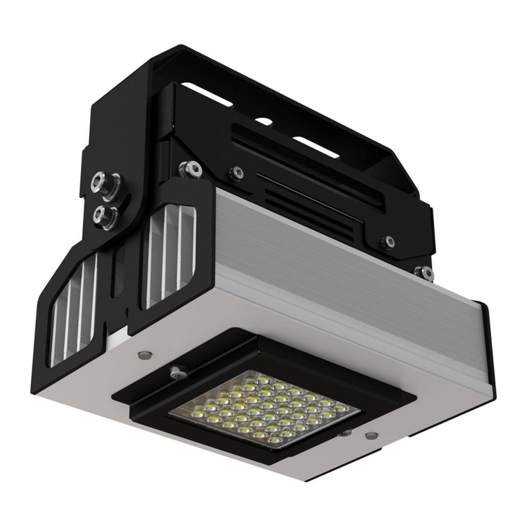
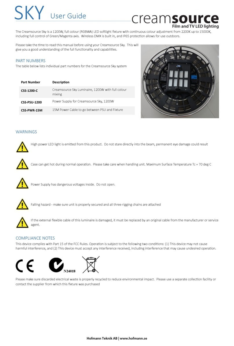
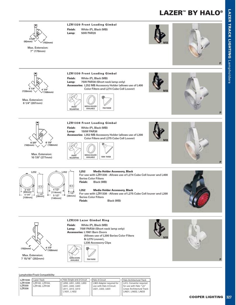
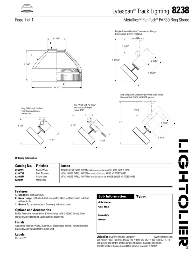
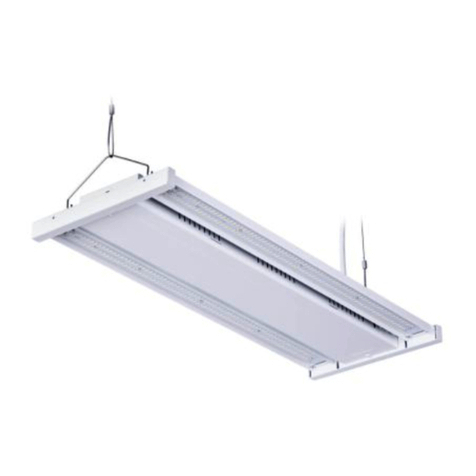
Midstream Modus 450 User manual

Modus 450
INSTALLATION GUIDANCE

midstreamlighting.com call +44 (0) 207 584 8310
2 3
MODUS 450 INSTALLATION GUIDANCE V1
Contents
Prior to starting the installation, check the equipment list
to be sure of using the correct tools
DO NOT USE PERCUSSION DRILLS!
30 mm standard wrench for M20 screws
21 mm standard wrench for connector cables
19 mm standard wrench for M12 screws
#8 allen key
#6 allen key
Powered drill-screwdriver with adjustable torque
(clutch)
Torx T30 insert bit for powered screwdriver (to be
used with M6 screws)
Torx T30 manual screwdriver
Monkey pliers
Electrician scissors for wires
Slotted manual screwdriver for connector’s screws
(blade dimensions: 3.5(w) x 0.6 mm)
Equipment list
Wear adequate working gloves, safety shoes and
hard hats to protect yourself from falling material
Never energize the lamp if wiring operation is not
completed
H&S check
1. General notes
Section PAGE
1 General notes 3
2 Safety instructions 4
3 Contents 5
4 Bracket mounting and aiming 6
5 Visor mounting 7
6 Electrical connection 7
7 Electrical specifications 10
8 Weight and Windage 10
9 Dimensions 11
This user manual contains important information on safe operation of the Luminaire.
Read and follow all safety notes and all instructions. Save this manual for future reference.
Make sure that it is available to all persons using this device.
All wiring should be done by a licensed electrician in accordance with state codes, local codes, and National Electric
Code (NEC) standards or International Electrotechnical Commission (IEC) standards.
The Luminaire is suitable for out door use and wet locations.
This luminaire must only be replaced by the manufacturer, by its service staff or by qualified personnel.
IP66: The product is protected against powerful water jets.
DO
Store the luminaire with care, avoiding placing the lenses on the ground, which may scratch or damage them
Keep the luminaire in the original packaging when storing to avoid damage
When handling the Luminaire, wear industrial safety gloves and safety boots
Operate on circuitry when the electrical power supply is disconnected
DO NOT
Do not apply mains voltage through the control system cable. This will damage the luminaire and it will no longer
be covered by warranty
Do not unnecessarily remove the luminaire from the box
Do not leave the LED luminaire switched on when resting on the ground with optics facing down
Do not place the luminaire with the lens on the ground, dirty or metal surfaces
Do not clean the lenses with any industrial detergent. Only use a water-soaked cloth if needed

2. Safety instructions
Use the device only as described in this user manual.
Any other use or use under other operating conditions
is considered to be improper and may result in personal
injury or property damage as well as voiding the warranty.
No liability will be assumed for damages resulting from
improper installation.
This product meets all legal requirements for UKCA and CE marking.
This device is subject to the European directive 2002/96/EC.
Do not dispose of the device with your normal household waste. Dispose of this
device through an approved waste disposal firm or through your local waste
facility. Comply with the rules and regulations that apply in your country. If in doubt,
consult your local waste disposal facility.
Only persons with sufficient physical, sensorial, and
intellectual abilities and that have corresponding
knowledge and experience may operate this device.
Contains parts and
assemblies susceptible to
damage by electrostatic
discharge (ESD)
The luminaire should be
positioned so that prolonged
staring into the luminaire at
a distance closer than 4m
(13 ft) is not expected
The light source of this
appliance must only be
replaced by the manufacturer,
its after-sales service or
qualified personnel
The minimum safety distance
from illuminated object to
avoid any damages is 1 m
The luminaire is not to be
placed face down on any
surface other than the
provided foam pad
Risk of electric shock
Disconnect the electrical
power supply before
commencing the installation:
failure to do so could result in
serious injury
Hard Hats, Safety shoes,
Hi-Vis vest and Safety
Gloves must be worn
at all times
Do not power the luminaire
with a generator
Two persons
required to complete
the installation
1m
Waiver: This document represents information compiled to the best of our present
knowledge. It is not intended to as a representation or warranty of fitness of the
products described for any particular purpose. This document details guidelines
for general information purposes only. Always seek specialist advice when planning
installations and ensure the installation is carried out by a properly qualified
installer.
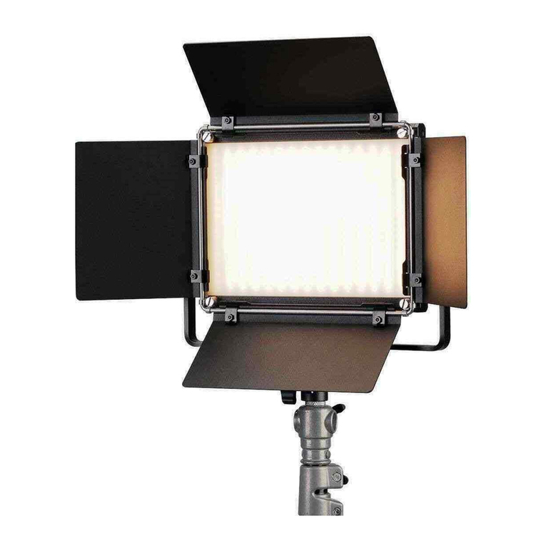
Modus 450 LED luminaire
Visor with screws and washers Caribiner hook and saftey
cable
3. Contents
4MODUS 450 INSTALLATION GUIDANCE
Main cable and control cable Mounting screws and nuts
Not supplied

2. Insert screws
Insert each screw with its plain washer and spring washer
through the central hole of the fitting bracket flange and
slightly tighten.
You will need to be able to rotate the bracket with ease to
adjust the tilt.
4. Mounting
When the LED luminaire installation has been completed,
secure the floodlight to the mounting structure via the
safety cable.
Connect the safety cable to the holding frame with the
supplied carabiner hook.
1. Angled bracket
The floodlight is equipped with an angled bracket that
has a central hole for an M20 screw (tightening torque
250 Nm) and two slots for M12 screws (tightening torque:
80 Nm). Bracket has 2 positioning layouts.
3. Adjusting angle
The LED luminaire can be tilted at 5° intervals using the
notches on the frame and the references on the bracket.
Once the tilting operation is complete, tighten and lock
the screws (tightening torque: 50 Nm).
5°
5°
56.0 1
A 3.00
22.0 2
A 3.00
22.0
3
A 3.00
56.0
4
A 3.00
SCALE 1:1
SEE DETAIL A
midstreamlighting.com call +44 (0) 207 584 8310
6 7
MODUS 450 INSTALLATION GUIDANCE
4. Bracket mounting and aiming
Use A2-80 stainless steel bolts or 8.8 class
steel bolts with hot dip galvanised coating
Do not use percussion drills
4.9°
5°
56.0 1
A 3.00
22.0 2
A 3.00
22.0
3
A 3.00
56.0
4
A 3.00
SCALE 1:1
SEE DETAIL A
5. Visor mounting
Secure visor
Mount the visor on the LED module. The
visor must be secured with the supplied
screws along with the serrated washers
as shown.
Tightening torque: 7-8 Nm.
The shape of the visors may vary.
Power plug
The cable for floodlight power connection must have
3 conductors (max. diameter 12 mm, max. section
1,5 mm2). This should be connected to the white plug
labelled 'power'.
Control plug
Use a cable with 2 conductors for DALI control
connection (max. diameter 12 mm, max section 1,5
mm2). This should be connected to the yellow plug,
labelled 'control'.
Use a cable with 3 conductors for 0-10 V control
connection (max. diameter 12 mm, max section 1,5
mm2).
This should be connected to the white plug, labelled
'control'.
6. Electrical connection
Use a main circuit breaker
with a rated current of
at least 16 A
Do not apply mains voltage
through the control sytem
cable. This will damage
the luminaire.
Control
connector
yellow (DALI),
or white (0-10V).
Keep closed
with cap if
not in use
Power
connector
(white)

Tighten the nut
Tighten the nut using a 21 mm wrench
Connect the power cable
Connect the socket to the plug on the LED luminaire and
tighten the housing to ensure IP68 protection. Test the
luminaire before attaching it to the final connection point.
Connect the power cable to the connector with 'POWER'
sticker on it, and control cable to the connector with
'CONTROL' sticker on it.
midstreamlighting.com call +44 (0) 207 584 8310
8 9
MODUS 450 INSTALLATION GUIDANCE
6. Electrical connection 6. Electrical connection
Connector mounting
To mount the connector on the cable, remove the cable sheath for 25 mm. The wires do not need to be stripped
because the connector is equipped with piercing screws. If the cable diameter is great than 9 mm remove the inside
part of the grommet. To remove the gasket, remove cable gland nut first. Insert the cable through the socket housing
of the connector.
Wiring instructions
Insert each wire into the socket terminal, matching wire
colour with the 'L', 'N' and 'GND' symbol on the socket
and tighten the screws. Match:
Mains cable
Live BROWN wire
Neutral BLUE wire
Earth symbol YELLOW/GREEN wire.
Dali control cable
Live DALI+
Neutral DALI-
0-10 V control cable
Live Control+
Neutral Control-
Earth symbol 12V aux (only if needed)
Insert the socket into the housing until the inner part
'clicks' in and then insert the gasket.
Self-piercing
DA1
DA2
+
+
=
DA1
DA2
+
+
=
DALI control 2 pole
0-10V control
and power 3 pole

7. Electrical specications 9. Dimension
8. Weight and windage
Modus 450 0-10V Modus 450 DALI
Input Voltage 90-305 V ac 180-528 V ac
Input Frequency 50 – 60 Hz 50 – 60 Hz
Absorbed Power 450 W 450 W
Power Factor 0.97 0.98
Inrush Current 2.8 A2s - for 5.6 ms* 40 A - for 1.1 ms**
Modus 450
Weight 13.5 kg
Windage EPA 0.13m2
* at 480 V ac input, 25°C cold start, measured at 50% Ipk
** at 220 V ac input, 25°C cold start, 10% - 10% Ipk
This device is subject to the European directive 2002/96/EC.
Do not dispose of the device with your normal household waste.
Dispose of this device through an approved waste disposal firm or through your local waste facility.
When discarding the device, comply with the rules and regulations that apply in your country.
If in doubt, consult your local waste disposal facility.
midstreamlighting.com call +44 (0) 207 584 8310
10 11
MODUS 450 INSTALLATION GUIDANCE
219mm
202mm 434mm

2020
For translations, digital versions or more information please
head to https://www.midstreamlighting.com/installation-guides
European HQ
Midstream Lighting Ltd. Wessex House, 1 Chesham Street, London SW1X 8ND, United Kingdom
US HQ
Midstream Lighting Ltd. 66 West Flagler Street, Miami, FL 33130, USA
midstreamlighting.com
Table of contents
Other Midstream Lighting Equipment manuals
