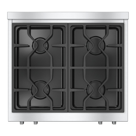
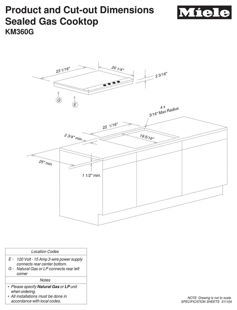
Miele KM 34 Series Manual

TECHNICAL INFORMATION
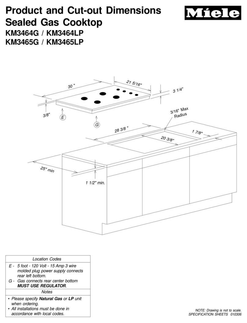
KM 34xx Gas Cooktops
© 2011 Miele USA

Technical Information
2
KM 34xx Gas Cookto
p
s
Table of Contents
AWarning and Safety Instructions ............................................................4
1General Information......................................................................................... 4
2Touch Current Measurement ..........................................................................4
3Gas..................................................................................................................5
BModification History.................................................................................5
CTechnical Data..........................................................................................6
DLayout of Electrical Components ...........................................................8
010Cooktop.....................................................................................................9
1Technical Data ..............................................................................................10
2Function.........................................................................................................10
2.1Rapid Ignition..................................................................................... 10
2.2Thermocouple....................................................................................10
2.3 Automatic Re-Ignition ........................................................................10
3Fault Repair................................................................................................... 11
3.1Flame Does Not Ignite.......................................................................11
3.2Burners Do Not Light .........................................................................11
3.3Burners Do Not Light - No Gas Supply..............................................11
3.4Flame Goes Out at the Minimum Setting...........................................11
3.5Burner Ignites Automatically During Use ...........................................12
4Service ..........................................................................................................13
4.1Cooktop Surface Removal.................................................................13
4.3Gas Type (Jet) Conversion................................................................14
4.4Main Jet Replacement.......................................................................15
4.5Thermocouple (Flame-Monitoring Electrode) Removal .....................17
4.5.1Normal/Fast Burners..............................................................17
4.5.2Wok Burners ..........................................................................17
4.6Ignition Electrode Removal................................................................18
4.6.1Normal/Fast Burners..............................................................18
4.6.2Wok Burners ..........................................................................18
4.7Burning Properties Test.....................................................................19
4.7.1Normal/Fast Burners..............................................................19
4.7.2Wok Burners ..........................................................................19
4.8 Thermocouple Test............................................................................20
4.9Automatic Re-Ignition Test ................................................................20
020Burner Tap..............................................................................................21
4Service ..........................................................................................................22
4.1Switch Removal.................................................................................22
4.2Simmer Adjustment Jet Replacement ...............................................22
4.3Solenoid Removal..............................................................................23
4.5 Electronics Removal ..........................................................................23
4.6Transformer Removal ........................................................................ 24
4.7Terminal Block Removal....................................................................24
4.8Leakage Test.....................................................................................25
4.9Solenoid Continuity Check.................................................................25
Technical Information
3
KM 34xx Gas Cookto
p
s
List of Figures
Figure D-1: KM 34xx Components (KM 346x Shown) ............................................................8
Figure 010-1: Wok Burner Components ...............................................................................14
Figure 010-2: Normal/Fast Burner Components ...................................................................14
Figure 010-3: Main Jet on Normal/Fast Burner.....................................................................15
Figure 010-4: Main Jet - Outer Flame Ring (Wok Burner) ....................................................16
Figure 010-5: Main Jet - Inner Flame Ring (Wok Burner) .....................................................16
Figure 010-6: Thermocouple Removal on Normal/Fast Burners ..........................................17
Figure 010-7: Thermocouple Removal, Wok Burners...........................................................18
Figure 010-18: Flame Settings, Normal/Fast Burners...........................................................19
Figure 010-17: Inner and Outer Flame Ring Settings (Wok Burners) ...................................20
Figure 020-1: Simmer Adjustment Jets, Wok Burner Shown................................................22
Figure 020-2: Solenoid Removal...........................................................................................23
Figure 020-3: Electronics Removal .......................................................................................23
Figure 020-4: Transformer Removal .....................................................................................24
Figure 020-5: Terminal Block Removal.................................................................................24
List of Tables
Table C-1: Data Sheet ............................................................................................................6
Table C-2: Jet Table for Natural and Liquid Gases, Wok Burners ..........................................7
Table C-3: Jet Table for Natural and Liquid Gases, Normal/Fast Burners..............................7
Table 010-1: Air Setting for Main Jets on Wok Burners ........................................................10

Technical Information
4
KM 34xx Gas Cookto
p
s
A Warning and Safety Instructions
1 General Information
Service and repair work should only be carried out by a suitably qualified
electrician (with specialist training, knowledge and experience, and recent
related work experience) in accordance with all appropriate local and national
safety regulations.
Servicing, modification, testing and maintenance of electrical appliances
should only be carried out in accordance with all appropriate legal
requirements, accident prevention regulations and valid standards.
Unless absolutely necessary, e.g., fault finding with supply voltage, working
on a machine connected to the power supply should always be avoided. If
working on a machine with an applied voltage at a potentially dangerous level
is unavoidable, special safety measures must be taken into consideration and
complied with.
Before starting any service work, the machine must be disconnected from the
power supply. Suitable measurements must be made to ensure that this is
the case.
Even with the machine switched off, voltage may be applied to some
components.
A general visual check should always be carried out.
There may be a risk of injury due to protruding parts. Protective goggles
should be worn.
There may be a risk of injury due to sharp edges. Protective gloves should be
worn and the edge protection, mat. no. 05057680, should be used.
2 Touch Current Measurement
Note:
On machines with a ground connection, touch current leakage
measurements should be carried out on all accessible conductive parts that
are not connected to ground.
Warning!
Touch current measurement should only be carried out after the ground
connection of the appliance under test has been checked and found to be
satisfactory! Dangerous voltages may exist on defective machines as well as
on accessible conductive parts that are not connected to ground!
Note:
Touch current measurement should be carried out on the following
accessible conductive parts:
None.

Technical Information
5
KM 34xx Gas Cookto
p
s
3 Gas
Danger!
These machines should not be installed or operated in any area where there
is a risk of explosion. Before starting any service work, disconnect the gas
safety socket (if it has an additional tap, this must also be closed) or close
the tap on a fixed connection.
If the gas supply is to be disconnected, the following must be complied with:
On cooktops with a gas safety socket, disconnect the gas safety hose.
On cooktops with a fixed gas connection with tap, install a stopper on
the gas pipe after disconnection and ensure that it is properly sealed.
Closing the tap alone is not sufficient.
Note:
Service and repair work should only be carried out by suitably qualified
persons in accordance with all appropriate local and national safety
regulations. Ensure that all special regulations applying to gas installations
and different types of gas are also complied with.
B Modification History
When? Who? What?
4/11/2011 Jessica Naples Compilation for Website

Technical Information
6
KM 34xx Gas Cookto
p
s
C Technical Data
Models KM 346x G KM 347x G KM 348x G
Appliance dimensions
Width 30.0” 36.0” 42.5”
Depth 21.3” 21.3” 21.3”
Cutout dimensions
Width 28.3” 35.0” 41.5”
Depth 20.4” 20.4” 20.4”
Built-in height with gas connection 3.3” 3.4” 3.4”
Controls
Switch knobs Yes Yes Yes
Rapid ignition Yes Yes Yes
Electrical ignition/one-hand control Yes/Yes Yes/Yes Yes/Yes
Frame Stainless steel Stainless steel Stainless steel
Heating Gas Gas Gas
Burner type (power level)
One wok (0.2 to
4.5 kW), two
normal (0.5 to 2.6
kW), one fast (0.7
to 3.5 kW)
Two wok (0.2
to 4.5 kW), two
normal (0.5 to
2.6 kW), one
fast (0.7 to 3.5
kW)
Two wok (left
0.2 to 4.5 kW
and right 0.2 to
4.8 kW), two
normal (0.5 to
2.6 kW), two
fast (0.7 to 3.5
kW)
Features
Safety cut-out Yes Yes Yes
Thermoelectric ignition control
(thermocouple) Yes Yes Yes
Automatic re-ignition Yes Yes Yes
Natural gas-compatible Yes Yes Yes
Liquid gas-compatible Yes Yes Yes
Accessories
Cable with plug Yes Yes Yes
Wok ring Yes Yes Yes
Jet set for liquid gas Yes Yes Yes
Gas connection – US models only
Rated load (maximum output) 13.2kW 17.7kW 21.5kW
Electrical connection – US models only
Voltage 120VAC 60Hz 120VAC 60Hz 120VAC 60Hz
Rated load < 0.025 kW < 0.025 kW < 0.025 kW
Fuse rating 15A 15A 15A
Interference-free power supply Yes Yes Yes
Interference suppression Yes Yes Yes
Table C-1: Data Sheet
The cooktop is suitable for operation with natural gas or liquid gas.

Technical Information
7
KM 34xx Gas Cookto
p
s
Jet diameters, wok burners
Diamete
r
1
Gas type Main jet - inner
flame ring Main jet - outer
flame ring Simmer adjustment jet
Natural gas 0.60mm
1.90mm (KM 346x
and KM 347x) 0.88mm2/0.40mm3
1.95mm (KM 348x)
Liquid gas 0.29mm
1.09mm (KM 346x
and KM 347x) 0.54mm2/0.25mm3
1.12mm (KM 348x)
Table C-2: Jet Table for Natural and Liquid Gases, Wok Burners
1 Jet hole diameters are usually marked on the jet in 1/100 mm (e.g., 62, 77, etc.).
2Simmer adjustment jet for outer flame ring
3 Simmer adjustment jet for inner flame ring
Jet diameters, normal/fast burners
Diameter1
Gas type Main jet Simmer adjustment jet
Natural gas 1.40mm2/1.67mm30.62mm2/0.78mm3
Liquid gas 0.9mm2/1.03mm30.41mm2/0.45mm3
Table C-3: Jet Table for Natural and Liquid Gases, Normal/Fast Burners
1 Jet hole diameters are usually marked on the jet in 1/100 mm (e.g., 62, 77, etc.).
2Normal burner
3Fast burner

Technical Information
8
KM 34xx Gas Cookto
p
s
D Layout of Electrical Components
Figure D-1: KM 34xx Components (KM 346x Shown)
1 Electronic 8Ignition electrode, wok burner
2 Ignition transformer 9 Flame monitor electrode
(thermocouple), wok burner
3 Terminal block 10 Solenoid
4 Normal burner 11 Switch
5 Ignition electrode, normal burner 12 Fast burner
6 Flame monitor electrode
(thermocouple), normal burner
13 Ignition electrode, fast burner
7 Wok burner 14 Flame monitor electrode
(thermocouple), fast burner

Technical Information
9
KM 34xx Gas Cookto
p
s
010 Cooktop
KM 3475 G Shown

Technical Information
10
KM 34xx Gas Cookto
p
s
1 Technical Data
Gap X for air setting (mm)
Gas type Outer flame ring Inner flame ring
Natural gas 6 2
Liquid gas 13 2
Table 010-1: Air Setting for Main Jets on Wok Burners
2 Function
2.1 Rapid Ignition
With rapid ignition, it is no longer necessary to hold the switch knob pressed in at
the largest flame setting until the thermocouple is sufficiently heated. The switch
knob can immediately be set to any desired flame setting and released.
The built-in electronic makes rapid ignition possible. As soon as the switch on the
burner tap is activated, the electronic applies a voltage of approximately 65 volts
DC (attraction voltage) to the electromagnet solenoid for 100 milliseconds.
The solenoid valve then opens the gas path.
At the same time, the electronic activates the ignition transformer, the ignition
spark is developed and the flame is ignited. When the thermocouple has heated
sufficiently, it applies the necessary holding voltage of 0.8 volts DC to the
solenoid and the gas path remains open.
2.2 Thermocouple
Flame monitoring and ignition control of each burner is via a thermocouple. The
thermocouple is heated by the flame and a thermoelectric effect produces a
voltage signal which is passed to the electronic. This then provides a holding
voltage of 0.8 volts DC which is applied to the solenoid to keep the gas path
open.
If the thermocouple cools, the holding voltage is no longer applied to the solenoid
and the automatic re-ignition cycle starts; see Section 010-2.3.
2.3 Automatic Re-Ignition
If the flame is extinguished for some reason, e.g., due to a draft of air or water
splash, the thermocouple cools. This is registered by the electronic, which then
acts to try to ignite the flame again. If the re-ignition attempts are not successful
within 10 seconds, the gas path to the burner is closed.

Technical Information
11
KM 34xx Gas Cookto
p
s
3 Fault Repair
3.1 Flame Does Not Ignite
Cause:
No ignition spark.
Remedy:
1. Check the ignition electrode. Replace it, if necessary; see Section 010-4.6.
2. Check the transformer. Replace it, if necessary; see Section 020-4.6.
3.2 Burners Do Not Light
Cause:
Ignition electrode is dirty or defective.
Remedy:
Check the ignition electrode. Clean or replace as necessary; see Section 010-4.6.
3.3 Burners Do Not Light - No Gas Supply
Turning the switch knobs produces ignition sparks, but the gas supply is not
opened. All burners are affected. The operational indicator blinks or flashes in the
display, if applicable.
Cause:
Gas tap is closed.
Remedy:
Open the gas tap.
Cause:
After connecting, there is still air in the gas pathway.
Remedy:
Ignite the burners again.
Cause:
The installed jets are not appropriate for the gas type used.
Remedy:
Check the jets. Convert them for gas type, if necessary; see Section 010-4.3.
3.4 Flame Goes Out at the Minimum Setting
Cause:
Burner cap seated incorrectly.
Remedy:
Seat the burner cap correctly.
Cause:
Burner components are dirty.
Remedy:
Clean the burner components.
Cause:
Draft from an open window.
Remedy:
Close the window.

Technical Information
12
KM 34xx Gas Cookto
p
s
Cause:
Burner cap is skewed. Burner cap must sit evenly on the burner head.
Remedy:
Check for distortions in the burner cap. Replace the burner cap, if necessary.
Cause:
Thermocouple is dirty.
Remedy:
Clean the thermocouple.
Cause:
Thermocouple is crooked.
Remedy:
Bend the thermocouple using a tubular socket wrench so that it is perpendicular
to the base.
Cause:
Thermocouple is defective.
Remedy:
1. Pull on the thermocouple's inside wire to make sure that it is secure inside
the thermocouple.
2. If this wire is secure, proceed to Section 010-4.8.
3. Replace the thermocouple, if necessary; see Section 010-4.5.
Cause:
The jets do not correspond to the gas type.
Remedy:
Convert the jets; see Section 010-4.3.
Note:
After service work, operate all burners for at least 5 minutes in order to
ensure proper function.
3.5 Burner Ignites Automatically During Use
Cause:
Thermocouple is dirty.
Remedy:
Clean the thermocouple.
Cause:
Burner components are dirty.
Remedy:
Clean the burner components.
Cause:
Draft from an open window.
Remedy:
Close the window.
Cause:
Thermocouple is defective. Insulated wire in the thermocouple is damaged and
has caused a short circuit or chassis ground.

Technical Information
13
KM 34xx Gas Cookto
p
s
Remedy:
Check the thermocouple wires.
Replace the thermocouple; see Section 010-4.5.
Cause:
Thermocouple is crooked.
Remedy:
Bend the thermocouple using a tubular socket wrench so that it is perpendicular
to the base.
Note:
After service work, operate all burners for at least 5 minutes in order to ensure
proper function.
4 Service
4.1 Cooktop Surface Removal
1. Disconnect the cooktop from the power supply.
2. Close the gas tap.
3. Remove the switch knobs.
4. Remove the grates.
5. Remove the pot rests.
6. Remove the burner caps; see Figure 010-1, Items 1 and 2.
7. Remove the burner ring(s); see Figure 010-1, Item 3.
8. Remove the burner head(s); see Figure 010-1, Item 4.
9. Remove the three T20 screws securing each wok burner; see Figure 010-1, Item 5.
Note:
These screws have serrated metal washers underneath them. Don’t lose the
washers!
10. Remove the two T20 screws securing each normal/fast burner; see Figure
010-2, Item 2.
11. Remove the cooktop surface.

Technical Information
14
KM 34xx Gas Cookto
p
s
Figure 010-1: Wok Burner Components
Figure 010-2: Normal/Fast Burner Components
4.3 Gas Type (Jet) Conversion
Note:
Always replace the main and simmer adjustment jets together.
1. Disconnect the cooktop from the power supply.
2. Close the gas tap.
3. Main Jet Replacement, Section 010-4.4. It is essential to install new main
jets appropriate for the type of gas in use (see Table C-2 or C-3).
4. Simmer Adjustment Jet Replacement, Section 020-4.2. It is essential to
install new simmer adjustment jets appropriate for the type of gas in use (see
Table C-2 or C-3).
5. Attach the sticker supplied with the new jets over the sticker with gas details,

Technical Information
15
KM 34xx Gas Cookto
p
s
located on the underside of the appliance.
6. Leakage Test, Section 020-4.8.
7. Treat the jets with locking compound to prevent them from loosening.
8. Burning Properties Test, Section 010-4.7.
9. Automatic Re-Ignition Test, Section 010-4.9.
4.4 Main Jet Replacement
Note:
If the cooktop is being converted to operate with a different type of gas,
always replace the main and simmer adjustment jets together.
1. Disconnect the cooktop from the power supply.
2. Close the gas tap.
3. Remove the grills (pot rests), burner caps and burner heads.
4. Unscrew the main jet on each normal/fast burner using a 7-millimeter socket
wrench. See Figure 010-3, Item 1.
Figure 010-3: Main Jet on Normal/Fast Burner
1. Loosen the 7-millimeter hex screw (Figure 010-4, Item 1) securing the wok
burner pipe retaining bracket (Figure 010-4, Item 2).
2. Slide the air sleeve into the wok burner pipe (Figure 010-4, Item 3).
3. Unscrew and remove the wok burner’s outer flame ring main jet (Figure 010-
4, Item 4) using a 10-millimeter socket wrench.
1

Technical Information
16
KM 34xx Gas Cookto
p
s
Figure 010-4: Main Jet - Outer Flame Ring (Wok Burner)
4. Unscrew the locknut (Figure 010-5, Item 1) with an 8-millimeter wrench, while
holding a 12-millimeter wrench on the jet connection piece (Figure 010-5,
Item 2).
5. Unscrew the jet connection piece with a 12-millimeter wrench, while holding a
second 12-milimeter wrench on the burner connection piece (Figure 010-5,
Item 4)
6. Remove the inner flame ring main jet (cap jet); see Figure 010-5, Item 3.
7. When installing new main jets, it is essential to install new main jets
appropriate for the type of gas in use (see Table C-2 or C-3).
8. Set the air gaps X (see Figures 010-4 and 010-5) to 2 millimeters.
Figure 010-5: Main Jet - Inner Flame Ring (Wok Burner)
9. Replace the simmer adjustment jets, as well. See Section 020-4.2. It is
essential to install new simmer adjustment jets appropriate for the type of gas
in use (see Table C-2 or C-3).
10. Attach the sticker supplied with the new jets over the sticker with gas details
(on the underside of the appliance).
11. Leakage Test, Section 020-4.8.
12. Treat the jets with locking compound to prevent them from loosening.

Technical Information
17
KM 34xx Gas Cookto
p
s
13. Burning Properties Test, Section 010-4.7.
14. Automatic Re-Ignition Test, Section 010-4.9.
4.5 Thermocouple (Flame-Monitoring Electrode) Removal
4.5.1 Normal/Fast Burners
1. Disconnect the cooktop from the power supply.
2. Close the gas tap.
3. Remove the cooktop surface, Section 010-4.1.
4. Remove the two T20 screws securing the appropriate electrode/
thermocouple mounting plate to the burner base (Figure 010-6, Item 1).
5. Remove the 8-millimeter locknut securing the thermocouple to the mounting
plate (Figure 010-6, Item 2). Slide the thermocouple out of the plate and
disconnect it from the electronic.
Figure 010-6: Thermocouple Removal on Normal/Fast Burners
Note:
Carry out the following after reassembly: Leakage Test, Section 020-4.8,
Burning Properties Test, Section 010-4.7, and Automatic Re-Ignition Test,
Section 010-4.9.
4.5.2 Wok Burners
1. Disconnect the cooktop from the power supply.
2. Close the gas tap.
3. Cooktop Surface Removal, Section 010-4.1.
4. Remove the burner cup (Figure 010-7, Item 1) using a 10-millimeter Allen key.
5. Remove the two Phillips screws securing the burner to the bottom casing
(Figure 010-7, Item 4).
6. Remove the 8-millimeter locknut securing the thermocouple (Figure 010-7, Item
2) to the burner. Slide the thermocouple down and out of the burner to remove.
1
2
3

Technical Information
18
KM 34xx Gas Cookto
p
s
Disconnect the thermocouple from the bottom casing and from the electronic.
Figure 010-7: Thermocouple Removal, Wok Burners
Note:
Carry out the following after reassembly: Leakage Test, Section 020-4.8,
Burning Properties Test, Section 010-4.7, and Automatic Re-Ignition
Test, Section 010-4.9.
4.6 Ignition Electrode Removal
4.6.1 Normal/Fast Burners
1. Disconnect the cooktop from the power supply.
2. Close the gas tap.
3. Cooktop Surface Removal, Section 010-4.1.
4. Remove the two T20 screws securing the appropriate
electrode/thermocouple mounting plate to the burner base (Figure 010-6,
Item 1).
5. Remove the collars securing the electrode (Figure 010-6, Item 3) to the
topside and underside of the mounting plate. Slide the electrode out of the
plate and disconnect it from the transformer.
Note:
Carry out the following after reassembly: Leakage Test, Section 020-4.8,
Burning Properties Test, Section 010-4.7, and Automatic Re-Ignition
Test, Section 010-4.9.
4.6.2 Wok Burners
1. Disconnect the cooktop from the power supply.
2. Close the gas tap.
3. Cooktop Surface Removal, Section 010-4.1.2.
4. Remove the burner cup (Figure 010-7, Item 1) with a 10-millimeter Allen key.
5. Remove the 2 Phillips screws securing the burner to the bottom casing (Figure
010-7, Item 4).
6. Disconnect the ignition electrode connections from the transformer.
7. Pull the electrode (Figure 010-7, Item 3) up and out of the burner to remove.

Technical Information
19
KM 34xx Gas Cookto
p
s
Note:
Carry out the following after reassembly: Leakage Test, Section 020-4.8,
Burning Properties Test, Section 010-4.7, and Automatic Re-Ignition
Test, Section 010-4.9.
4.7 Burning Properties Test
4.7.1 Normal/Fast Burners
Note:
Check the burning properties of every burner.
1. Connect the cooktop to the power supply.
2. Connect the cooktop to the gas supply.
3. Turn the switch knob counterclockwise to the highest setting (Figure 010-18,
Item 1) and release it.
4. The gas flame must burn with a clear, distinct core.
5. Rapidly turn the switch knob from the highest setting (Figure 010-18, Item 1)
to the low flame setting (Figure 010-18, Item 2).
Figure 010-18: Flame Settings, Normal/Fast Burners
6. If the flame goes out, check whether the burner head openings are blocked.
7. Clean the burner head, if necessary.
8. If the flame goes out again, check whether the correct jets are installed for
the type of gas in use (see Table C-3).
9. If incorrect jets are installed, replace them with jets with the correct diameter.
10. Check whether the flame burns at the low setting; see Figure 010-18, Item 2.
11. If the flame goes out, check whether a draft is the cause.
12. If this is not the cause, then possibly the thermocouple is not being heated
sufficiently; see Thermocouple Test, Section 010-4.8.
4.7.2 Wok Burners
Note:
Check the burning properties of every burner.
1. Connect the cooktop to the power supply.
2. Connect the cooktop to the gas supply.
3. To check the burning properties of the outer and inner flame rings, turn the
switch knob counterclockwise to the highest setting (Figure 010-17, Items 1
and 3) and release it.
1High setting
2Low setting

Technical Information
20
KM 34xx Gas Cookto
p
s
4. The gas flame must burn with a clear, distinct core.
5. Rapidly turn the switch knob from the highest setting (Figure 010-17, Items 1
and 3) to the low flame setting (Figure 010-17, Items 2 and 4).
Figure 010-17: Inner and Outer Flame Ring Settings (Wok Burners)
6. If the flame goes out, check whether the burner head openings are blocked.
7. Clean the burner head, if necessary.
8. If the flame goes out again, check whether the correct jets are installed for
the type of gas in use (see Table C-2).
9. If incorrect jets are installed, replace them with jets with the correct diameter.
10. Check whether the flame burns at the low setting; see Figure 010-17, Item 2.
11. If the flame goes out, check whether a draft is the cause.
12. If this is not the cause, then possibly the thermocouple is not being heated
sufficiently; see Thermocouple Test, Section 010-4.8.
4.8 Thermocouple Test
1. Disconnect the cooktop from the power supply.
2. Close the gas tap.
3. Cooktop Surface Removal, Section 010-4.1.
4. Disconnect the thermocouple connection at the electronic.
5. Heat the thermocouple with a lighter or match.
6. Measure the thermocouple voltage to ground. A voltage of 10 to 15 millivolts
should develop.
Note:
Carry out the following after reassembly: Leakage Test, Section 020-4.8,
Burning Properties Test, Section 010-4.7, and Automatic Re-Ignition
Test, Section 010-4.9.
4.9 Automatic Re-Ignition Test
Note:
Check the automatic re-ignition of every burner.
1. Connect the cooktop to the power supply.
2. Connect the cooktop to the gas supply.
3. Open the burner tap.
4. Rapidly turn the switch knob from the high to the low flame setting.
5. Blow out the flame.
6. After the flame has been extinguished, re-ignition should occur within 10
seconds.
1 High setting - Outer flame ring
2 Low setting - Outer flame ring
3 High setting - Inner flame ring
4Low setting - Inner flame ring
This manual suits for next models
3
Table of contents
Other Miele Cooktop manuals

Miele
Miele KM 6360 User manual

Miele
Miele KM 7999 FL User manual

Miele
Miele KM 320 User manual

Miele
Miele KM 6310 User manual

Miele
Miele KM 2354 User manual

Miele
Miele KM 391 User manual

Miele
Miele INDUCTION WOK CS 1223 User manual

Miele
Miele SmartLine CS 7612 User manual

Miele
Miele KM 7678-2 FL User manual

Miele
Miele KM 7564 FR User manual

Miele
Miele KM 5773 User manual

Miele
Miele KM 5773 Manual

Miele
Miele KM 360 G User manual

Miele
Miele KM 5621 User manual

Miele
Miele KM 7720 FR User manual

Miele
Miele KM 5621 Parts list manual

Miele
Miele KM 6320 User manual

Miele
Miele KM 5656 User guide

Miele
Miele MasterChef KM342 User manual

Miele
Miele MasterChef KM342 User manual