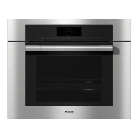
Miele DGC 6 Series Manual

TECHNICAL INFORMATION
DGC 6xxx Combi-Steam Ovens
© 2018 Miele USA

Technical Information
2
DGC 6xxx
Table of Contents
AWarning and Safety Instructions...............................................................9
BModification History ...................................................................................9
CTechnical Data ............................................................................................9
DLayout of Electrical Components ............................................................10
1Optical Interface.....................................................................................................10
2Electrical Components ...........................................................................................11
010Casing........................................................................................................15
2 Function .................................................................................................................16
2.1Door Contact Switch (S24).................................................................................16
3 Fault Repair............................................................................................................16
3.1CleanSteel Surface Scratched............................................................................16
4 Service ...................................................................................................................16
4.1 Removal from a Housing Unit.............................................................................16
4.2 Lid Removal........................................................................................................17
4.3 Right Side Panel Removal..................................................................................17
4.4Rear/Left Side Panel Removal ...........................................................................18
4.5Door Contact Switch (S24) Removal..................................................................20
4.6Cable Duct Removal...........................................................................................20
4.7Hinge Replacement............................................................................................22
020Door ...........................................................................................................23
4 Service ...................................................................................................................24
4.1Door Removal.....................................................................................................24
4.2 Door Disassembly...............................................................................................24
4.3 Door Handle Removal ........................................................................................26
4.4 Door Assembly ...................................................................................................26
4.5Door Installation..................................................................................................26
030Cavity .........................................................................................................27
1 Technical Data .......................................................................................................28
2 Function .................................................................................................................28
2.1 Heat-Flow Temperature Sensor (2R30-10) ........................................................28
3 Fault Repair............................................................................................................28
3.1 Cavity Surface Scratched...................................................................................28
3.2Noisy Operation..................................................................................................29
3.3Rust on Top Heat/Broil Element .........................................................................29
3.4Convection Fan Too Loud ..................................................................................29
4 Service ...................................................................................................................29
4.1 Convection Element (R14) Removal...................................................................29
4.2 Top Heat/Broil Element (R13/R15) Removal......................................................31
4.3 Bottom Heater Element (R12) Removal .............................................................32
4.4 Bottom Heater Element Temperature Sensor (R30/22) Removal.......................35

Technical Information
3
DGC 6xxx
4.5 Oven Light (1H3-2, 2H3-2) Removal ..................................................................35
4.6 Convection Heater Temperature Limiter (3F1) Removal....................................36
4.7Bottom Heat Temperature Limiter (2F1) Removal..............................................37
4.8 Cooling-Air Temperature Sensor (R30-34) Removal..........................................38
4.9 Heat-Flow Temperature Sensor (2R30-10) Replacement ..................................39
4.10 Roast Probe Socket (X5-8) Removal (Model-Dependent)..................................41
4.11 Roast Probe Antenna (W17) Removal (Model-Dependent)................................42
035Steam Generator, Convection Fan ..........................................................43
1 Technical Data .......................................................................................................44
2 Function .................................................................................................................44
2.1 Cavity Temperature Sensor (1R30-10)...............................................................44
2.2 Steam Generator (R25)......................................................................................45
2.3 Pinch/Drain Valve (M29).....................................................................................45
2.4 Drain Pump.........................................................................................................46
2.5 Flap Control to Reduce Steam and Regulate Moisture.......................................46
2.5.1 Flap Control......................................................................................................46
2.5.2 Air Flap Motor...................................................................................................47
2.5.3 Steam Reduction..............................................................................................47
2.5.4 Air Humidity......................................................................................................47
2.5.5Heat-Flow Sensor (WFS).................................................................................48
3 Fault Repair............................................................................................................48
3.1Knocking Noises.................................................................................................48
3.2Residual Water in Cavity ....................................................................................49
3.3Hose Kinked .......................................................................................................49
3.4Condensate/Drain Hose Cannot Be Connected .................................................50
4 Service ...................................................................................................................51
4.1Air Flap Motor (M28) Removal............................................................................51
4.2 Cavity Temperature Sensor (1R30-10) Removal................................................51
4.3 Drain Pump (M8) Removal .................................................................................52
4.4Steam Generator (R25) Removal.......................................................................52
4.5Convection Fan (M2-2) Removal........................................................................54
4.6 Pinch/Drain Valve (M29) Removal......................................................................55
4.7 Terminal Block Removal.....................................................................................56
040 Water Container, Drive .............................................................................58
1 Technical Data .......................................................................................................59
2 Function .................................................................................................................59
2.1Fascia Panel.......................................................................................................59
2.2Water Tank.........................................................................................................60
2.2.1Water Tank.......................................................................................................60
2.2.2Water-Tank Filling............................................................................................60
3 Fault Repair............................................................................................................60
3.1Fascia Panel Does Not Open.............................................................................60
3.2Fascia Panel Does Not Open or Close Correctly................................................60
3.3Fascia Panel Slips Down (Water Tank Can Be Removed).................................61
3.4Water Drips Out of the Drawer............................................................................61
3.5Fascia Panel No Longer Closes Automatically...................................................61
3.6Powdery Residue behind Fascia Panel..............................................................61
3.7Fascia Panel Is Crooked.....................................................................................62

Technical Information
4
DGC 6xxx
3.8Float Stuck in Water Tank ..................................................................................62
3.9Fascia Panel Does Not Respond When Sensor Is Pressed...............................62
3.10Hoses That Are Not Food-Safe Are Being Used.................................................63
3.11Lift Panel Not Holding.........................................................................................63
3.12 Guide Rail End Stoppers Difficult to Install.........................................................64
3.13 Fascia Panel Installed at an Angle......................................................................64
3.14 “Remove Roast Probe”.......................................................................................64
3.15 Float Fallen in Water Container..........................................................................65
4 Service ...................................................................................................................65
4.1Lift Motor (M19) Removal...................................................................................65
4.2 Drive Assembly Removal....................................................................................65
4.3Water Container Removal ..................................................................................66
045Air Duct, Power Electronic.......................................................................68
1 Technical Data .......................................................................................................69
2 Function .................................................................................................................69
2.1Feed Pump.........................................................................................................69
2.2Water Intake .......................................................................................................69
2.3Steam Reduction................................................................................................69
2.4Fan Run-On........................................................................................................70
2.5Steam Cooling/Combi Cooking...........................................................................70
2.5.1Steam Cooking 212°F......................................................................................70
2.5.2Steam Cooking below 212°F............................................................................71
2.5.3Combi Cooking.................................................................................................71
2.5.4Combination Cooking with Convection Plus....................................................71
2.5.5Combination Cooking with Browning/Bake......................................................71
2.5.6Combination Cooking with Broil.......................................................................72
2.6Care Programs ...................................................................................................72
2.6.1Rinsing .............................................................................................................72
2.6.2Soak.................................................................................................................72
2.6.3Drying...............................................................................................................72
2.6.4Descaling..........................................................................................................73
2.6.4.1Descaling.................................................................................................... 73
2.6.4.2Descaling Cycle.......................................................................................... 73
2.7Machine Response after a Power Failure...........................................................73
2.8 Wireless Roast Probe.........................................................................................73
2.8.1Components.....................................................................................................73
2.8.2Description of “Wireless Roast Probe” System................................................74
2.8.3Frequency Transmission/Reception in the “Wireless Roast Probe” System...75
2.8.4Use of the Wireless Roast Probe Thermometer..............................................76
2.8.5Measuring the Core Temperature Using Conventional Methods.....................77
3 Fault Repair............................................................................................................78
3.1Unsatisfactory Cooking Results, High Water Consumption................................78
3.2Programmed Time Changes to a Different Time ................................................78
3.3Relay Clicks Once per Second...........................................................................78
3.4No Steam after Bake Function............................................................................79
3.5Wireless Roast Probe Malfunctioning.................................................................79
4 Service ...................................................................................................................80
4.1Cooling-Fan (M2-1) Removal .............................................................................80

Technical Information
5
DGC 6xxx
4.2Heat-Flow Fan (2M2-1) Removal........................................................................81
4.3Feed Pump (M7) Removal..................................................................................82
4.4Fascia Panel Position Switch (S60) Removal.....................................................83
4.5Water Container Switch (B3-17, B3-18, B3-19) Removal...................................83
4.6Drain Pump Reed Switch (B1-2) Removal..........................................................84
4.7Lighting Electronic (N1/10) Removal ..................................................................84
4.8 Power Electronic (N1-1) Removal.......................................................................85
4.9Inlet Valve Removal............................................................................................86
4.10Air Duct Removal................................................................................................87
4.11 Roast Probe Electronic (N1-6) Removal.............................................................89
4.12Wireless Roast Probe Test.................................................................................90
060 Control Panel ............................................................................................92
2 Function .................................................................................................................92
2.1Optical Interface..................................................................................................92
2.2 M-Touch Display (Model-Dependent).................................................................92
2.3Loudspeaker.......................................................................................................93
2.4Operating Modes................................................................................................94
2.4.1Heater-Element Configurations........................................................................94
2.4.2Overview ..........................................................................................................95
3 Fault Repair............................................................................................................96
3.1 Fault Code F05 - Oven Pt1000 Temperature Sensor Short- Circuited ...............96
3.2Fault Code F06 - Oven Pt1000 Temperature Sensor Open- Circuited...............96
3.3 Fault Code F07...................................................................................................97
3.4 Fault Code F10 - Steam Generator Water Intake Fault......................................97
3.5Fault Code F11 - Steam Generator Drainage Fault............................................99
3.6Fault Code F20 – Heating Fault........................................................................100
3.7Fault Code F44 - Control Electronic/Power Electronic Interface Fault.............100
3.8Fault Code F54 – Roast Probe Short-Circuited ................................................100
3.9Fault Code F55 - Safety Cut-Out......................................................................100
3.10Fault Code F60 - Power Electronic Temperature Limit Exceeded....................101
3.11Fault Code F74 – Drain Valve Fault..................................................................101
3.12 Fault Code F94 - Plumbed-Water Connection Water Intake Fault....................101
3.13Fault Code F190 - Plumbed-Water Connection Valve Defective......................101
3.14Fault Code F191 - Heat-Flow Pt1000 Temperature Sensor Short- Circuited....101
3.15Fault Code F192 - Heat-Flow Pt1000 Temperature Sensor Open- Circuited ...102
3.16Fault Code F193 - Bottom Heat Pt1000 Temperature Sensor Short- Circuited 102
3.17Fault Code F194 - Bottom Heat Pt1000 Temperature Sensor Open- Circuited 102
3.18Fault Code F195 – Roast Probe Electronic Communication Fault....................102
3.19Fault Code F196 - Pump Sump Fault...............................................................103
3.20Fault Code F197 – Cooling-Air Pt1000 Short Circuit ........................................104
3.21Fault Code F198 – Cooling-Air Pt1000 Open Circuit........................................104
3.22Fault Code F235 – Control/Power Electronic Communication Fault.................105
3.23Fault Code F241 - Touchpad Communication Fault.........................................105
3.24 Fault Code F242 - Touchscreen Communication Fault ....................................105
3.25 Update Was Not Successful.............................................................................105
3.26Delay Start Cannot Be Selected.......................................................................106
3.27End Time Not Displayed...................................................................................106
3.28Appliance Must Be Descaled Frequently..........................................................106

Technical Information
6
DGC 6xxx
3.29Diagnostic Support Cannot Establish a Connection .........................................106
3.30Descaling Display.............................................................................................107
3.31Fascia Panel Does Not Respond to Sensor Touch...........................................107
4 Service .................................................................................................................108
4.1 Settings Menu...................................................................................................108
4.2Programming Mode..........................................................................................112
4.3Service Mode....................................................................................................114
4.4Fascia Panel/Control Electronic Assembly Removal........................................116
4.5 Loudspeaker Removal......................................................................................117
070Technical Service Bulletins ...................................................................119
1DGC6XXX Drain Faults Out-of-the-Box...............................................................119
2 DGC 6000 XXL Model – Large Cavity..................................................................120
3Gen6 Electronics for M-Touch Models.................................................................120
List of Figures
Figure D-1: Optical Interface for Diagnostic Support and Program Updating.................10
Figure D-2: DGC 6500/6600 Top Components...............................................................11
Figure D-3: DGC 6500/6600 Cavity and Heating Components ......................................12
Figure D-4: DGC 670x/680x Top Components...............................................................13
Figure D-5: DGC 670x/680x Cavity and Heating Components.......................................14
Figure 010-1: Removing the Appliance from a Housing Unit..........................................16
Figure 010-2: Lid Removal..............................................................................................17
Figure 010-3: Right Side Panel Removal........................................................................18
Figure 010-4: Rear/Left Side Panel Removal .................................................................19
Figure 010-5: Spacer Bar on Rear Panel........................................................................20
Figure 010-6: Door Switch Removal...............................................................................20
Figure 010-7: Cable Duct Screws...................................................................................21
Figure 010-8: Hinge Screws (Left Side Shown)..............................................................22
Figure 020-1: Hinge Brackets .........................................................................................24
Figure 020-2: Door Removal...........................................................................................24
Figure 020-3: Corner Bracket..........................................................................................25
Figure 020-4: Holding Strip and Seal Removal...............................................................25
Figure 020-5: Inner Panel Removal................................................................................25
Figure 020-6: Middle Panel Removal..............................................................................26
Figure 020-7: Door Handle Screws.................................................................................26
Figure 030-1: Inner Rear Panel Retaining Nuts..............................................................30
Figure 030-2: Convection Heater Element......................................................................30
Figure 030-3: Convection Element Connections and Retaining Nuts.............................31
Figure 030-4: Top Heat/Broil Element Mounting Bracket Screws...................................31
Figure 030-5: Top Heat/Broil Element.............................................................................32
Figure 030-6: Base Plate Screws....................................................................................33
Figure 030-7: Bottom Heater Element Retaining Bracket and Temperature Sensor......34
Figure 030-8: Bottom Heater Element Retaining Screw.................................................34

Technical Information
7
DGC 6xxx
Figure 030-9: Service Panel Screws...............................................................................35
Figure 030-10: Lighting Assembly Nuts..........................................................................36
Figure 030-11: Convection Heater Temperature Limiter.................................................37
Figure 030-12: Bottom Heat Temperature Limiter ..........................................................38
Figure 030-13: Cooling-Air Temperature Sensor, Heat-Flow Fan Housing and Hose....38
Figure 030-14: Heat-Flow Fan Housing Screws.............................................................39
Figure 030-15: Heat-Flow Temperature Sensor Housing...............................................40
Figure 030-16: Heat-Flow Temperature Sensor Installation...........................................41
Figure 030-17: Temperature Sensor and Seal................................................................41
Figure 030-18: Roast Probe Socket................................................................................42
Figure 035-1: Pinch/Drain Valve.....................................................................................45
Figure 035-2: Drain Pump...............................................................................................46
Figure 035-3: Old Hose Positioning................................................................................50
Figure 035-4: New Hose Positioning...............................................................................50
Figure 035-5: Air Flap Motor...........................................................................................51
Figure 035-6: Cavity Temperature Sensor Screws.........................................................52
Figure 035-7: Drain Pump Removal................................................................................52
Figure 035-8: Steam Generator/Mounting Bracket Assembly (Right Side Shown).........53
Figure 035-9: Steam Generator/Mounting Bracket Assembly, Upside Down.................54
Figure 035-10: Installing the Steam Generator at at Slight Angle...................................54
Figure 035-11: Inner Rear Panel Screws........................................................................55
Figure 035-12: Convection Fan Screws..........................................................................55
Figure 035-13: Drain Valve Removal..............................................................................56
Figure 035-14: Terminal Block........................................................................................57
Figure 040-1: Leaf Springs on Telescopic Rails .............................................................64
Figure 040-2: Lift Motor Screws......................................................................................65
Figure 040-3: Cog Wheel Setting....................................................................................66
Figure 040-4: Water Container Removal ........................................................................66
Figure 040-5: Water Container Spring............................................................................67
Figure 045-1: Wireless Roast Probe System..................................................................74
Figure 045-2: Wireless Roast Probe...............................................................................74
Figure 045-3: Inserting the Wireless Roast Probe..........................................................76
Figure 045-4: Distributor behind Cooling Fan.................................................................80
Figure 045-5: Cooling-Fan Screws .................................................................................81
Figure 045-6: Cooling Fan and Mounting Bracket ..........................................................81
Figure 045-7: Heat-Flow Fan Housing Screws...............................................................82
Figure 045-8: Heat-Flow Fan Orientation (Top View).....................................................82
Figure 045-9: Feed Pump...............................................................................................83
Figure 045-10: Position Switch Screws...........................................................................83
Figure 045-11: Water Container Switches......................................................................84
Figure 045-12: Lighting Electronic ..................................................................................84
Figure 045-13: Bracket in Front of Lighting Electronic....................................................85
Figure 045-14: Power Electronic.....................................................................................85
Figure 045-15: Inlet Valves.............................................................................................86
Figure 045-16: Inlet Valve Mounting Bracket..................................................................87
Figure 045-17: Cooling-Fan Temperature Limiter...........................................................87
Figure 045-18: Electronics Bracket Screws....................................................................88

Technical Information
8
DGC 6xxx
Figure 045-19: Screws Securing Distributors, Position Switch Mounting Bracket and Air
Duct.................................................................................................................................89
Figure 045-20: Roast Probe Electronic...........................................................................90
Figure 045-21: Wireless Roast Probe Test Setup...........................................................90
Figure 060-1: M-Touch Display.......................................................................................92
Figure 060-2: Rapid Heat-Up (R13 and R15 Alternately) ...............................................94
Figure 060-3: Convection................................................................................................94
Figure 060-4: Surround...................................................................................................95
Figure 060-5: Bake..........................................................................................................95
Figure 060-6: Browning...................................................................................................95
Figure 060-7: Convection Broil, Broil ..............................................................................95
Figure 060-8: Eco Broil ...................................................................................................95
Figure 060-9: Rotating the Drain Filter..........................................................................103
Figure 060-10: Fascia Panel Cover ..............................................................................117
Figure 060-11: Fascia Panel/Control Electronic Assembly...........................................117
List of Tables
Table C-1: Appliance Information....................................................................................10
Table 030-1: Heater Element Data .................................................................................28
Table 030-2: Oven Light Data.........................................................................................28
Table 030-3: Heat-Flow Temperature Sensor Resistance Chart....................................28
Table 035-1: Air Flap Motor Data....................................................................................44
Table 035-2: Cavity Temperature Sensor Data ..............................................................44
Table 035-3: Steam Generator Heater Data...................................................................44
Table 035-4: Steam Generator Temperature Regulator Data.........................................44
Table 035-5: Convection Fan Data.................................................................................44
Table 035-6: Drain Pump Data .......................................................................................44
Table 040-1: Lift Motor Data ...........................................................................................59
Table 045-1: Cooling-Fan Data.......................................................................................69
Table 045-2: Heat-Flow Fan Data...................................................................................69
Table 045-3: Feed Pump Data........................................................................................69
Table 045-4: Inlet Valve Data..........................................................................................69
Table 045-5: Fan Run-On Data.......................................................................................70
Table 060-1: Melodies for Appliances with Loudspeaker................................................94
Table 060-2: Operating-Mode Overview.........................................................................96
Table 060-3: Descaling Counter versus Water Hardness.............................................107
Table 060-4: Settings Menu..........................................................................................112
Table 060-5: Programming Functions...........................................................................113
Table 060-6: Service Mode Functions ..........................................................................116

Technical Information
9
DGC 6xxx
A Warning and Safety Instructions
Service may only be carried out by qualified electricians and in keeping
with the appropriate safety regulations.
All applicable guidelines, accident prevention rules and laws must be
observed.
Before service or repair work can be started, all cables carrying power
must be safely disconnected.
Even when the appliance is disconnected from power, elements may
carry voltage.
A general visual check must be performed at all times.
A touch current measurement must be conducted on all conductive parts
that are not connected to ground.
Wear protective gloves and use the edge protection (mat. no. 5057680) to
prevent cuts by sharp edges.
B Modification History
When? Who? What?
3/7/2018 Jessica Naples Tech service bulletin added
7/11/2017 Jessica Naples Minor changes throughout
10/19/2016 Jessica Naples Tech service bulletin added
3/22/2016 Jessica Naples Compilation for Website
C Technical Data
Model numbe
r
DGC 6500/6600 DGC 6700/6800 DGC 6705/6805
Oven type Single Single Single
Installation type Built-in Built-in Built-in
Door hinge location Bottom Bottom Bottom
Water supply Tank Tank Plumbed
Cavity capacity 1.4 cu.ft. 1.4 cu.ft. 1.4 cu. ft.
Niche dimensions
1
Height 17.6” - 17.8” 17.6” - 17.8” 17.6” - 17.8”
Width 22.0” - 22.4” 22.0” - 22.4” 22.0” - 22.4”
Depth 21.9” 21.9” 21.9”
Cavity dimensions
Height 9.5” 9.5” 9.5”
Width 13.2” 13.2” 13.2”
Depth 17.4” 17.4” 17.4”
Depth with door open 35.0” 35.0” 35.0”
Shipping weight 65 lbs 65 lbs 65 lbs

Technical Information
10
DGC 6xxx
Model numbe
r
DGC 6500/6600 DGC 6700/6800 DGC 6705/6805
Electrical connection (USA)
Voltage 240VAC 240VAC 240VAC
Output 3700W 3700W 3700W
Frequency 60Hz 60Hz 60Hz
Fuse 20A 20A 20A
Controls SensorTronic MTouch MTouch
Table C-1: Appliance Information
1When installing the appliance in a cabinet, make sure that the cabinet and the wall can
support the weight of the appliance.
D Layout of Electrical Components
1 Optical Interface
Figure D-1: Optical Interface for Diagnostic Support and Program Updating

Technical Information
11
DGC 6xxx
2 Electrical Components
Figure D-2: DGC 6500/6600 Top Components
1 (B3-18) Water tank sensor
2 (B1-2) Overflow switch (actually located next to the drain pump, not by the
electronic as the illustration indicates)
3 (B3-19) Condensate tank sensor
4 (S60) Lift panel position switch
5 (N1-1) Power electronic
6 (1F1) Fan temperature limiter (158°F)
7 (M2-1) Cooling fan
8 (N1-6) Roast probe electronic (with wire connection)
9 (M7) Feed pump
10 (M19) Lift motor
11 (B3-17) Water tank present sensor

Technical Information
12
DGC 6xxx
Figure D-3: DGC 6500/6600 Cavity and Heating Components
1 (S24) Door contact switch
2 (M8) Drain pump
3 (1H3-2) Cavity light
4 Roast probe socket cover
5 (N1-2) Control electronic
6 (M29) Pinch/drain valve
7 (1R25, 2R25, 3R25) Steam generator heater elements
8 (X7) Distributor
9 (1F1-5) Steam generator temperature monitor
10 (2F1-5) Steam generator temperature monitor
11 (R15) Broil element
12 (2M2-1) Heat-flow fan
13 (2R30-10) Heat-flow temperature sensor (Pt1000)
14 (1R30-10) Oven Pt1000 temperature sensor
15 (R30-34) Cool-air Pt1000 temperature sensor
16 (R13) Top heater element
17 (X3-1) Terminal block
18 (Z2) Interference suppression capacitor
19 (3F1) Convection temperature limiter
20 (M2-2) Convection fan
21 (M28) Air flap motor
22 (R14) Convection heater element
23 (2F1) Bottom heat temperature limiter
24 (R12) Bottom heater element
25 (R30/22) Bottom heat temperature sensor

Technical Information
13
DGC 6xxx
Figure D-4: DGC 670x/680x Top Components
1 (B3-18) Water tank sensor
2 (B1-2) Overflow switch
3 (B3-19) Condensate tank sensor
4 (N1-10) Lighting electronic
5 (S60) Lift panel position switch
6 (N1-1) Power electronic
7 (1F1) Fan temperature limiter (158°F)
8 (1M2-1) Cooling fan
9 (1Y63, 2Y63) Inlet valves (DGC 6x05 only)
10 (N1-6) Roast probe electronic
11 (M7) Feed pump
12 (M19) Lift motor
13 (B3-17) Fill-level sensor

Technical Information
14
DGC 6xxx
Figure D-5: DGC 670x/680x Cavity and Heating Components
1 (S24) Door contact switch
2 (M8) Drain pump
3 (1H3-2, 2H3-2) Oven cavity lighting
4 (N1-2) EPB/EPZ electronic
5 (M29) Drain valve
6 (1R25, 2R25, 3R25) Steam generator heater elements
7 (1X7) Distributor
8 (X10-1) RemoteVision interface
9 (1F1-5) Steam generator temperature limiter
10 (2F1-5) Steam generator temperature limiter
11 (W17) Roast probe antenna
12 (2M2-1) Heat-flow fan
13 (2R30-10) Heat-flow temperature sensor (Pt 1000)
14 (1R30-10) Oven cavity temperature sensor (Pt 1000)
15 (R15) Broil element
16 (R13) Top heater element
17 (X3-1) Terminal block
18 (Z2) Interference suppression capacitor
19 (3F1) Convection temperature limiter
20 (M2-2) Convection fan
21 (M28) Air flap
22 (R14) Convection heater element
23 (2F1) Bottom heat temperature limiter
24 (R12) Bottom heater element
25 (R30-22) Bottom heat temperature sensor

Technical Information
15
DGC 6xxx
010 Casing

Technical Information
16
DGC 6xxx
2 Function
2.1 Door Contact Switch (S24)
If the door is opened during a cooking cycle, the door contact switch provides
a signal to the electronic and the steam generator heater elements (1R25,
2R25, 3R25) are switched off.
3 Fault Repair
3.1 CleanSteel Surface Scratched
Cause:
A cleaner unsuitable for use with CleanSteel was used.
Remedy:
Do not clean the cavity with abrasive cleaning agents; see the operating
instructions.
4 Service
4.1 Removal from a Housing Unit
1. Remove all accessories from the cavity.
2. Remove the retaining screws; see Figure 010-1, Item 1.
3. Remove the appliance.
4. Disconnect the power connection.
Figure 010-1: Removing the Appliance from a Housing Unit

Technical Information
17
DGC 6xxx
4.2 Lid Removal
1. Remove the appliance from its housing unit; see Section 010-4.1.
2. Disconnect the appliance from the power supply.
3. Pull out the fascia panel.
4. Open the door.
5. If applicable, remove the two retaining nuts (5.5mm) from the underside
of the lid, next to the water and condensate tanks.
6. Remove the eight T20 screws; see Figure 010-2, Item 1.
7. Remove the lid.
Figure 010-2: Lid Removal
4.3 Right Side Panel Removal
1. Remove the appliance from its housing unit; see Section 010-4.1.
2. Disconnect the appliance from the power supply.
3. Remove the lid; see Section 010-4.2.
4. Remove the retaining screws; see Figure 010-3, Item 1.
5. Remove the right side panel.

Technical Information
18
DGC 6xxx
Figure 010-3: Right Side Panel Removal
4.4 Rear/Left Side Panel Removal
Note:
The left side panel is combined with the rear panel.
1. Remove the appliance from its housing unit; see Section 010-4.1.
2. Disconnect the appliance from the power supply.
3. Remove the lid; see Section 010-4.2.
4. Remove the five T20 screws securing the left side panel, as well as the
four T20 screws securing the rear panel; see Figure 010-4, Item 1.
5. Remove the rear/left side panel.

Technical Information
19
DGC 6xxx
Figure 010-4: Rear/Left Side Panel Removal
Note:
Some models have a spacer bar attached to the rear panel (see Figure 010-
5). For these models, remove the two T20 screws securing the spacer bar,
take the spacer bar off, and then remove the two T20 screws securing the
bottom of the rear panel.

Technical Information
20
DGC 6xxx
Figure 010-5: Spacer Bar on Rear Panel
4.5 Door Contact Switch (S24) Removal
1. Remove the door; refer to Section 020-4.1.
2. Remove the appliance from its housing unit; see Section 010-4.1.
3. Disconnect the appliance from the power supply.
4. Remove the lid; see Section 010-4.2.
5. Remove the rear/left side panel; refer to Section 010-4.4.
6. Remove the two T20 screws securing the hinge on the left side.
7. Disconnect the switch connections.
8. Lift the hinge up.
9. Unclip the switch assembly at the bottom (Figure 010-6, Item 1) and slide
it out of the hinge assembly.
Figure 010-6: Door Switch Removal
4.6 Cable Duct Removal
1. Remove the appliance from its housing unit; see Section 010-4.1.
This manual suits for next models
6
Table of contents
Other Miele Oven manuals

Miele
Miele H6160B User manual

Miele
Miele H6260BP User manual

Miele
Miele H 373-2 B User manual

Miele
Miele H 4450 Specification sheet

Miele
Miele H4881B User manual

Miele
Miele H 5051 B User manual

Miele
Miele H 7464 BP User manual

Miele
Miele DG 6100 User manual

Miele
Miele DGC 7440 X User manual

Miele
Miele H 394 User manual

Miele
Miele H4742BP User manual

Miele
Miele H 2261 B User manual

Miele
Miele H 267 B User manual

Miele
Miele H6860BP User manual

Miele
Miele H 7464 BP User manual

Miele
Miele H 5740 BP User manual

Miele
Miele H 378-1 B2 User manual

Miele
Miele H 6880-2 BP User manual

Miele
Miele H6680BPOB User manual

Miele
Miele DGC 7440 User manual