Mielta Fantom FLS-3304-11-10 Manual instruction

FUEL LEVEL SENSOR
Fantom
FLS –3304-11-10
FLS –3304-11-15
FLS –3304-11-20
FLS –3304-11-25
FLS –3304-11-30
Setup and operation Manual
Firmware version 1.3.36
Configuration program version 3.6
Document edition from 20.01.2022
Tambov 2022

MIELTA Fantom
2
CONTENTS
1. Description................................................................................................... 3
2. Specification................................................................................................. 3
2.1 Power supply........................................................................................ 4
2.2 Measurer part ......................................................................................4
2.3 Radio communication........................................................................... 4
2.4 Active protection.................................................................................. 5
3Installation and connection..........................................................................5
4Sensor setup................................................................................................. 8
4.1 Calibration............................................................................................ 9
4.2 Anti-aliasing.......................................................................................... 9
4.3 Measurement and transmission......................................................... 10
4.4 Data transmission format and power................................................. 11
5. Transportation and storage........................................................................ 11
6. Warranty condition .................................................................................... 11
7. Package Contents....................................................................................... 11

MIELTA Fantom
3
1. Description
Wireless Fuel level sensor (FLS) Fantom MIELTA is designed to measure the level
of light oil hydrocarbons (diesel, fuel, gasoline, kerosene and etc.) in various purposes
containers. Sensor can be installed both on stationary objects and on automobile and
railway transport.
Sensor uses the linear capacitor capacitance measuring method. The capacitance
value depends on sensor immersion level in the dielectric liquid.
The sensor is made in a strong plastic case with IP67 protection class, it has a steel
flange with holes for mounting. Sensor`s tube and electrode is made of stainless steel and
it has oil-resistant dielectric coating. Radio communication antenna is Bluetooth Low
Energy (BLE) and the battery is inbuilt.
2. Specification
CHART 1.
POWER SUPPLY
Battery Li-SOCL2
3.6 V, 2.7 А*h
MEASUREMENT PERIOD
from 1 to 10 sec
THE PERIOD OF SENDING DATA
from 1 to 10 sec
AVERAGING INTERVAL
from 1 to 60
RELATIVE MEASUREMENT ERROR
No more than 1%
DATA TRANSFER FORMAT
0 –Mielta
1 –analog №1
WIRELESS TRANSMITTER
Bluetooth Low Energy 5.0, 2.4 GHz
FREQUENCY RANGE
2400-2483,5 mHz
TRANSMITTER POWER
Adjustable, <11 dBm EIRP
TILT ANGLE MEASURER
Inbuilt accelerometer, +/- 1G
α°=arcsin(Z/127)
TEMPERATURE MEASURER
inbuilt, +/- 2°С
INBUILT MEMORY
4 Mb
WIRELESS SOFTWARE UPDATE AND
CONFIGURATION
YES
DEGREE OF PROTECTION
IP67
EXPLOSION PROTECTION MARKING
0ExiaIIBT6X
OPERATING TEMPERATURE
from - 40 to +85 °C
OPERATING PERIOD
7 years
THE LENGTH OF THE MEASURING PART
*990 (1490, 1990, 2490, 2990) mm
DIMENSIONS OF HOUSING
80х80х25 mm

MIELTA Fantom
4
DIMENSIONS OF SENSOR
80х80х1015 (1515, 2015, 2515, 3015)
mm
*When mounting sensors with a length of more than 990 mm on moving objects, additional fastening of the sensor tube is
required
Mielta hereby declares that the type of radio equipment the FANTOM fuel level
sensor complies with Directive 2014/53 / EU.
2.1 Power supply
FLS Fantom has a lithium-thionyl chloride battery, a voltage of 3.6 V and a nominal
capacity of 2.7 А*h., which is designed for the entire service life in accordance with the
manufacturer's recommendations for setting the frequency of measurement and sending data.
After a malfunction, the battery can be replaced in the Mielta production laboratory, for this
you need to contact the technical support service.
The sensor detects its position in real time and when it deviates from the vertical by an
angle of more than 60 degrees, the power saving mode will be activated. The FLS switches
off the measuring device and continues sending the last recorded value, while still being able
to connect and configure. Therefore, the sensor can be stored in the warehouse in a horizontal
position. In this case, the power consumption is reduced to 30% from the rated one. The
sensor operation is guaranteed in the battery voltage range from 3.0V to 3.6V.
2.2 Measurer part
FLS Fantom is equipped with a unique integrated measuring device that converts the
capacity of a linear sensor element into a digital value used in fuel level calculations. A
essentially different method of measuring capacitance from the competitors allows you to
make measurements with high resolution and stability.
It has been implemented a new algorithm for self-diagnosis in emergency. If the
measurement range specified during calibration is exceeded with error code, the sensor shows
the deviation amount. Analysis of the error value may indicate the cause of the fault: incorrect
calibration, changes in fuel quality, or water and dirt is in the fuel.
2.3 Radio communication
The sensor is equipped with a modern integrated Bluetooth 5.0 Low Energy radio
transmitter and a built-in high-performance antenna, which allows providing high-quality
radio communication with minimal power consumption.
The parameters measured by the sensor are transmitted in a BLE standard broadcast
packet (chart 2).

MIELTA Fantom
5
CHART 2.
Parameter
Valid values
Description
Level
from 0 to 10000
The value of the fuel level.
The range is configurable, by default 30 - 4095
2xххх
Error, level is below the minimum, where xxxx is value of the
level decrease as a percentage of the operating range
3xххх
Error, level is above the maximum, where xxxx is the value of
exceeding the level as a percentage of the operating range
40000
No Calibration (required a calibration)
Temperature
from -50 to
+100
Temperature of the housing FLS, °С
-127
Error, temperature below -50 °С
+127
Error, temperature above +100 °С
Battery voltage
from 10 to 40
Battery voltage in volts, multiplied by 10
0
Error, voltage is below 1.0 V
255
Error, voltage is above 4.0 V
Acceleration
along the
longitudinal axis
of the sensor
from -127 to
+127
The angle of inclination of the sensor relative to the horizontal
position is calculated by the formula α°=arcsin(Z/127).
The value of the parameter: 0 –horizontal position;
+127 –vertical position, housing is up;
-127 –vertical position, housing is down;
To monitor and change the sensor settings, its calibration and taring, you must use any
mobile device with Bluetooth version 4.2 or later, as well as the program-Configurator for
mobile devices Mielta Device Manager (Mielta DM) for the relevant operating system
(Android, iOS). The program is available for free in the Google Play and App Store.
2.4 Active protection
Fantom has a built-in sensor that can detect attempts to cover it with any conductive
material (metal) in order to destabilize or disrupt data transmission over the radio channel.
The sensor will analyze data, will store in memory and will transmit this data into the terminal
via a special Protocol.
Even if the user succeeded in blocking radio communication for some time, data on
the fact of sabotage will be transmitted immediately as soon as the connection is resumed.
3Installation and connection
The sensor is mounted at the top of the fuel tank and opposite to the lowest point of
the bottom of the tank. Preference is given to an layout that provides minimal overlaps of the
space around the sensor housing with metal structures and has open access to the surrounding
space. Around its axis, the sensor must be oriented in such a way that the priority direction of
the antenna radiation (Pic. 1) is directed as much as possible in the maximum opposite
direction to the metallic construction.

MIELTA Fantom
6
Picture 1. The installation dimensions of the FLS.
Picture 2. Sensor connecting dimension.
The surface for mounting the sensor must be horizontal and selected with regard to the
availability and ease of installation. The central hole has a Ø20 mm. diameter (Pic. 2). The
mounting holes diameter is chosen based on the material of the fuel tank and the attachment
method. It is used self-tapping screws to fix the sensor. When mounted on a metal tank, 4
holes with a diameter of 4-4.5 mm are drilled or screws with a drill are used. When mounted
in a plastic tank, 4 holes with a diameter of 3 mm are drilled and self-tapping screws without
a drill are used.
Priority direction of radiation of
the antenna

MIELTA Fantom
7
Mounting procedure:
1. Select a location for installation, clean it of contamination.
2. Mark the holes according to the template, drill and remove the sawdust.
3. Measure the depth of the fuel tank from the bottom to the mounting surface.
4. Measure the sensor length from the mounting flange 20 mm shorter than the
measured depth of the fuel tank.
5. Saw off the tube and the central electrode, deburr, insert the insulator into the end
of the measuring tube.
6. Calibrate the sensor FLS.
7. Clean and degrease the mounting surface of the fuel tank. Apply a sealant to the
surface, glue the rubber seal. Apply the sealant to the gasket and install the sensor.
8. Secure the sensor with screws.
9. Seal the mounting screws with a wire seal.
If necessary, to bypass obstacles in fuel tanks with complex shape, the measuring tube
of the sensor can be bent. Bending is performed using specialized pipe benders with a bend
radius of at least 250 mm. The bend angle should not exceed 15 degrees (Pic. 3).
Bending sensor tube procedure:
1. Calculate the location of the fold, mark it on
the sensor tube;
2. Place the sensor tube in the pipe bender with
the label in the middle;
3. Open the FLS connection in the mobile APP
Configurator and monitor the value Level
row;
4. Bend the tube until the required angle is
reached, preventing the closure of the central
electrode and tube.
5. If there is an electrical short circuit of the
central electrode and tube, it is necessary to
reduce the angle of the bend by applying force
to the folding position on the reverse side,
until the guaranteed isolation of the electrode
from the tube is achieved.
6. Saw the measuring tube to the required
length.
7. Calibrate, install and do taring the sensor.
If necessary, the sensor tube can be bent in
two or more places to give it a complex shape.
Please, note that the bent measuring tube loses its symmetry and linearity, which
directly affects the values of the sensor. A bent sensor without taring can have non-linear
Picture 3. Sensor tube bending.

MIELTA Fantom
8
distortions in the readings at different levels. During taring of the sensor, it is recommended
to do more number of measuring points (30-50 points per meter) to compensate nonlinearity.
4Sensor setup
To configure the sensor, use The Mielta Device Manager Configurator program, it is
available for free in the Google Play and App Store app stores. For full operation, you must
confirm all the permissions requested by the program.
After installing and running the program, the "Connection" tab will show a search for
BLE devices (Pic. 4). Swipe down activates the next search. Found a FLS Fantom device in
the list will have a name, it contains the prefix "MD" and last 4 digital serial number of the
sensor. When you select one sensor from the list, the parameters window will be open (Pic.5)
which will show all the data transmitted by the sensor in common mode with a specified
interval.
To configure the sensor, you must activate the two-way connection. In this mode, the
sensor will show an expanded list of parameters in real time (Pic. 6).
The value of fuel level is set to the value 2048, if there is no calibration parameters, a
calibration must be made.
There is a data reception indicator “Link” in the upper right corner of the window.
When the data packet comes from the sensor, the indicator flashes green every time. When
the sensor is in the “Connection” mode, the data transmits faster and the indicator lights up
constantly.
Picture 4. Search window.
Picture 5. Parameters window
Picture 6. Connecting

MIELTA Fantom
9
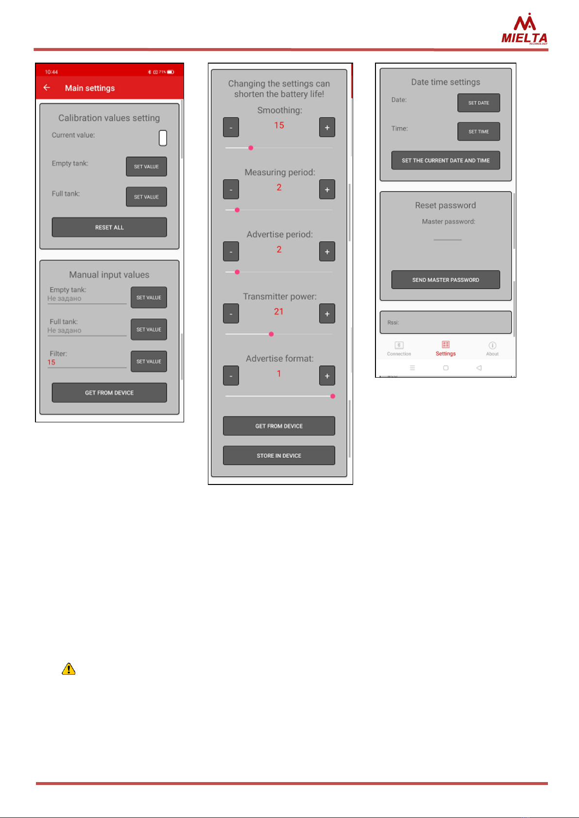
“Settings” tab shows list of settings (Pic. 7).
The Main settings include calibration of the fuel level sensor, parameters os the sensor
and settings of the date and time.
4.1 Calibration
The “empty tank” and “full tank” calibration values
set the measurement range in conventional units which
measures within the specified range of output values.
Calibration must be done after cutting the measuring tube
to the required depth and installing the insulator-plug.
First step is the "full tank" calibration. It must be
performed by dipping the sensor into the fuel tank till to
the level of the drain hole. After the current value from the
sensor is stabilized, you can write this value into
parameters. (Pic. 8).
The second step is the "empty tank" calibration. For
this, remove the FLS from the fuel and let the remaining
fuel flow out of the tube for 5 minutes. After stabilization,
you can write the value from the sensor for the empty tank
in the relevant parameter.
If you do first "empty tank" calibration,
without wetting the sensor (before “full tank”
calibration), it will cause the operating range to
be set incorrectly.
If necessary, the calibration values can be written manually in the relevant section of
the window (Pic. 8)
4.2 Anti-aliasing
The sensor has “anti-aliasing” parameter, to reduce fluctuations in the level value. This
parameter sets the number of recent measurements value and calculate the average value.
(Pic. 8). The parameter has a range of acceptable values from 1 to 60. The value 12 is set by
default. This parameter may have a value of more than 30 for some types of equipment or
tanks without partitions.
Picture 7. Settings list
MIELTA Fantom
10
4.3 Measurement and transmission
The values of the measurement period and the transmission period (advertising)
directly affect the speed of the sensor's response to changes in the level and its power
consumption. These parameters should be in the range from 1 to 10.
By default, the following values are set: the measurement period is 5 seconds, and the
transmission period is 2 seconds. These values are used in calculating the guaranteed period
of operation on a single battery.
Changing the parameters, the frequency of measurement and transmission to
less multiplies the consumption and reduces the life of the sensor. The
manufacturer does not guarantee the service life in case of changes of these
parameters.
Picture 8. Main settings
MIELTA Fantom
11
4.4 Data transmission format and power
The transmitter power parameter can be in the range from 0 to 49. The default value is
24. Increasing the power of the transmitter in some situations can improve the quality of
signal. However, the location of the FLS and receiving tracker and shielding metallic
constructions has a much bigger effect to the quality of the signal.
An increased transmission power also leads to increased power consumption.
FLS Fantom supports two formats:
Option 0 (by default) –format Mielta;
Option 1 - similar sensor from other manufacturers.
5. Transportation and storage
The fuel level sensor should be stored in warehouse conditions at a temperature of
20°C to + 50°C аnd a relative humidity of not more than 85°C. Contact with conductive dust,
water and technical liquids is eliminated. Sensor is transported in the original packing, by any
kind of transport.
6. Warranty condition
The manufacturer guarantees the operation of the fuel level sensor within 3 years from
the date of sale, in case that the consumer complies with the conditions and rules of
transportation, storage, installation and operation. The average service life is 7 years.
Warranty does not apply:
- for the sensors with mechanical damages and defects (cracks, chips, dents, traces of
impacts, thermal, electrical and chemical effects) caused by the fault of the consumer or third
parties due to violation of operating, storage or transportation conditions;
- for the sensors with traces of repair outside the manufacturer's service center;
- for the sensors which failed due to incorrect software update.
7. Package Contents
Name
Quantity
FLS Mielta Fantom (FLS-3304-11)
1
Mounting kit:
- gasket
- insulator-plug
- self tapping screw
- self-tapping screw for sealing
- seal
- wire for sealing
1
1
2
2
1
1
Passport
1
Packaging
1
MIELTATECH.COM
sales@mielta.ru
This manual suits for next models
4
Table of contents
Other Mielta Accessories manuals


