Mielta Katana Manual instruction

Fuel level sensor
«Katana»
Setup and Operation Manual
Hardware version 12
Software version 2.2.2
Configuration program version 2.1.0
Amended on 13.08.2021
Tambov 2022

Table of contents
1. Description 3
2. Specification 4
2.1 Power supply 4
2.2 Frequency output 5
2.3 RS485 interface 5
3 Installation and Connection 7
4 Configuartion of the sensor 11
4.1 Connection to the sensor 12
4.2 Calibration 13
4.3 Taring 14
4.4 Other settings 15
5. Transportation and storage 18
6. Warranty terms 18
7. Package contents 18
2

1. Description
Fuel Level Sensor (FLS) Katana MIELTA is designed to measure the level of light
petroleum hydrocarbons (diesel fuel, gasoline, kerosene, etc.) in containers for various
purposes. Sensor can be installed both on stationary objects, and on vehicles and railway
transport.
Sensor uses the linear capacitor capacitance measuring method. Capacitance value
depends on the level of dipping into the dielectric liquid.
The sensor is made in a durable plastic housing with IP68 protection, equipped with
a flexible cable and a sealed connector. The sensor mounts in a hole in a container (tank)
and has a flange for mounting with screws.
3

2. Specification
Table 1.
Supply voltage
8 – 55 V
Average power consumption
0,5 W
Measurement period
1 sec
Average interval
1-60 sec
Relative level measurement error over the entire
range
1%
Frequency output: maximum frequency range
30-2047 Hz
Frequency output discreteness
1 Hz
Frequency output pull-up to the power supply
3.3 В, 470 kOhm
Frequency output current limitation
0,1 А
RS485 baud
9600, 19200, 38400, 57600, 115200
baud, 8n1
Measurement part length
990 mm
Cable length
0,7 m
Mounting kit cable length
7 m
Operating temperature
-40..+80 °С
Housing Ingress Protection
IP68
Sensor dimensions
82 х 86 х 1015 mm
2.1 Power supply
FLS is designed to work in the on-board power with a nominal voltage of 12 or 24
volts, has a reverse-polarity protection, over-voltage protection and a self-repairing fuse. A
wide range of operating voltage allows the sensor to work stably even in abnormal situations
- when the voltage is low up to 8 V or raised above the norm up to 55 V.
If the supply voltage exceeds 55 V, a protective diode and a self-repairing fuse in the
FLS circuit is triggered, and the sensor power is turned off. After reducing the supply voltage
level to the operating (normal) range, the sensor restores its operability.
2.2 Frequency output
The sensor`s frequency output is designed to transmit the data in a discrete signal
form of variable frequency and a 50% duty cycle. The positive signal potential is provided by
a pull-up to the sensor supply via resistor. The negative potential is formed by a transistor,
operating in a common-emitter circuit. The frequency output maximum current is limited to
100 mA. When the maximum current limit is exceeded, the high-speed protection is
triggered and deactivates the output. When the current is reduced to an acceptable value,
the frequency output continues to function.
The lower value of the output frequency is 30 Hz. The upper value is set
programmatically in the range of 500-2048 Hz.
If an error occurs, the sensor sets the frequency corresponding to the error code (see
Table 2). The error is also duplicated over the digital protocol.
Table 2.
4

Freq., Hz
Error code
Error description
20
20
Level is less than the minimum at calibration
Max +50
5000
The level is higher than the maximum at
calibration
Max +100
6000
Exceeding the measurement limits, short circuit
of the measuring system
If it is necessary to match the frequency output to a voltage level lower than the
sensor supply voltage, it is necessary to turn-off the inbuilt pull-up and use an external
pull-up resistor. The nominal value of the resistor is selected in such a way that, when
short-circuited to ground, it provides a current in the range of 5-10 mA (for example, a
resistor from 1200 to 2400 ohms is needed for 12V).
When connecting the sensor to the data reading system (tracker), it is necessary to
combine potentials (connection of negative power wires).
2.3 RS485 interface
The digital interface RS485 is made according to the international standard ANSI
EIA/TIA-485-A. The data is transmitted using a protocol developed by MIELTA, which is
compatible with the LLC protocol for receiving fuel level data.
The digital interface is designed to receive telemetric data from the sensor, configure
parameters and update the firmware. It is used to connect to a monitoring system or a
personal computer (PC) using a USB-RS485 adapter. To work with a PC, a configurator
program is used, which implements all possible functions of the sensor.
The RS485 interface allows you to connect several sensors to one terminal port (Pic.
1, 2). All MIELTA satellite terminals support the connection of up to 8 any sensors or
peripherals on the RS485 bus.
Picture No 1. Type "star" connection scheme.
5
When connecting several sensors at a distance less than 20 m from a tracker, the
"star" scheme is recommended. This scheme does not require additional terminal
resistors..
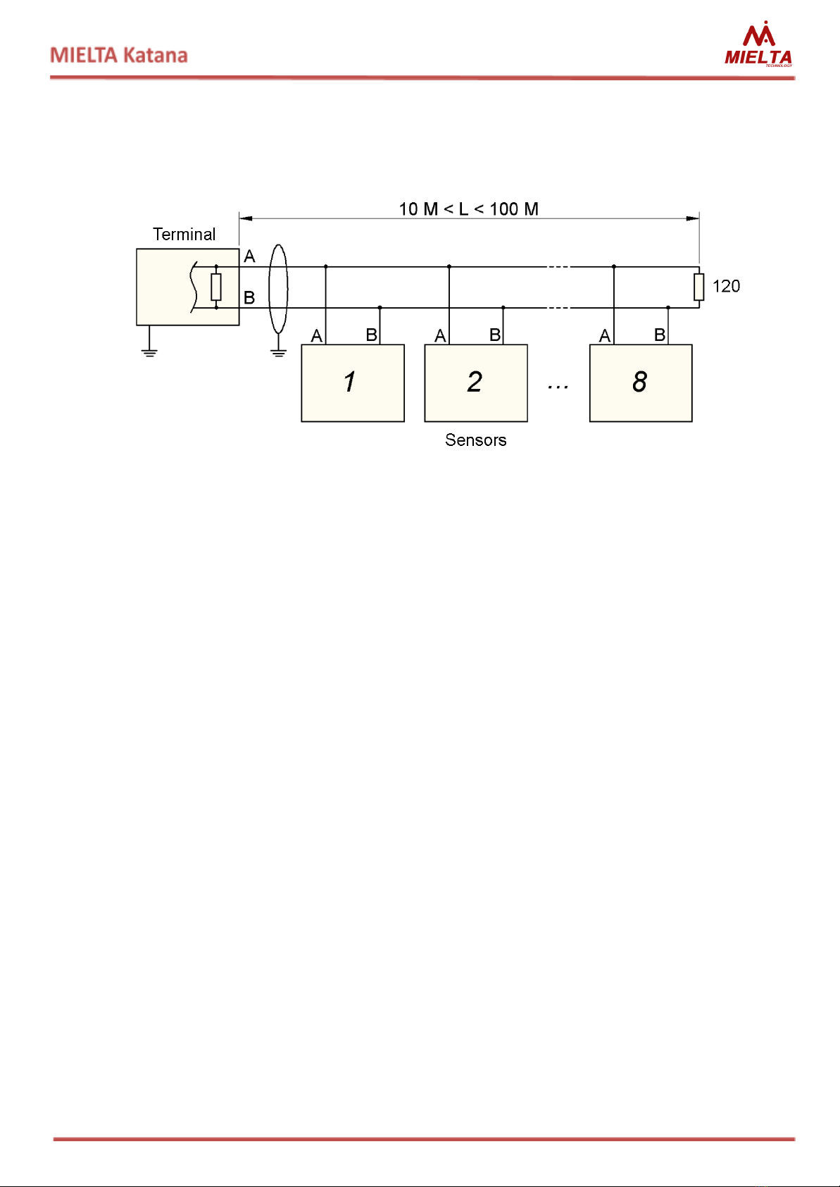
Picture No 2. Type "bus" connection scheme.
The "bus" scheme connection is used to connect several sensors at distances up to
100 m. In this case, an external termination resistor of 120 ohms 0.25 W is required, which is
connected at the location of the most remote sensor from the terminal.
If the length of the bus is more than 20 meters, it is recommended to use a shielded
twisted-pair. The cable shield is connected only from one side to the «-» terminal's contact
("-" supply). The connection of the cable shield to the sensor's «-» is not required. The
terminal and sensor power supplies must have a common «-» potential.
Before connecting several sensors to the common bus, it is necessary to configure
each of them individually. All devices on the bus are assigned a unique addresses.Then for
each sensor set the address, the transmission rate and the type of data requested (level,
output frequency or temperature) in tracker.
The digital value "level" is in the range 30 - 4095. Values of 20, 5000 and 6000 are
error codes in the sensor operation (Table 2). The digital value "frequency" is the frequency
formed at the sensor frequency output, the upper value of which is programmed (see
"Frequency output" section). The value "temperature" reflects the actual temperature in the
sensor housing.
3 Installation and Connection
The sensor is mounted at the top of the fuel tank and opposite to the lowest point of
the bottom of the tank. The surface for mounting the sensor must be horizontal and selected
with regard to the availability and ease of installation.
6

Picture No 3. Mounting dimensions of FLS.
The central hole has a Ø25 mm diameter (Pic. 3). The mounting holes diameter is
chosen based on the material of the fuel tank and the fixation method. Self-tapping screws
are used to fix the sensor. When the sensor is mounted on a metal tank, It is drilled 4 holes
with a diameter of 4-4.5 mm or It is used screws with a drill. When the sensor is installed in a
plastic tank, It is drilled 4 holes with a diameter of 3 mm and it is used self-tapping screws
without a drill.
7

Picture No 4.Dimension of FLS.
Installation procedures:
1. Select a location for installation, clean it of contamination.
2. Mark the holes according to the template, drill and remove the sawdust.
3. Measure the depth of the tank from the bottom to the mounting surface.
4. Measure the sensor length from the mounting flange 20 mm shorter than
the measured depth of the fuel tank.
5. Saw off the tube and the central electrode, clean off the burrs, put the remote
insulator into the end of the measuring tube.
6. Calibrate the sensor (section 4.2).
7. Clean and degrease the mounting surface of the fuel tank. Apply sealant to the
surface, glue a rubber gasket. Apply a sealant to the rubber gasket and install the
sensor.
8. Fixate the sensors with screws.
9. Connect the cable connector.
10. Seal the sensor mounting and connector.
If necessary, to avoid obstacles in tanks of complex shape, the measuring tube of the
sensor can be bent. Bending is performed by using specialized pipe bends with a bending
radius of at least 250 mm. The bend angle should not exceed 15 degrees. (Picture 5).
8

The operations sequence during bending:
1. Disconnect sensor from the power supply;
2. Calculate the location of the fold, mark it on
the sensor tube;
3. Place the sensor tube in the pipe bend with a
mark in the middle;
4. Connect the measuring device (multimeter)
in the continuity mode with probes to the
tube and the central electrode, respectively;
5. Bend the tube until the required angle is
reached, preventing the closure of the central
electrode and tube;
6. If there is an electrical shortage of the central
electrode and tube, it is necessary to reduce
the angle of the bend by applying force to the
folding position on the reverse side, until the
central electrode from the tube insulation
guaranteed;
7. Cut the pipe to the required length.
8. Calibrate, install and taring the sensor.
If necessary, the sensor tube can be
bent in two or more places to give it a complex
shape.
Please, note that the tube, after bending, loses its symmetry and linearity, which
directly affects the sensor readings. A sensor without taring can have non-linear distortions
in the readings at different levels. During sensor`s taring, it is recommended to do more
measurement points (30-50 points per meter) to compensate for nonlinearity.
Table 3.
№ Pin
Wire color
Purpose
1
Red
Plus power (“+”)
2
Black
Minus supply (“-“) (GROUND)
3
Yellow
RS485-A
4
Blue
RS485-B
5
White
Frequency output
6
-
-
9

Рисунок 6. Нумерация контактов в разъеме
жгута.
Рисунок 7. Нумерация контактов в
разъеме ДУТ.
●All electrical connections must be soldered or crimped. Seal the joints using a
heat-shrinkable adhesive tube.
4 Configuartion of the sensor
To configure the Sensor use the configurator program. Viewing Sensor information is
available without limitations, and to change the settings is required a password. By default,
the manufacturer sets the password «0000».
Picture 8. Main window of the configuration program
10

4.1 Connection to the sensor
Connection to the sensor is possible via the RS-485 interface with using a special
adapter. Before you start working with the sensor, you need to search for devices on the
RS-485 bus. To do this, click the "Sensor Select" button, which is located in the "General"
menu of the configuration program (Picture. 8).
In the window that opens, specify the serial port to which the RS-485 adapter is
connected, select the search mode (broadcast or by address range), and click the "Search"
button (Picture. 9). The search results will be displayed in the right part of the window in the
"Discovered sensors" block in the following format:
COM-port :RS-485 address : port speed
Picture 9. "Search and select sensor" window
For example, in the Picture 9, the program detected one sensor with address 3,
configured for a speed of 19200. To start working with the required sensor, click on the
corresponding line with the left mouse button. The program will connect to the sensor and
display its parameters in the main window.
4.2 Calibration
Before using the Sensor, it is necessary to calibrate it by the values "empty tank" and
"full tank". These values will match the sensor readings 0% and 100%, accordingly.
Sensor calibrating procedure:
1. Cut the sensor measuring tube at a distance from the mounting flange 20 mm
shorter than the depth of the fuel tank.
2. Connect the Sensor to the configuration program (section 4.1).
3. Sink the sensor tube into the fuel tank to the maximum depth (up to the drain
hole)
11

4. After stabilizing the readings in the program, perform calibration on a "full tank"
(Picture 10).
5. Remove the Sensor from the fuel tank, let the remaining fuel drain for 5
minutes.
6. After stabilizing the readings in the program, perform calibration on a "empty
tank” (Picture 10).
●Calibrate the sensor in the specified sequence. Calibration on the "empty tank"
value of a dry sensor (without filling the sensor tube into the fuel) causes incorrect
level readings. Fuel vapors in the tube significantly affect the sensor readings.
Picture 10. Calibration (Sensor is not calibrated)
The red color means that there is no calibration at the corresponding point. To calibrate the Sensor
at the required point, press the relevant "Calibrate" button. After the calibration, the line will change its
color to green. To calibrate the sensor again, press the “Calibrate” button again. To completely reset the
Sensor calibration (in two points), press the "Reset calibration" button.
4.3 Taring
Sensor taring is to create a table to link the sensor level readings to the actual volume
of fuel in the tank. Taring is done for each fuel tank individually and it is necessary to get
readings in liters with a certain accuracy and linearity. The more complex the shape of the
fuel tank, the more calibration points need to be made. Most often, 20-40 calibration points
are enough in practice.
The configuration program allows you to simplify the sensor taring process, using the
"Taring" program menu (Picture 11).
Before starting the taring process, select the required sensor parameter (level N or
frequency F) and set the taring step in liters. Fill the fuel tank with the required amount of
fuel, wait for the level to stabilize and press the "Add row" button - the program will
automatically fill the next line of the taring table in accordance with the selected parameters.
The Ready-made table can be saved to the Sensor memory (maximum 128 rows),exported
12

to an Excel file, printed out. Moreover, you can import a table from an Excel file. If a taring
table has already been recorded in the sensor, you can download it from the Sensor to the
configuration program using the "Read table" button (Picture 11).
Picture 11. Taring.
4.4 Other settings
Configuration program allows you to change the following Sensor settings.
●Sensor address on the RS-485 bus (valid values are 0...254);
●RS-485 bus speed (9600, 19200, 38400, 57600, 115200);
●Default Sensor data output mode operation:
⇨without automatic data output;
⇨automatic data output in binary form;
⇨automatic data output in symbolic form;
●Automatic data output interval (1..60 sec);
●Sensor data filtering interval (1..60 sec);
●The upper limit of the frequency output (500..2047 Hz);
●Turning on or off the frequency output pullup;
●User password for changing Sensor settings.
After changing the settings, click the "Write" button to save the new settings to the
sensor.
All changes made to the sensor settings are recorded in the configuration change log,
which is stored in the internal memory of the sensor. In addition, the sensor stores the total
13

operating time and the number of starts in the internal memory. To view the log of changing
settings, use the "Log" program menu (Picture 12).
Picture 12. Sensor settings change log.
To download a log from the Sensor, click the "Get log data" button. To save the log to
a text file, click the “Export to File” button.
The "Service" program menu contains the following functions:
●change the user password;
●reset the user password using the master password;
●sensor firmware update;
●sensor reset.
Picture 13. . "Service" program menu.
14

To change the user's password, click the "Change password" button, in the opened
window enter the current and new passwords and click "Change" (Picture.14).
Picture14. . Change user's password.
●If the user's password is lost, it is possible to reset the user's password.To get a
master password, contact your hardware vendor.
Picture 15. User password reset.
To update the Sensor firmware, click the "Firmware update" button in the "Service"
menu, select the firmware file and click the "Update" button (Picture 16). During the update
process, do not interrupt communication with the Sensor and do not turn off the Sensor
power.
Picture 16. Sensor firmware update.
15
To reboot the Sensor, click the "Reboot" button in the "Service" menu.
3. Transportation and storage
The fuel level sensor must be stored in a warehouse at a temperature from -20 ° C to
+50 ° C and a relative humidity of no more than 85 ° C. Water ingress and technical liquids
must be excluded.
The Sensor is transported in the original packing, by any kind of transport.
4. Warranty terms
The manufacturer guarantees the operation of the fuel level sensor within 3 years
from the date of sale, subject to the consumer's compliance with the conditions and rules of
transportation, storage, installation, and operation. The average service life is 10 years.
Warranty does not apply:
- for the sensors with mechanical damages and defects (cracks, chips, dents, traces of
impacts, thermal, electrical and chemical effects) caused by the fault of the consumer or
third parties due to violation of operating, storage or transportation conditions;
- for the sensors with traces of repair outside the manufacturer's service center;
-for the sensors with traces of electrical and/or other damages caused by
unacceptable changes in the parameters of the external electrical network or signals;
- for the sensors which failed due to incorrect software update.
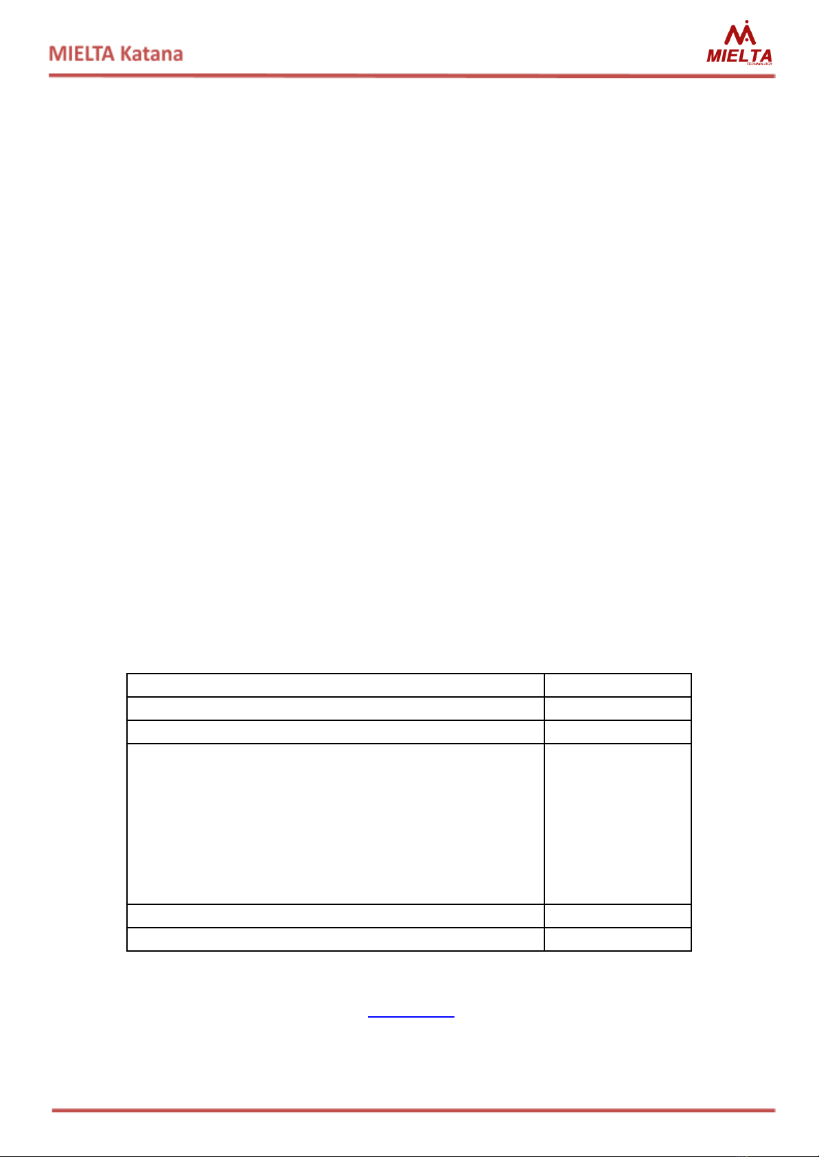
5. Package contents
Name
Quantity
FLS Mielta KATANA
1
Mounting cable
1
Mounting kit:
- Gasket
- Pipe bottom cap
- self-tapping screw
- self-tapping screw for sealing
- seal
- wire for sealing
1
1
2
2
1
1
Passport
1
Package
1
MIELTATECH.COM
info@mielta.ru
16
Table of contents
Other Mielta Accessories manuals


