4 YT-2600 series
1. Introduction
1.1 General Information for the users
Thank you for purchasing Young Tech Co., Ltd products. Each product has been fully
inspected after its production to offer you the highest quality and reliable performance.
Please read the product manual carefully prior to installing and commission the product.
For the safety, it is important to follow the instructions in the manual. Young Tech Co.,
Ltd will not be responsible for any damages caused by user’s negligence.
The manual should be provided to the end-user.
Any modifications or repairs to the product may only be performed if expressed in this
manual.
The manual can be altered or revised without any prior notice. Any changes in
product’s specification, design, and/or any components may not be printed immediately
but until the following revision of the manual.
The manual should not be duplicated or reproduced for any purpose without prior
approval from Young Tech Co., Ltd, Gimpo-si, South Korea.
1.2 Manufacturer Warranty
For the safety, it is important to follow the instructions in the manual. Manufacturer will
not be responsible for any damages caused by user’s negligence.
Manufacturer will not be responsible for any damages or accidents as a result of any
alteration or modification of the product and its parts. If any alteration or modifications
are necessary, please contact Young Tech Co., Ltd directly.
Manufacturer warrants the product from the date of original purchase of the product for
one (1) year, except as otherwise stated.
Manufacturer warranty will not cover products that have been subjected to abuse,
accidents, alterations, modifications, tampering, negligence, misuse, faulty installation,
lack of reasonable care, repair or service in any way that is not contemplated in the
documentation for the product, or if the model or serial number has been altered,
tampered with, defaced or removed; damages that occurs in shipment, due to act of
God, failure due to power surge, or cosmetic damage. Improper or incorrectly
performed maintenance will void this limited warranty.
For detailed warranty information, please contact Young Tech Co., Ltd – South Korea.
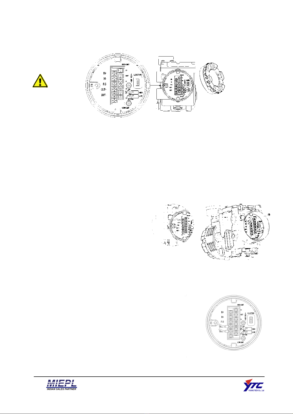
1.3 Explosion Proof Warning
Please ensure the unit is being used and installed within the explosion proof certified
environment.
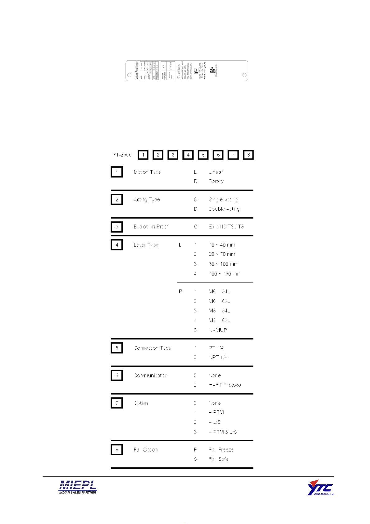
YT-2600 series explosion proof grade is Ex d IIC T6 and can be used in zone 1 and 2.
Explosion proof type of cables and gaskets should be used, when explosion gases are