Lift Products Roto-Max Troubleshooting guide

Roto-Max
Work Posioner
Operaon
Maintenance
Li Products Inc.
P.O Box 349
Elm Grove Wisconsin 53122-0349
PH: 877-543-8776 FX: 262-521-5725
Manual #19950
1

2
WARNING
Do not operated this li table unless you have been trained and authorized to do so and have
read all warnings and instrucons in operator’s manual and on the li table.
Do not operate this li table unl you have checked its condion. Give special aenon to
electrical system, li system (including limit switch), guards and safety devices.
Operate li table only from designed operang posion. Never place and part of your body into
the structure. Keep feet clear of li table.
Do not overload li table. Check capacity plate for load weight and loading informaon.
Before liing, be sure load is centered.
Do not handle unstable or loosely stacked loads. Use special care when handling long, high, or
wide loads.
Watch out for obstrucon, especially overhead.
Do not li personnel.
Do not allow anyone to place any part of their body into or under the liing mechanism.
When leaving li table, fully lower liing mechanism. When leaving li table unaended, also
disconnect power.

3
SECTION 1
DESCRIPTION
1-1 INTRODUCTION
This preliminary publicaon describes the Li Table Series manufactured by Li Products, Inc.
Elm Grove, Wisconsin 53122-0349. Included are operaon instrucons, planned maintenance
instrucons, lubricaon procedures, and a paral parts list with parts locaon illustraons.
For any maintenance instrucons not contained in this preliminary publicaon, contact Li
Products Customer Service. Be prepared to give model number, serial number, liing capacies
and li travel of your table.
The model number, serial number and liing capacies are stamped on the name plate
(Figure 1-1). The li travel can be determined by subtracng the lowered height from the el-
evated height.
Users shall comply with all requirements indicated in current edion of A.N.S.I MN29.1. By
following these requirements and the recommendaons contained in this manual, you will
receive many years of dependable service from your li table.
Figure 1-2 shows the locaon and idencaon of the decals. Also listed is the touch-up paint
as well as the locaon of the name plate. Figure 1-3 shows the locaons of the li table main
components.
Note: The user shall see that all name plates and markings are in place and are maintained in a
legible condion.

4
Serial No:
Model:
Liing Capacity:
Service Weight:
Edgeload Capacity:
Axel Load Capacity
1-2. GENERAL DESCRIPTION
The li tables have been designed primarily for indoor applicaons. All models are similar in
design but dier in capacity, li height and plaorm size.
The li and lower moon is controlled by a control box aached by a cord. The control box is
mounted on a magnet for easy aachment to a convenient locaon.
1-3 SAFETY FEATURES
The li tables are designed and engineered to provide maximum safety for operator and
payload. Some of the safety features incorporated into the design are:
• All control funcons automacally return to “OFF” when released.
• Travel limit switch to restrict li moon above the preset limit
• Pressure compensated ow control valve regulates maximum lowering speed within
prescribed limits
• Maintenance Safety Bars to support li table during maintenance operaons.
• High visibility color scheme of the li table provides visual alert of its presence
INSTALLATION
2-1. RECEIVING INSTRUCTIONS
Upon receipt, visually inspect the li table. If any damage is found, report it to the carrier and to
your Li Products dealer immediately.
Remove all packing and strapping material. Check the plaorm size type of electrical system,
ect., to be sure the li table is correct for the intended applicaon.

5
2-2. INSTALLATION INSTRUCTIONS
WARNING: Modicaon and addions which aect capacity and safe operaon shall not be
performed by the customer or user without manufacturers prior wrien approval.
1. Clean the installaon area.
CAUTION: The li table should only be picked up from under the base. Do not li the table by
the plaorm.
2. Posion the li table in the desired posion.
NOTE: The li table comes pre-wired with a 10 foot power cord. Check the decal located on the
electrical box for the voltage/phase and be sure you have the same power supply source. The
proper plug and mang receptacle must be purchased and installed by the user.
NOTE: Units equipped for a 115 volt power supply need to have a separate 20 amp rated circuit
and proper wiring to ensure an actual 115 volts at the li table electrical box when operang
under a full load.
3. Install the proper plug and connect to the power receptacle.
4. Using the control box, check for proper operaon. When the UP buon is depressed
the plaorm should remain staonary. When the DOWN buon is pressed the
plaorm should lower
5. Raise the plaorm and swivel both maintenance safety bars against the base. Lower
the plaorm unl the safety base contact the end of the base and the plaorm does
not lower any further.
6. Check for oil in the hydraulic reservoir. (note: Unit is supplied with oil).
7. The base contains pre-drilled mounng holes. Mark the locaon of these holes on the
oor.
8. Shi the li table over, drill holes in the oor and install anchors.
9. Reposion the li table and shim unl lever. Make sure the li table is fully supported
along its enre base with shims or concrete grout.
10. Bolt the base to the anchors installed in the oor.
11. Raise the plaorm and posion the maintenance safety bars in their proper
disengaged posion.
12. Operated the li table through several complete cycles and check for pinched hosed
or hydraulic leaks from ngs that may have loosened during shipping.

OPERATION
3-1. GENERAL
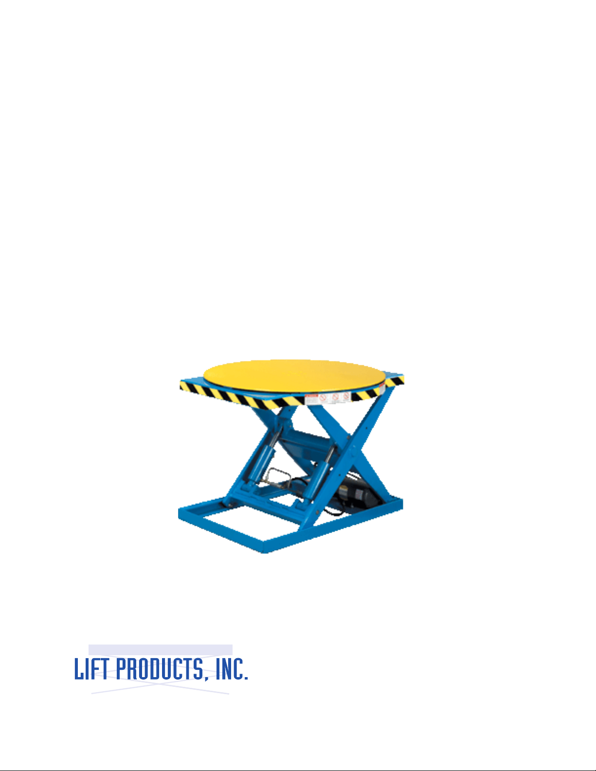
This secon gives detailed operang instrucons for the li table. Roune precauons are
included for safe operaon.
3-2. OPERATING PRECAUTIONS
WARNING: Improper operaon of the li table may result in operator injury or load and/or li
table damage. Observe the following precauons when operang the li table.
1. Do not operate this li table unless you have been trained and authorized to do so.
Read all warning and instrucons in this manual and on the li table.
2. Do not operate this li table unl you have checked its condion. Give special
aenon to electrical system, li system, guards and safety devices.
3. Do not exceed the rated capacity (see name plate). Overloading may result in
damage to the hydraulic system and structural components. Refer to paragraph 3-3.
4. Do not handle unstable or loosely stack loads. Use special care when handling long,
high, or wide loads to avoid pping, loss of load, or striking bystanders.
5. Check for obstrucons when raising or lowering the li table.
6. Operate li table only from design operang posion. Never place any part of your
body into the structure. Keep feet clear of li table.
7. Watch out for obstrucons overhead.
8. Do not li personnel.
9. Do not allow anyone to place any part of their body into or under the liing
mechanism.
10. When leaving li table, fully lower liing mechanism. When leaving li table
unaended, also disconnect power.
3-3. LOAD CAPACITY
The load capacity rang is stamped on the name plate. This load capacity assumes the load is
uniformly distributed and centered on the plaorm.
3-3.1. STATIC EDGE LOADS
The li table is designed for uniformly distributed centered loads. If the load is lied at the
sides or ends of the plaorm, the stac edge load stamped on the name plate should not be
exceeded.
6

6
3-3.2. AXLE (ROLLING EDGE) LOADS
When a load is rolled onto the plaorm, the li table should be fully lowered. The axle load
stamped on the name plate should not be exceeded.
3-4. BEFORE OPERATION
Table 3-1 covers important points on the li table which should be checked prior to operaon.
Depending on use, some li tables may require addional checks. When the li table is used on
a round-the clock basis, it should be examined aer each shi.
Figure 3-1 shows a sample format for a Operator Check List which can be modied as necessary
to t your operaon.
WARNING: Periodic maintenance of this li table by a QUALIFIED TECHNICIAN is required.
CAUTION: A QUALIFIED SERVICE TECHNICIAN should check the li table monthly for proper
lubricaon, proper uid levels, motor maintenance and other areas specied in Secon 4.
WARNING: If the li table is found to be unsafe and in need of repair, or contributes to an
unsafe condion, report it immediately to the designated authority. Do not operate it unl it
has been restored to a safe condion. Do not make any unauthorized repairs or adjustments.
All service must be performed by a qualied maintenance technician.
7

Table 3-1. Operator Check List
8
ITEM
• Decals&NamePlate
• Hardware
• HydraulicLines
• Lift&Lower
• LiftCylinders
• LiftLimitSwitch
• LiftMotor
• PivotPoints
• Platform
• Power&SwitchBoxCords
• PushButtons
• Rollers
• Drift
PROCEDURE
• Checkthatalldecalsandnameplateare
inplaceandlegible.
• Checkforsignsoflooseormissing
hardware.
• Checkforcutorfrayedhose,leaking
ttingsordamagedlines.
• Checkforproperoperationofliftand
lowertotheirmaximumpositions
• Checkforsignsofleakage
• Checkforlooseorbentmounting.Check
thatthelimitswitchshutsoffthepump
motoratthepresentplatformheight.
• Checkforgrindingorlaboringsounds
• Checkforsmoothpivotingaction
• Checkfordentsorwarpage
• Checkforcutorfrayedcord
• Checkthatthepushbuttonsdonotstick
ormalfunctionwhenpressed
• Checkupperandlowerrollersforsignof
wear
• Checkforexcessivedownwarddrift
whencontrolsareinneutralposition

8 9
3-5. OPERATION
3-5.1 TRAINING
Only operators trained to adhere strictly to the operang instrucons shall be permied to
operate the li table.
The user shall ensure that operators understand that safe operaon is the operator’s
responsibility. The user shall also ensure that operators are knowledgeable of and observe the
safety rules and pracces.
An eecve operator training program should center around company’s policies, operang
condions , and li tables, The program should be presented completely to all new operators
and not condensed for those claiming previous experience.
3-5.2 LOADING
1. Always center the load on the plaorm as much as possible. Refer to paragraph 3-3
for load capacity.
2. If the load is lied at the sides or ends of the plaorm, refer to paragraph 3-3.1 for
stac edge load capacity.
3. When a load is rolled onto the plaorm the li table should be fully lowered. Refer
to paragraph 3-3.2 for rolling edge load capacity.
3-5.3 RAISING
CAUTION: Do not exceed the rated frequency of operaon indicated on the li table.
Pressing and holding the UP push buon acvates the pump and motor causing the cylinder(s)
to extend and the plaorm to raise. If the table is overloaded, the relief valve should open,
prevenng buildup of excessive pressure. When the li table reaches a preset height the li
limit switch will cause the li table to stop. When the UP push buon is released the plaorm
with remain in posion.
CAUTION: Do not connue to press the UP push buon if the li table has reached the end
of its travel or is not raising. The pump and/or motor can be permanently damaged by doing
this.
3-5.4 LOWERING
Pressing and holding the DOWN push buon acvates the lower solenoid valve. Oil from the
cylinder is directed back to the reservoir, allowing the li table to lower at a controlled rate.
When the DOWN push buon is released, the plaorm will remain in posion.

10
Electric Li Table
Daily Operator Check-O List
Date
Truck No.
Dept
Operator
Model No.
Shi
CHECK
Decals & Name Plate
Condion of Hydraulic Lines
Condion of Power
& Switchbox Controls
Li Lower Controls
Li Limit Operaons
Missing Hardware
Hydraulic Leaks, Cylinders,
Valves, Hoses, Etc.
Pivot Points
Rollers
Li Motor
Plaorm
No Excessive Dri
OK NEEDMAINTENANCE

11
NOTES

12
4-1. GENERAL
Planned maintenance consists of periodic visual and operaonal checks, parts inspecon,
lubricaon and scheduled maintenance designed to prevent or discover malfuncons and
defecve parts. The operator performs the checks in Secon 3, and refers any required servicing
to a qualied maintenance technician who performs the scheduled maintenance and required
servicing.
WARNING: Modicaons and addions which aect capacity and safe operaon shall not be
performed without manufacturers prior wrien approval.
4-2. MONTHLY AND QUARTERLY CHECKS
Table 4-1 is an inspecon and service chart based on normal usage of equipment eight hours
per day, ve days per week. If the li truck is used in excess of forty hours per week, the fre-
quency of inspecon and service should be increased accordingly. These procedures must be
performed by a qualied technician or your Li Products service representave.
INTERVALINSPECTIONORSERVICE
Monthly Checkconditionofpumpmotor
Monthly Checkconditionofhydraulicttingandhoses
Monthly Checkcasterwheels(ifequipped)forwearandproperfunction
Monthly Inspectwiringforlooseconnectionsanddamageinsulation
Monthly Lubricateunit(SeeTable4-3)
Quarterly Checkcylinderwiperandpacking
4-3. LUBRICATION
Refer to table recommended types of grease and oil. Table 4-3 in conjuncon with gure 4-1
idenes the items required lubricaon.
Table 4-2 Recommended Lubricants and Oils.
No. 1 Grease-Lithium base, general purpose.
No. 2 Hydraulic oil-heavy duty with viscosity of 150 SUS
(in temperature below 32 degree F use 100 SUS) foam suppressing agent
and rust and oxidaon inhibitors.
Part No. 900855 ( 1 gallon)
900893 (1 quart)
No. 3 Moly-Grease-Dow Corning Molykote 44 (contains silicone)
Part No. 055753

13
4-3.1. LIFT CYLINDER
1. Raise the plaorm
2. Swivel both maintenance safety bars down against the base.
3. Lower the plaorm unl the safety bars contact the end of the base and the plaorm
does not lower any further.
4. Loosen the bolt securing the boom of each li cylinder to the base.
5. Parally collapse the cylinder rod and li the boom of the cylinder out of the
channel in the base.
6. Apply a light coat of moly-grease to the channel. See Table 4-2, No.3.
7. Posion the cylinder(s) in the channel and secure with the mounng bolt(s).
8. Raise the plaorm and posion the maintenance safety bars in their proper
disengaged posion.
FIG. 4.1
Index
No. Location Method of
Application
Type Table
4-2 Application of Lubricant
1Hydraulic
System N/A No.2
AddHydraulicoiltoreservoirthrough
breatherport.Note:Unitissuppliedwith
oil.Donotoverll.
2Upper
Rollers Gun No.1 Pressurelubricate(twottings)
3Lower
Rollers Gun No.1 Pressurelubricate(twottings)
4Pivot
Points Gun No.1 Pressurelubricate(twottings)
5Lift
Cylinder Brush No.3 Refertoparagraph4-3.1

14
SECTION 5
TROUBLESHOOTING
5.1 GENERAL
Table 5-1 serves as a guide to determine possible causes of trouble. Refer to electrical wiring
diagrams (Figure 5-1 to 5-4) as a supplement to the troubleshoong chart or when tracing an
electrical circuit.
Table 5-1. Troubleshooting Chart
MALFUNCTION
Doesnotraisebutpump
motorisrunning
Platformraisesslowly
Doesnotraisebutpump
motornotrunning.
Platformdoesnotlower.
Platformcreepsdownward
underload.
CORRECTIVE ACTION
Addoiltoreservoir.Referto
nameplateformaximumload
capacity.Removeandclean.
Replace.
Refertonameplatefor
maximumloadcapacity.
Lubricate.
Replace.
Overhaulcylinder.
Replace.
Checkpowersource.
Repairasrequired.
Replace.
Correctcondition.
Replace.
Repairasrequired.
Lookforloosettingsinthe
hydraulicline.Repairttings.
Lookforoilontopofthe
cylinderpacking.Overhaul
cylinder.
Replace.
Replace.
PROBABLE CAUSE
a.Oillevelislow.
b.Loadheavierthancapacity.
c.Filterisclogged.
d.Defectivepumpormotor.
a.Loadheavierthancapacity.
b.Lackoflubrication.
c.Defectiverollers.
d.Defectivepump.
e.Defectivecylinder.
f.Defectivereliefvalve.
a.Noelectricalpower.
b.Defectivecontrols.
c.Defectivemotor.
a.Maintenancesafetybar
orobstructionblocking
movement.
b.Defectiveloweringsolenoid
valve.
c.Defectivecontrols.
a.Externalleakinhydraulic
system.
b.Defectivepackagingin
cylinder
c.Defectivesolenoidvalve.
d.Defectivereliefvalve.

15

16

17
Roto-Max Parts List
Description Models Part Number
ElectricMotor RTMX-25HS(115V) 34H54X307
ElectricMotor RTMX-30(115V) 34H54X307
ElectricMotor RTMX-35(230/4603ph) 34H716W640G1
ElectricMotor 230/4603phaseoption 34H716W640G1
Transformer 230/4603phaseonly 125-E060
PumpAssembly RTMX-25HS G1106F1A120R15
PumpAssembly RTMX-30/35 G1104F1A125R15
CylinderKit AllModels 125-R012
Cylinder AllModels 125-2/M92
FlowControlValve AllModels 125-1352/1.5
SteelHydraulicLine AllModels 125-36/7290
PressureHose AllModels 125-31RB
PushButtonControl AllModels 125-990901
FootControlAssembly AllModels 125-5769
MotorStarter AllModels115Volt 125-RSC22
MotorStarter AllModels230/4603ph 125-RCS18
LimitSwitch AllModels 125-RSH
CenterRotateBearings AllModels 125-W-2
OuterRotateBearings AllModels 125-6204ZZ
CamFollower/ScissorArm AllModels 125-CNB48SB
NOTE: SPECIFY MODEL AND SERIAL NUMBER WHEN ORDERING PARTS.

REGISTRATIONINFORMATION
(Tovalidateyourwarrantyandreceiveupdatedservicebulletins,pleasecompletethisform)
Date_______________ModelNo.________________SerialNo._______________
HowdidyoursthearofLiftProducts?
____MagazineAd(Specifywhichmagazine)______________________________________
____Recommendedbyadealer(NameofDealer)__________________________________
____Receivedinformationinthemail
____Internet
____Other(Pleasespecify)_____________________________________________________
WhatfactorscausedyoutochooseLiftProducts?_______________________________________________
_______________________________________________________________________________________
_______________________________________________________________________________________
Describehowandwhereproductsarebeingused?_______________________________________________
_______________________________________________________________________________________
_______________________________________________________________________________________
Nameofpersoncompletingthisform_________________________________________________________
Title___________________________________________________________________________________
Company_______________________________________________________________________________
StreetAddress___________________________________________________________________________
City,State,Zip___________________________________________________________________________
Phone________________________FaxNo.___________________________________________________
PurchasedFrom:
NameofDealer__________________________________________________________________________
StreetAddress___________________________________________________________________________
City,State,Zip___________________________________________________________________________
PhoneNo._____________________FaxNo.___________________________________________________
Pleasefaxthisformto262-521-5725.
Table of contents
Popular Valve Positioner manuals by other brands

CONFLOW
CONFLOW Power Genex PPR Series Installation and maintenance manual

Flowserve
Flowserve D20 Series Installation operation & maintenance

Parker
Parker 404LXR Series product manual

Genebre
Genebre 5810 04 Installation, operation & maintenance manual

Samson
Samson TROVIS 3730-3 manual

cam
cam PL Series operating manual

Burkert
Burkert 8791 operating instructions

Baker Hughes
Baker Hughes Masoneilan SVI FF quick start

RTK
RTK SR-3300 Installation and operating instructions

Flexco
Flexco RBP1 Installation, operation and maintenance guide

JOMAR
JOMAR AEP-100 Installation, operation & maintenance instructions

Lika
Lika RD4 user guide