5
ASSEMBLY
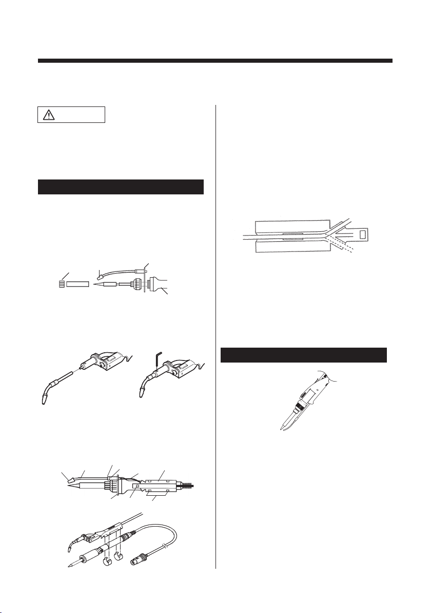
4-4. Setting the Solder If there is any solder in the tube, remove it
before installing the new solder.
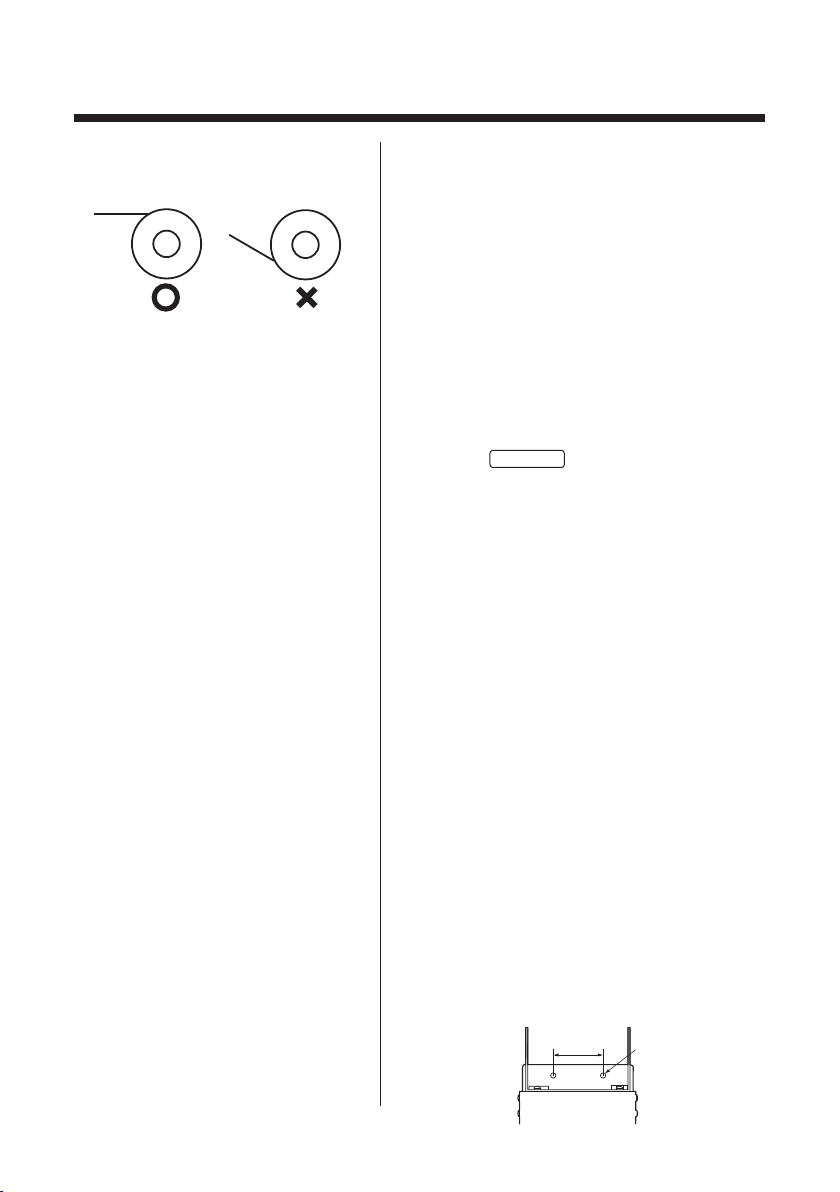
(a) Pass the solder bobbin shaft through the
solder bobbin and attach the shaft to the
rear of the station. As shown left, attach the
shaft so that the solder is fed from the top
of the bobbin.
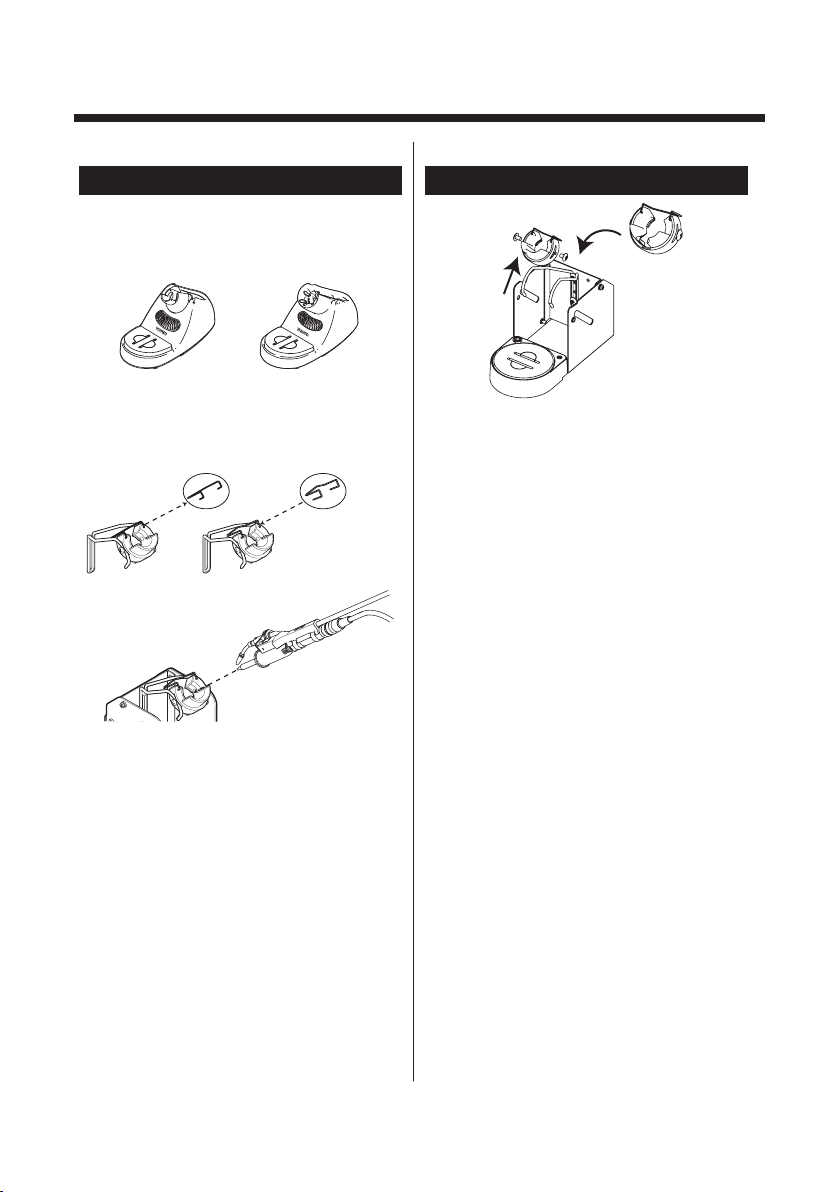
(b) Pass the solder through the supply nozzle.
(c) With pressing release lever, put the
inserted solder of approx. 10 mm (0.4
in.) into the feed nozzle through between
tension gears.
(d) Turn the power switch ON and set the
mode to
MANUAL
.
(e) Pressing the feed switch (or footswitch),
and feed the solder.
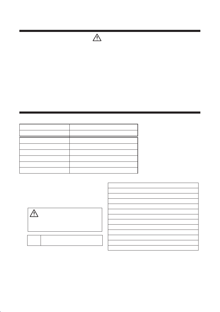
4-5. Changing the Solder
Diameter
The following parts may need to be
changed in order to accommodate a
change in the solder diameter or type of
soldering iron used.
Solder dia. adjustment ring
Nozzle
Guide pipe assembly Tube unit
Change these parts as necessary
according to the procedure below.
(a) Power switch off. Open therelease lever
androll back the left solder to the bobbin.
(b) Remove the tension gear guide shaft, and
replace the solder dia. adjustment ring
according to desired solder dia. Remove
the tension gear guide shaft turning with a
spanner or pliers.
(c) Replace the guide pipe assembly if it is
necessary.
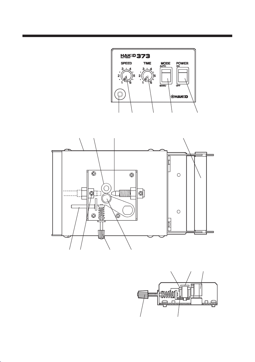
4-6. Vertical Mounting
The HAKKO 373 can be mounted vertically.
Mount as shown in the figure.
←
46mm 2-φ4.2
6
OPERATION
Solder will be fed by pressing the feed switch (or foot switch).
■MODE □AUTO MODE
If you press the feed switch, solder will be
fed with set time and speed independently
of length of pressing time.
□MANUAL MODE
Solder will be fed with set speed during
pressing the feed switch.
■Setting for Feed Time
and Feed Speed
Set the speed before the time. For the
setting speed, both
&
are
effective, but only
is effective for
setting time.
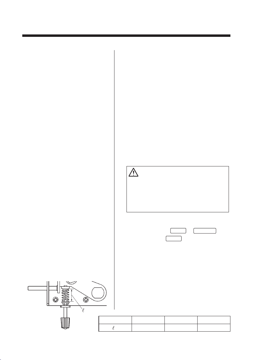
■Adjustment of Tension When adjust the tension, be sure that not
the gear to be slipped during feed solder,
or do not force to feed solder slipping gear
when solder clog.
Set the tension gear loosely for fine solder
(ø0.6mm, 0.8mm/0.024 in., 0.031 in.).
Refer to the following chart.
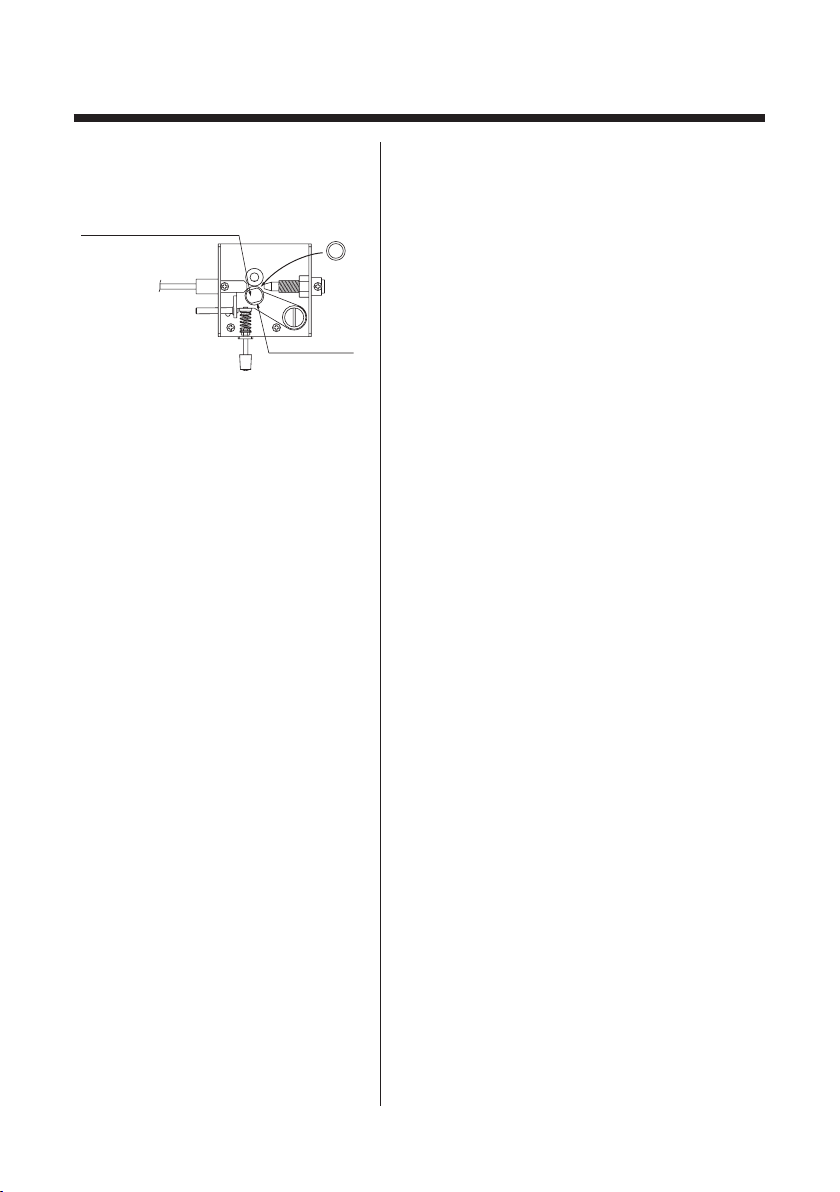
■Adjustment of the
Nozzle Position
If there is a solder in the guide pipe, pull it
out of the pipe and then adjust the nozzle
position.
(a) Loosen the pipe securing nut, turn the
guide pipe to adjust the nozzle position,
and then tighten the loosened pipe
securing nut.
Solder Dia. ø0.6mm
maximum
ø1.0mm
14mm
ø1.6mm
10mm
CAUTION
Do not over tighten the pipe securing nut.
Otherwise, the guide pipe can break.
This adjustment must be done during the
iron tip is cold. Otherwise, you may suffer
burns.