manuals.online logo
Brands
  1. Home
  2. •
  3. Brands
  4. •
  5. Mikado
  6. •
  7. Toy
  8. •
  9. Mikado LOGO 800 User manual

Mikado LOGO 800 User manual

LOGO 800
Manual
Mikado Model Helicopters GmbH • Graf-von-Schwerin-Str.40 • 14469 Potsdam • Germany
phone +49 (0)331 23749-0 • fax +49 (0)331 23749-11 • www.mikado-heli.de
© Mikado Model Helicopters GmbH 2019, V1.0
Before powering on the helicopter:
Never operate the helicopter inside closed rooms as this helicopter is intended for operation outside and may only be operated in
sites where operation of Radio Control models is permitted. . Keep the helicopter at safe distance to any persons or live animals
at all times. When trimming, keep a minimum distance of 10 yards for safety and never operate the helicopter alone. Always take
someone with you, who can help in emergency situations.
The helicopter must also not be operated in the following circumstances:
• when children are present or in places where people are gathering
• close to houses or in park areas
• inside any rooms or buildings
• places with limited space
• in adverse weather conditions, such as rain, snow, hail or during strong winds
• Near trees or High Tension wires
Techical specifi cations which must be obeyed during the operation of the
LOGO 800:
• maximum rotor head rpm: 1800 U/min.
• maximum pitch travel: +/- 12°
• Length of rotor blades: 750 to 810mm
• Lipo battery: 12-14S Lipo Batteries
• admissible temperature 5° - 35° Celsius
If these values are exceeded, the electronic components may experience overload. This may result in damage or a crash of the
helicopter.
Before the fi rst fl ight, you must check proper functioning of the motor, the ESC and the VBar. To do this, please refer to the
respective manuals. For safety reasons, these tests should be performed without mounting the main rotor blades and the tail
rotor blades. It is advisable to fl y moderately during the fi rst fl ights. This is because you need to get used to the new size of this
helicopter during the fi rst few fl ights. Do not underestimate the size and power of this helicopter. Keep a safe distance from the
ground to provide for ample reaction time.
***Tips for fl ying your Logo 800 in a safe way***
In our rigorous testing we fl ew the Logo 800 in very aggressive maneuvers and did not fi nd it to be susceptible to failure, or boom
strikes. However, due to the size of this model it is our recommendation to you that it should not be fl own in the same way which
you fl y a small helicopter or 700 size competition machine, particularly in aggressive 3D maneuvers. Please note the following
tips on how to fl y your 800 in order to ensure the long and healthy life of your model.
1. . If you will be fl ying aggressive 3D maneuvers, you MUST fi rst install the 2 x 90 shore dampers in the “Hard Damper
Confi guration” Please note more about this on page #15.
2. Do not do maneuvers which give large amounts of backwards elevator, and negative collective pitch at the same time.
Especially do not do this in a quick jab, or aggressive way. If you will give both of these commands at the same time you should
do them more smoothly. Otherwise it may result in catastrophic boom strike.
3. Utilize good pitch management when fl ying this helicopter. When fl ying you should only give large amount of collective pitch,
with low amount of cyclic, or high cyclic amount with low amount of collective pitch. But not both at the same time.
4. Do not attempt to do aggressive fl ying at low RPMs. If you want to fl y aggressive maneuvers, please use at least 1800rpm of
head speed. If you fl y with lower RPM, then you must also fl y the model in a smoother way.
5. High amounts of collective pitch with rapid right rudder inputs should be avoided. The increased torque from the collective pitch
and the right tail rotor input (against torque) will put huge amounts of stress on the tail rotor drive train.
6. If you fl y mainly with Low RPM (below 1400rpm), you can use longer tail rotor blades (120-130mm) to get a better tail authority.
But do not attempt to fl y higher 6. rpm with larger tail blades.
Index
Safety Instructions/ Tools for Assembly & RC Equipment 2
1 Chassis 3
1 Chassis and Landing Struts 5
2 Servo Mounting 7
3 Main Gear 8
4 Motor Installation 9
5 Tail Rotor 10
6 Torque Tube 11
7 Tail Boom Mounting 12
8 Tail Boom Brace 13
9 Swashplate 14
10 Rotor Head 15
11 Rotor Head Linkage 16
12 Wiring RC Components 17
13 Mounting ESC/ Battery 18
14 Canopy and Overview 19
15 Overview Spare Parts Mainframe 20
16 Overview Spare Parts Tail Boom 23
17 Overview Spare Parts Tail Rotor 24
18 Overview Spare Parts Rotor Head 25
Thank you very much for your purchase of the Mikado LOGO 800. Prior to assembly, please read and understand this manual
completely and follow all instructions exactly. If any instructions are not clear to you or if you have any questions, please contact
us. You can reach Mikado on the LOGO-Forum on www.vstabi.info or contact the Mikado support hotline via email or phone. Do
not under any circumstances fl y this helicopter if you are unsure of setup or assembly.
This helicopter is not suitable for beginners. It is expected that you have some experience in assembling and operating an RC
helicopter (model size LOGO 400 to LOGO 600, for example). You are required to adhere to the safety instructions of this manual.
You must secure all screws in all components yourself. In addition, it is necessary that you secure all other screwed connection,
by which you will assemble the diff erent components of the LOGO. We recommended to use securing glue Loctite 243 (blue).
Please follow the recommendations of the Loctite manufacture and allow proper curing time for the Loctite prior to fl ying the
model.
Safety Instructions:
RC Helicopters are not toys and must be treated with due diligence. If you do not use this helicopter responsibly it can cause
of severe injury and immense damage. Inappropriate use of this product can result in injury or death. Each user must have the
appropriate knowledge and skill to operate any RC Helicopter. Manufacturer / reseller assumes no liability for the use or operation
of this helicopter.
You are responsible for any injury and damage that may be caused by this helicopter. It is recommended that your radio
components be tested prior to installing in this helicopter. Improper radio installation or inadequate battery voltage can result
in the loss of control of the helicopter. Proper knowledge of your radio equipment is required prior to fl ying this helicopter. You
must check if other persons are using an RC-controlled model or device simultaneously, as this may result in interference. If the
helicopter behaves in an unusual or strange way, you must land it immediately and turn off the power. Please meticulously check
all of your radio gear and fi nd/fi x the problem before you continue to operate the helicopter This is to avoid any accidents. Since
one irregularity can cause other defects or problems, an increased risk of failure will ensue, if the problem is not fi xed fi rst.
Additional precautions for the prevention of injuries or damage:
Before you power on the helicopter, you must ensure that all screws and associated hardware are secured. Even just one single
loose screw can cause the helicopter to become uncontrollable resulting in a crash or personnel injury.
Also it is very important that you must check the model frequently and exchange any parts that show signs of deterioration or
wear. Failure to complete frequent pre and post fl ight inspections will result in fl ying an unsafe model and increasing the risk of
damaging the helicopter and possibly injuring yourself and/or others. Use only original Mikado parts and electronic components
which are recommended by Mikado.
Always keep a minimum of 10 yards away from a spinning rotor head. Components that run hot such as the ESC and Motor
should never be touched until ample cool down time has been provided.
Perform overspeed maneuvers only at your own risk: overspeed maneuvers may overload the components
on the helicopter and lead to damage/a crash/injury.
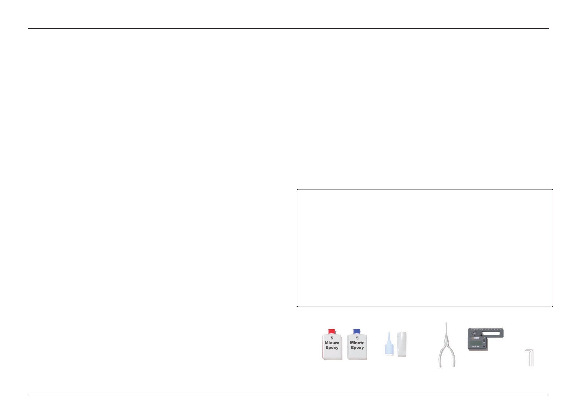
Hex Wrenches
1,5/2,0/2,5/3,0/4,0/6,0 mm
Grease
Ball
link
pliers
5
Minute
Epoxy
5
Minute
Epoxy
Pitch Gauge
Threadlock
Manual LOGO 800 - ©Mikado Model Helicopters GmbH - Page 2
1 2
Designed for servo with mounting
grommet (5 mm). In case the mounting
grommet is taller, please use longer
screws.
Select the corresponding mounting
plate, depending on your servo (10
or 11 mm distance between holes).
Bag 1+3
Manual LOGO 800 - ©Mikado Model Helicopters GmbH - Page 3
1 Chassis
M2x10
M3x12
M3 Stop M2 Stop
M2,5x8
M2,5x8
M2,5x6
M2,5x6
M2,5x8
4x
8x
8x
M2,5x6
M2,5x6
M2,5x8
1x M3x12
1x M2x10
1x
1x
M3
M2
Ø6
Ø4,8
15x21x4
1x
1x
2x
17 mm 17 mm
3x
5,5x59
Elevator Rudder
1
2
Bag 1
Use the included 2.5 mm
threaded rod to position
the 2.5 mm hex lock nuts
in the right hand side
frame.
Be sure to instert
the adapters
at this stage.
Manual LOGO 800 - ©Mikado Model Helicopters GmbH - Page 4
1 Chassis
M2,5 Stop
M2,5x6
M2,5x10
M2,5x12
M2,5x10
8x M2,5 Stop
4x M2,5x6
8x M2,5x10
5x
1x
M2,5x12
2,5x60
12x M2,5
14x25x62x
1234
5
6
7
Bag 1+5
Fix the end caps
with glue inside
the landing skids.
Do not overtighten
these screws.
Belt 486
Manual LOGO 800 - ©Mikado Model Helicopters GmbH - Page 5
1 Chassis and Landing Struts
9,5x6
6x13x5
6x13x5
9,5x6,5
schwarz/black
silber/silver
4x M3x3
M3x5
M3x5
M3x12
2,2x6,5
M3x22
M3x10
M3 Stop
M3 Stop
M2,5x12
M2,5 Stop
2,2x6,5
M3x22
M3 Stop
M3 Stop
M3x10
4x60
2x M3x22
4x M2,2x6,5
2x M3x10
4x
4x
M3x3
M3x5
4x M3x12
4x M3
1x
1x
1x
2x
M2,5
9,5x6,5
9,5x6
6x13x5
2x
1x
5,5x59
4x60
2x
2x
3x5x4
3x5x10
2x
1x M2,5x12
Bag 1
Only tighten the M3x20 screw
once you have mounted the tail
boom support.
Manual LOGO 800 - ©Mikado Model Helicopters GmbH - Page 6
1 Chassis
M3x10
M3x20
4x
2x
M3x10
M3x10
M3x20
Bag 3
Fix servo wire to the
bottom side of the servo
casing using electrical
tape or scotch tape.
Manual LOGO 800 - ©Mikado Model Helicopters GmbH - Page 7
2 Servo Mounting
M3x12
(2x)
Roll links/
Aileron left
Roll rechts/
Aileron right
17 mm 17 mm
2,2x13
2,2x13
2x M3x12
8x M2,2x13
Kugel/ball Ø6mm
2x
2x M3
Roll links/ Aileron left
1
2
3
4 5 6 7 8
Bag 4
Prior to mounting the main gear,
apply grease to both bevel
gears in the tail drive.
When mounted properly, the
main gear has approx. 1 mm
axial play.
Use the silicone tube provided as a
fl exible extension, to easily mount the
4x26 mm bolt in the tail gear.
Apply grease to the one way
bearing.
Manual LOGO 800 - ©Mikado Model Helicopters GmbH - Page 8
3 Main Gear
6x M2,5x10
14x20x0,3
M2,5x25 (4x)
M3x10
14x20x1
6x M2,5x10
2x M3x10
4x
1x
M2,5x25
4x26
1x
1x
14x20x1
14x20x0,3
Loctite
4x26
Loctite
12
34
Bag 6
Mounting the pinion:
1) position the pinion on the motor shaft so the grub screw
sits loosely in the fl at spot on the motor shaft.
2) Push motor and pinion against the main gear. The herring
bone gear helps with the proper alignment of pinion and
main gear.
3) There must be next to no backlash between main gear
and pinion. Check the gear mesh after the fi rst couple of
fl ights.
Manual LOGO 800 - ©Mikado Model Helicopters GmbH - Page 9
4 Motor Installation
M3x10
M3x10
M4x12 (x4)
5x M3x16
5x M3x16
4x M3x10
10x M3x16
a
b
c
d
4x M4x12
4x 4x8x1
5x10x4
Mount the
distance ring so
that its surface
with the shoulder
shows in the
direction of the
ball bearing.
Note that the disk with the smaller inner diameter needs to be
installed on the outside. The disk with the larger inner diameter is
installed on the inside. You can distinguish the two disks by sliding
them (temporarily) onto the 5 mm tail spindle. Only the disk with the
smaller inner diameter will sit tightly.
please apply grease here
Larger inner Ø
Smaller inner Ø
Bag 7
Proper Gear Mesh
Maintenance/ Adjustment
The Tail Gear position is set to a
good starting mesh with the factory
recommended shim placement. But
after 10-20 fl ights the gear mesh
will wear in, and likely needs to be
readjusted. You tighten the gear
mesh by shifting one of the 0.1 or
0.2mm shims from the rights side
of the bevel gear, to the left side of
the bevel gear. Only shift one shim
per time and then reassemble and
check the mesh. The gear mesh
should be set so that there is a very
slight amount of play between the
two bevel gears when rotating them
around, with just 1 or 2 positions
where there is no play between
the gears. If the gears are hard
to rotate or noisy when spinning,
then it is too tight. If there is play
between the gears all the way
around, then it is too loose.
After the initial wear in and
readjustment of the tail
gears, you should not have to
readjust it more. However, it
is recommended to check the
gear mesh periodically to ensure
proper gear mesh is maintained.
Manual LOGO 800 - ©Mikado Model Helicopters GmbH - Page 10
5 Tail Rotor
M2,5x6
M2,5x12
M2,5x16
M2,5 Stop
M2x12
M3x24
M3x8
7x10x0,5
3x7x0,5
M3x12
5x10x4
3x6x2,5
M2x10
M3x20
M3 Stop
2x
2x
1x
1x
1x
2x
1x
1x M2
M3x8
M3x20
M3x24
3x5x12,2
M2,5x16
M2x10
M2x12
2x
1x
2x
2x
4x
2x
2x
2x
1x
2x
1x
6x
M3
M2,5
3x7x0,5
5x10x4
5x10x4
3x6x2,5
7x10x0,5
5x7,8x0,6
3x5x0,5
4,5x2
M2,5x12
M2,5x12
M3x10
M2,5x8
6x9x0,1
6x9x0,2
6x9x0,1
2x M2,5x8
4x M2,5x12
2x M3x10
2x
2x
1x
M3x12
15x21x4
18x20x11,7
5x7,8x0,6
8x20x11,4
15x21x4
5x36
2x 6x9x0,2
2x 6x9x0,1
1x 5x36
(+1)
(+1)
6x9x0,2
1
23
4
5
Torque Tube assembly
Carbon tail rotor push rod
Bag 8 + 12
10 mm Shrink tubing 10 mm Shrink tubing 10 mm Shrink tubing10 mm Shrink tubing
Push the four ball bearing mounted plastic sleeves to the torque tube, use the 10 mm adhesive shrink tubing to hold the bearings in position.
Please ensure prior to inserting the torque tube that the tail boom is dirt-free
inside. If necessary clean it with a cloth.
Please apply a good amount of grease to the rubber o-rings and to the inside of
the tail boom before inserting the torque tube assembly into the tail boom.
Apply grease to the o-rings.
Sand the carbon
tube before glueing
the ball link adapters
in place.
Shrink tubing
Manual LOGO 800 - ©Mikado Model Helicopters GmbH - Page 11
6 Torque Tube
280mm 250mm 180mm 120mm
70mm
5 min Epoxy
5 min Epoxy
2x
2x
2x
2x M3
M3x16
3mm
M3x16
M3x16
Push the tail boom all the way into the chassis. Tighten all six
screws holding the tail boom fi rmly, making sure the drilled
holes for the rotation prevention in the tail boom are aligned
properly. Finally fi x the tail boom using the M3x10 hex screws,
from both sides.
Manual LOGO 800 - ©Mikado Model Helicopters GmbH - Page 12
7 Tail Boom Mounting
Bag 8+12
Sand the carbon tube
before glueing the ball
link adapters in place.
Tail Control Rod Guide
In order for the Tail Control Rod Guide to function
properly you must fi rst put approximately a
50mm length of tape on the boom where the
control rod guide will be. We recommend either
1 x piece of Black electrical tape
2 x piece of clear scotch tape
This will allow the Tail Control Rod Guide to clamp
properly, but not pinch the Tail Control Rod itself.
In addition, you only need to tighten the bolt
enough so that the Tail Control Rod Guide does
not rotate when applying slight pressure to it.
If you do not fi rst put the tape, or tighten the
bolt to much, the Tail Control Rod Guide will
clamp too much and pinch the tail control
rod guide not allowing it to move freely.
Important
Mount the ball links
90° to each other.
Manual LOGO 800 - ©Mikado Model Helicopters GmbH - Page 13
8 Tail Boom Brace
2x M3x40
4x Kugel/Ball Ø6mm
M3x14
M2,5x8
3x5x4
M3x40
M3 Stop
Kugel/Ball Ø6mm
M3 Stop
M3x20
Ø6mm
Ø6mm
M3x20
3x M3
5min Epoxi
2x 3x5x4
2x M3x14
2x M2,5x8
1 2 3
4
8 9
56 7
Note when mounting the ball links: One
side of the ball link will clip on easily. The
other one is too tight to clip on easily. The
brand name Gabriel must point outwards.
The ball of the swashplate ball runs a bit tightly
in the beginning. Please apply a few drops
of oil to the ball. This help in breaking in the
swashplaste during fl ight.
Bag 9
Aileron Elevator
Manual LOGO 800 - ©Mikado Model Helicopters GmbH - Page 14
9 Swashplate
48mm
29mm
4x7x0,8
4x7x0,8
Loctite
5x
2x
6x
M2,5x6
4x7x1
M3x47
2x
1x 3x47
Bag 10
Please apply grease here
Larger inner Ø Smaller inner Ø
Please apply grease to the O-rings
and to the inner surface of the yoke.
Only tighten and
secure these screws
after adjusting the
rotor head links.
Only finally tighten and
secure after mounting
the rotor head to the
main shaft.
Head Dampeners for 3D Flying
This kit comes standard with 6 x 80 shore dampers which is our “Medium Dampener Configuration”. The medium dampers are great
for smoother flying at all RPMs. You can use the Medium Dampers for Sport to gentle 3D flying at all RPM ranges. However, if you
fly aggressive 3D maneuvers with the medium damper set installed it will increase your chance of boom striking the model!!!
If you want to perform aggressive 3D maneuvers you ***MUST*** change out the outer dampener on each
side from a 80 shore dampener, to one of the 2 x 90 shore dampeners which are included.
This is the “Hard Damper Configuration” and dampers will go
90-80-80 — 80-80-90
Installing the 2 x Hard Dampers will make the model more suitable for aggressive 3D flying but may induce wobbles at certain RPM ranges.
Do not try to put more then 2 x 90 dampers in the head as this will over compress the head and can damage the thrust bearings.
However due to the size of the model, even with the Hard-Damper Configuration, not all type of aggressive
maneuvers can still be performed. Please refer to the section on how to fly the model on page 2
Only tighten and secure
these screws after adjusting
the rotor head links.
Use the stock washer from
the rotor blade box..
Manual LOGO 800 - ©Mikado Model Helicopters GmbH - Page 15
10 Rotor Head
4x M3x12
2x M3x16
Kugel/ball Ø6
2x
3x5x0,5
2x
6x12x1,5
10x20x6,5
2x
2x
1x M3x6
2x
2x
2x
M3x25
M6x12
M5x30
2x M5
M3x25
M3x12
M3x16
5x24x1
M5x30,
M3x6
3x5x0,5
M6x12
6x12X1,5
M4x25
1x M4x25
5x24x2
1 2
45 6
3
Note when mounting the ball links: One
side of the ball link will clip on easily. The
other one is too tight to clip on easily. The
brand name Gabriel must point outwards.
Tighten and secure the M4x25 screw in
the main rotor head, the M3x30 in the
blade holders and the M3x25 in the swash
plate driver after mounting and adjusting
the rotor head and the linkages.
Bag 10
Manual LOGO 800 - ©Mikado Model Helicopters GmbH - Page 16
11 Rotor Head Linkage
27mm
4x
BEC/receiver battery:
We highly recommend using a BEC that can provide two power
leads to the Receiver/RC Components.
Wiring:
Please note: All wires must be placed in such a way that they
cannot be damaged by any sharp edges during operation of
the helicopter. Please apply the fabric tube and the edge guard
provided in this kit. Both types of protection are also available
individually from Mikado.
Battery
Manual LOGO 800 - ©Mikado Model Helicopters GmbH - Page 17
12 Wiring RC Components
ROLLSERVO LINKS
ROLLSERVO RECHTS
1
2
3
Before each fl ight make sure that the battery plate
is secured with both quick release mechanisms.
In case the battery plate can only be inserted into
the chassis with diffi culty in the beginning, please
apply a small amount of silicone oil at the edges.
Bag 11
Manual LOGO 800 - ©Mikado Model Helicopters GmbH - Page 18
13 Mounting ESC/ Battery
Bag 09
If you want to use the included edge protector, you have to enlarge the cut-
outs, for a perfect fi t. Do a couple of small iterations and check in between,
until the canopy sits tightly and braceless. Only then glue the edge protector.
Canopy Mounting
The Canopy of the Logo 800 is very large, and therefore requires four mounting points, rather then the
standard two mounting points. The 2 extra mounting points in the front ensure that the canopy mounts
fi rmly on the chassis and does not move.
One special feature of the Logo 800 Canopy is that the wrap around canopy design. This back area
is connected via two pins and magnets. Please take your time and be gentle when sliding the canopy
around the main shaft during mounting and dismounting otherwise you may damage your canopy.
Before each fl ight you should check that the canopy is mounted properly and securely. If the canopy
sits loosely it may interfere with the swashplate linkages, or wearout prematurely. If the canopy comes
off in fl ight likely your model will crash.
This canopy is 100% hand made. Small irregularities in the surface, the airbrush design and color are
normal. They do not constitute a reason for complaint.
IMPORTANT NOTE:
Taking the Canopy On and Off requires a quite specifi c procedure. Please scan this QR code and watch
our informational video about the easiest way to take the canopy on and off . www.uroehr.de/vtube/v/334
If you do not follow these steps, then you may fi nd diffi culties in mounting your canopy and may even
damage it.
Manual LOGO 800 - ©Mikado Model Helicopters GmbH - Page 19
14 Canopy and Overview
4x
4x
4,5x2
Manual LOGO 800 - ©Mikado Model Helicopters GmbH - Page 20
15 Overview Spare Parts Mainframe
5015
5332
4517
4517
5017
5018
4515
5353
5020
4601
4099
5021
5022
4522
4524
5055 4516
4521
4521
4523
5022
5354

Other Mikado Toy manuals

Mikado LOGO 200 User manual

Mikado

Mikado LOGO 200 User manual

Mikado Logo 600 User manual

Mikado

Mikado Logo 600 User manual

Mikado Logo 600 SX User manual

Mikado

Mikado Logo 600 SX User manual

Mikado Logo 500 User manual

Mikado

Mikado Logo 500 User manual

Mikado LOGO 10 3D User manual

Mikado

Mikado LOGO 10 3D User manual

Mikado Logo 480 User manual

Mikado

Mikado Logo 480 User manual

Mikado LOGO 550 SE User manual

Mikado

Mikado LOGO 550 SE User manual

Mikado Logo 500 SE User manual

Mikado

Mikado Logo 500 SE User manual

Mikado GLOGO 690 User manual

Mikado

Mikado GLOGO 690 User manual

Mikado Logo 500 SE User manual

Mikado

Mikado Logo 500 SE User manual

Mikado LOGO 700 User manual

Mikado

Mikado LOGO 700 User manual

Mikado Logo 400 SE User manual

Mikado

Mikado Logo 400 SE User manual

Mikado LOGO 500 DX User manual

Mikado

Mikado LOGO 500 DX User manual

Mikado LOGO 550 SX User manual

Mikado

Mikado LOGO 550 SX User manual

Mikado LOGO 20 User manual

Mikado

Mikado LOGO 20 User manual

Mikado LOGO 10 User manual

Mikado

Mikado LOGO 10 User manual

Mikado LOGO 14 Carbon User manual

Mikado

Mikado LOGO 14 Carbon User manual

Mikado LOGO 700 User manual

Mikado

Mikado LOGO 700 User manual

Mikado Logo 690 SX User manual

Mikado

Mikado Logo 690 SX User manual

Mikado VBAR User manual

Mikado

Mikado VBAR User manual

Mikado LOGO 600 SE User manual

Mikado

Mikado LOGO 600 SE User manual

Mikado LOGO 200 User manual

Mikado

Mikado LOGO 200 User manual

Mikado LOGO 550 User manual

Mikado

Mikado LOGO 550 User manual

Mikado Logo 600 SX User manual

Mikado

Mikado Logo 600 SX User manual

Popular Toy manuals by other brands

Redcat Racing Tsunami Pro instruction manual

Redcat Racing

Redcat Racing Tsunami Pro instruction manual

Accucraft trains SP 2-10-2 F4/F5 instruction manual

Accucraft trains

Accucraft trains SP 2-10-2 F4/F5 instruction manual

Faller MODERN FIRE STATION instructions

Faller

Faller MODERN FIRE STATION instructions

LeapFrog PAW PATROL RYDER'S PLAY & LEARN PUP PAD instruction manual

LeapFrog

LeapFrog PAW PATROL RYDER'S PLAY & LEARN PUP PAD instruction manual

BRITAX RÖMER Dolls Pram manual

BRITAX RÖMER

BRITAX RÖMER Dolls Pram manual

Mega Construx Despicable Me FND01 manual

Mega Construx

Mega Construx Despicable Me FND01 manual

Haute Decor DCYD0010 manual

Haute Decor

Haute Decor DCYD0010 manual

PARKZONE Ultra Micro Mini Vapor instruction manual

PARKZONE

PARKZONE Ultra Micro Mini Vapor instruction manual

LEGO DUPLO 5748 Building instructions

LEGO

LEGO DUPLO 5748 Building instructions

anko Cat Scratcher Box Halloween quick start guide

anko

anko Cat Scratcher Box Halloween quick start guide

Faller Urban dwelling house Assembly instructions

Faller

Faller Urban dwelling house Assembly instructions

BMI Carat manual

BMI

BMI Carat manual

TILLIG BAHN 01446 quick start guide

TILLIG BAHN

TILLIG BAHN 01446 quick start guide

AeroWorks YAK 54 ARF-QB Assembly manual

AeroWorks

AeroWorks YAK 54 ARF-QB Assembly manual

Eduard Il-2m exterior quick start guide

Eduard

Eduard Il-2m exterior quick start guide

MTHTrains GG-1 Operator's manual

MTHTrains

MTHTrains GG-1 Operator's manual

3D AEROWORKS Yakovlev Yak-3 Assembly manual and user guide

3D AEROWORKS

3D AEROWORKS Yakovlev Yak-3 Assembly manual and user guide

Mattel Disney PLANES Y3154 quick start guide

Mattel

Mattel Disney PLANES Y3154 quick start guide

manuals.online logo
manuals.online logoBrands
  • About & Mission
  • Contact us
  • Privacy Policy
  • Terms and Conditions

Copyright 2025 Manuals.Online. All Rights Reserved.