2 3
click
BOARDS™
www.mikroe.com
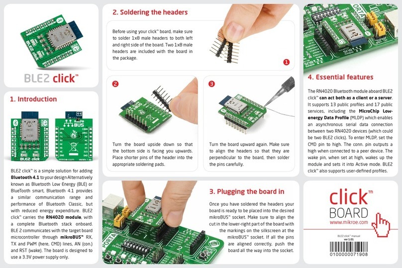
2. Soldering the headers
3. Plugging the board in
Once you have soldered the headers your
board is ready to be placed into the desired
mikroBUS™socket. Make sure to align the cut
in the lower-right part of the board with the
markings on the silkscreen at the mikroBUS™
socket. If all the pins are aligned
correctly, push the board all the
way into the socket.
Turn the board upward again. Make sure
to align the headers so that they are
perpendicular to the board, then solder the
pins carefully.
Turn the board upside down so that
the bottom side is facing you upwards.
Place shorter pins of the header into the
appropriate soldering pads.
Before using your click board™, make sure
to solder 1x8 male headers to both left and
right side of the board. Two 1x8 male headers
are included with the board in the package.
4. Essential features
DAC 3 click contains two analog output screw
terminals: Vout and GND. 16-bit data is sent
to the DAC through I2C. The digital value is
converted to the appropriate voltage level
in the range between GND and REFERENCE
(VCC or 4.096V), which is proportional to
the received 12-bit number. MCP4726 also
integrates EEPROM for storing DAC register
and conguration bit values.
1
DAC 3 click carries Microchip’s MCP4726, a
12-bit digital-to-analog converter, along with
voltage output screw terminals. The IC has
EEPROM, congurable reference voltage, and
communicates with the target board MCU
through the mikroBUS™I2C interface (SCL,
SDA pins). Standard (100 kHz), fast (400
kHz) and highspeed (3.4 MHz) I2C modes are
available. The board uses either a 3.3V or a 5V
power supply. The board is suitable for sensor
calibration, motor control, set point or oset
trimming and many other applications.
DAC 3 click
1. Introduction
DAC 3 click Manual v100
0100000093788


