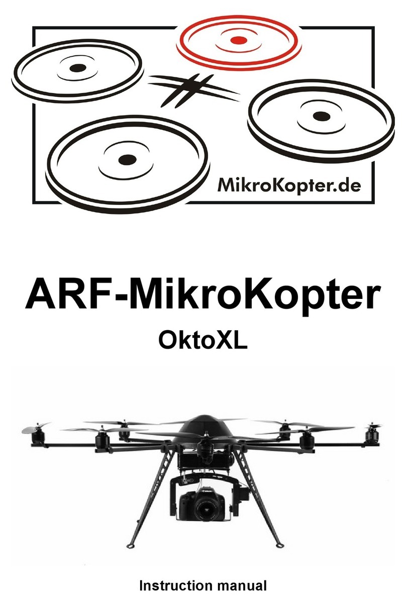
MikroKopter OktoXL User manual

ARF-MikroKopter
OktoXL + OktoXL 6S12
Instruction manual


Inde
Introduction....................................................................................................................................................................... 1
Symbols............................................................................................................................................................................ 1
Intended Use.................................................................................................................................................................... 1
Safety................................................................................................................................................................................ 2
General....................................................................................................................................................................... 2
Functions of the ARF MikroKo ter ................................................................................................................................... 3
Control........................................................................................................................................................................ 4
Before each flight........................................................................................................................................................ 5
Flight simulator................................................................................................................................................................. 6
Battery (LiPo) – General information................................................................................................................................7
Safety rules for LiPos.................................................................................................................................................. 7
Charging the LiPo ...................................................................................................................................................... 8
LiPo storage................................................................................................................................................................ 8
Using BID (Robbe)...................................................................................................................................................... 8
Overall View...................................................................................................................................................................... 9
ARF-MikroKo ter Connections....................................................................................................................................... 10
The bottom side........................................................................................................................................................ 10
Final Assembly ARF-OktoXL.......................................................................................................................................... 12
Mounting the battery holder......................................................................................................................................12
Assembly of the landing gear....................................................................................................................................14
Connecting the receiver............................................................................................................................................ 15
Final Assembly ARF-OktoXL 6S12.................................................................................................................................16
Mounting the battery holder......................................................................................................................................16
Assembly of the landing gear....................................................................................................................................18
Connecting the receiver............................................................................................................................................ 20
Pro eller assembly................................................................................................................................................... 21
Inserting the battery ................................................................................................................................................. 22
Checking the functions / First-time start.........................................................................................................................23
Channel assignment................................................................................................................................................. 23
First Test flight................................................................................................................................................................. 24
Settings for MikroKo ter Tool and Transmitter ............................................................................................................... 27
Parameterset / Settings............................................................................................................................................ 27
Ste 1: Setu MK-USB ........................................................................................................................................... 27
Ste 2: Connect MK-USB to the ARF-MikroKo ter ..................................................................................................28
Ste 3: Download MikroKo ter-Tool......................................................................................................................... 28
Ste 4: First Start MikroKo ter-Tool..........................................................................................................................28
Ste 5: Connect the battery .................................................................................................................................... 29
Ste 6: Checking the channel assignment................................................................................................................ 30
Ste 7: Testing the camera mount............................................................................................................................ 31
Ste 8: Camera trigger.............................................................................................................................................. 32
Ste 9: Test motors individually................................................................................................................................33
Ste 10: Test Gyrosco es......................................................................................................................................... 33
Calibration....................................................................................................................................................................... 34
Acceleration Sensor (ACC)....................................................................................................................................... 34
Gyrosco es (Gyros) ................................................................................................................................................. 35
Com ass................................................................................................................................................................... 35
Functions / Flight modes................................................................................................................................................. 37
The functions............................................................................................................................................................ 37
Free flight............................................................................................................................................................ 37
Altitude control..................................................................................................................................................... 37
GPS-Functions.................................................................................................................................................... 38
Teachable CareFree............................................................................................................................................ 39
FailSafe............................................................................................................................................................... 41
WayPoint Flight............................................................................................................................................................... 42
Acoustic signals – LED dis lays..................................................................................................................................... 44
Installation of the o tional accessories...........................................................................................................................45
Transmitter/Receiver MX-20 / MC-20 / MC-32 ........................................................................................................45
Transmitter assignment: Grau ner MX-20 ......................................................................................................... 46
Transmitter assignment: Grau ner MC-20 .........................................................................................................47
Transmitter assignment: Grau ner MC-32..........................................................................................................48

Mounting the camera mount.....................................................................................................................................49
Camera trigger - Shuttercable...................................................................................................................................50
Camera trigger – IR-Ctrl / LANC............................................................................................................................... 51
Installation of the video transmitter...........................................................................................................................52
Connection Bluetooth-Set / Wi.232-Set....................................................................................................................53
Ko ter-Pilot + CAM-O erator......................................................................................................................................... 54
Transmitter bind........................................................................................................................................................ 55
Choose Setting 5...................................................................................................................................................... 55
Maintenance................................................................................................................................................................... 56
Technical Data ARF-OktoXL........................................................................................................................................... 57
Technical Data ARF-OktoXL 6S12..................................................................................................................................59
Delivery .......................................................................................................................................................................... 61
License........................................................................................................................................................................... 62
Troubleshooting.............................................................................................................................................................. 64
Error Codes.................................................................................................................................................................... 65
Dis osal.......................................................................................................................................................................... 67
General..................................................................................................................................................................... 67
Batteries.................................................................................................................................................................... 67
Im ressum...................................................................................................................................................................... 67
Additional for a roval in Austria:................................................................................................................................... 68

Introduction
Dear Valued Customer,
thank you for urchasing our roduct..
This manual is art of the roduct. It will rovide you im ortant information regarding the o eration and handling. To
ensure a safe o eration lease read this instruction manual carefully before using.
Please kee this manual handy at all times as a reference!
All com any names and roducts are trademarks of their res ective owners. All rights reserved.
Symbols
This symbol alerts the reader to im ortant oints, such as hazards during o eration
and handling.
The "Info-Arrow" shows locations with additional ti s and hints.
Intended Use
The ARF-MikroKo ter is a model aircraft. An a ro riate liability insurance is mandatory for o eration. Please check your
insurance cover before using !
You as a user / ilot are res onsible for a safe o eration and correct function of the model !
The roduct is not a toy and it is not suitable for children under 14 years.
It is not allowed to make any unauthorized changes or modifications on the ARF-MikroKo ter.
O eration is allowed only with the ARF- MikroKo ter a roved modules, batteries and the original software.
Please follow all safety instructions in this manual. It contains im ortant information about using the
roduct.
HiSystems GmbH Page 1
!
info
info
!

Safety
General
The ARF-MikroKopter (ARF = Almost Ready to Fly) is a re-assembled, re-set and tested model aircraft.
Among those connections and/or adjustment work, a ro er execution must be ensured.
No liability will be assumed for damage caused by not following instructions in this manual. Im ro er
connection and adjustment will also void the warranty.
Normal wear, crash damage or consequential damage are also excluded from the warranty.
–Those at the ARF-MikroKo ter assembled motors can cause a noise during o eration and also
with an increased use.
–Those at the ARF-MikroKo ter used batteries will lose ower with an increased use.
–Plastic ro ellers can become brittle / fragile through time and by sun ex osure.
Please observe the following notes:
•The ilot must be able to fly the ARF MikroKo ter in any situation without aids, such as the GPS system.
•If you see a malfunction of the AltitudeControl or the GPS function, switch off the functions and fly the co ter
manually.
•Please note the information in the manual about your charger and transmitter.
•Do not switch off the transmitter while the co ter is ON and the ro ellers turn.
•Model aircrafts can cause significant ro erty damage and / or ersonal damage with im ro er handling.
•Do not touch a moving ro eller. This can cause severe injuries.
•Never catch the Ko ter out of the air! This may also lead to significant injury.
•Never turn the transmitter off during the flight. The Ko ter can crash and can cause considerable damage.
•Leave the transmitter switched on while the ARF-MikroKo ter is o erating.
•When starting, landing and flying make sure a sufficient large distance away from eo le, animals and objects
is ensured.
•Make sure the Ko ter can not take off unintentionally when making adjustments. If necessary remove the
ro ellers for your own safety (such as during an engine test).
•Do not ex ose the Ko ter to rain, moisture, excessive heat, cold or vibration.
•Do not control an ARF-MikroKo ter if you are under the influence of drugs or alcohol.
•Check the tightness of all connectors and screws as well as the mechanical integrity of the ARF-MikroKopter
before each start / flight.
•Never start if you have discovered a damage to the ARF-MikroKopter or to the transmitter / receiver.
•Fly with your ARF-MikroKopter always in sight. So you are able to res ond quickly if a fault occurs by external
influences.
Page 2 HiSystems GmbH
!
info
info

Functions of the ARF MikroKopter
The ARF MikroKo ter comes with the GPS-System. You can use many additional functions with this GPS-System.
Functions of the ARF-MikroKopter:
•Highly versatile. For exam le Photo / Video flight, action shots, ins ection / maintenance flights, surveys,
documentations, and much more.
•Easy to fly with automatic attitude stabilization (gyro and ACC su ort)
•Redundancy by 8 ro ellers
•Secure fly further and be able to land even if one engine / ro eller fails
•Fly securely at high wind strengths
•All functions are easy to use with the transmitter
•Safely carry ayloads of u to 2500g or >5.5 lbs (e.g. SLR camera, thermal imaging camera, etc.)
2500g => ARF-OktoXL / 4000g => ARF-OktoXL 6S12)
•Automatic alignment of a connected camera mount
•Additional control of the camera mount via the transmitter
•(Video-) Camera control and trigger via the transmitter
(o tionale Shutterkabel, IR-Ctrl oder LANC-Ctrl required)
•Start and Sto of a camcorder
(o tional IR-Ctrl or LANC-Ctrl required)
•Live view from camera on the ground
(o tional Videos transmitter/-receiver is needed)
•Automatic “AltitudeHold” during flight
•Automatic “PositionHold” during flight
•Automatic “ComingHome” to the start oint
•Automatic Start/Land
•Automatic „FailSafe“ if signal lost
•Automatic “BatterySafe”
(audible warning => Auto-ComingHome => AutoLanding)
•Wireless data transmission can be connected
•Dis lay of telemetry data with all im ortant data like battery ower, flight time, and more.
•See the current osition of the Ko ter in a ma (MikroKo ter-Tool on a La to required)
•Dis lay of telemetry data in the “OSD” of the MikroKo ter-Tool
•(o tional Wi.232 or Bluetooth and a La to required)
•Place u to 200 Way oints and/or POI ( oint of interest) on a ma
•Fly way oints and POI automatically
•Automatic alignment of a camera during a way oint flight
•Can follow a „FollowMe“ transmitter automatically
•and much more
HiSystems GmbH Page 3

Control
An ARF-MikroKopter is easy to fly. But it takes ractice and time to be able to control the Ko ter safely. The ilot must
also be able to fly the Ko ter in any situation without aids such as the GPS-System.
The Ko ter is controlled by a RC-transmitter. The Throttle, Yaw,
Roll and Nick functions can be controlled by the sticks.
•Throttle
◦Controls the s eed of the motors (u /down)
•Yaw
◦Turns the Ko ter around
•Nick
◦Flies forward or back
•Roll
◦Flies left or right
(Example: Mode2)
Ideally the ARF-MikroKo ter can stay on osition with no wind.
Info: Please leave the trim of the transmitter always in middle osition (off)
Via the switches, buttons and otentiometer of the transmitter further functions
like e.g. the automatic hold of the actual osition (PositionHold), an automatic
back-flight to the start oint (ComingHome) or non-directional flying (CareFree) can be used.
For this ur ose the mounted GPS-System and the com ass-sensor is used. The GPS system consists of the MK-GPS
and NaviCtrl. The com ass sensor is installed on the NaviCtrl.
The functions are further described in „Functions / Flight modes“ Page 37.
Page 4 HiSystems GmbH

Before each flight
Check the Ko ter always for:
•Damage to the frame, cables, motors, ro ellers and electronics
•Tightness of the rigger, motors and ro ellers
•Functions of the motors
•Tightness of all screws (Motors, Rigger etc.)
•Loaded and not damaged batteries (ARF-MikroKopter and transmitter)
•That the microSD card is insert into the NaviCtrl. (see age 62).
◦The SD card will safe the LOG file during flight. This can hel if you have a roblem with the co ter.
In the Settings the function „no start without SD ard“ is activated.
So if the SD-Card is not there or not lugged in correctly into the NaviCtrl, you can not start the Co ter.
In this case the Co ter will bee during you try to start the Co ter.
(See also „Maintenance“ Pg. 56)
The order of switching on / off the ARF-MikroKopter and the transmitter:
Switch on (before the flight):
1. All switches on the transmitter ut into the default „OFF“.
2. Switch on the RC-Control (if necessary choose the right model memory).
3. Bring the trim of the control-sticks into the middle osition.
4. Connect the ARF-MikroKopter to the battery (LiPo).
Switch off (after the flight):
1. Switch off the motors.
2. Disconnect battery (LiPo) from the ARF-MikroKopter.
3. Switch off the transmitter.
HiSystems GmbH Page 5
info
info

Flight simulator
To get familiar with the controls we recommend racticing with the AeroSIM RC – Flight simulator. In this PC-Program
various MikroKo ter models can be flown like in reality. The same transmitter can be used, which is later also used for
the control of the ARF-MikroKopter.
With different training rograms in this simulator your flying can be trained and im roved.
Page 6 HiSystems GmbH

Battery (LiPo) – General information
ARF-MikroKopters use Lithium-Polymer-Batteries, called LiPo. The ARF-MikroKopter is designed for the use with 4S
(14,8V) LiPos. The right LiPos can be urchased through us.
The ARF-MikroKopter monitors the battery during the flight. If the voltage gets low, a warning tone will sound from the
buzzer on the Ko ter.
This alarm is also signaled by an existing telemetry transmission on the transmitter (with the HoTT system) or PC (when
viewing in the MKTool OSD).
Once this alarm sounds, land immediately and load or change the LiPo..
Continuing the flight with a warning signal can ermanently damage the LiPo and the Ko ter could crash.
After landing the Co ter and turning off the motors the connection between LiPo and co ter should be se erated. Kee
the battery ack out of the ARF-MikroKo ter if that one is not used (e.g. storage or trans ort). That avoids a fully
discharge of the battery.
Do not charge the LiPo directly after landing. Let the LiPo always cool down. Im ro er handling of LiPos causes burns /
ex losion hazard! Do not use damaged or defective LiPos!
Before using the LiPo the first time it must be fully charged!
The first charge of LiPos, de ending on the charge level of the individual cells and o eration / erformance
of the charger been used, will take u to several hours.
The ro er charging and discharging of the cells / LiPos can not be monitored by us. Any warranty is
excluded for incorrect charging or discharging.
Safety rules for LiPos
Lithium-Polymer-batteries (LiPo) require articulary careful treatment. This a lies to charging, discharging, storage and
other handling. Incorrect usage / treatment of LiPos can cause erformance roblems, ex losion, fire, smoke, oisoning
and other roblems.
Do not cause short circuits as ermanent short circuits lead to the destruction of the battery. High tem eratures and
ossibly s ontaneous combustion can be the result !
Each charge / discharge and storage at too high / low tem eratures reduces the ca acity of the battery. The
recommended tem erature range for charging and storing LiPo - batteries is 0-50° C.
A battery is a wearing art. Please be aware that batteries will wear out with use, and flight time will decrease.
For charging LiPo batteries the a roved charger with the a ro riate charging cable must be used. The max. loading
ca acity must be limited to 1.05 times of the battery ca acity.
(Exam le: 5000mAh Akku = 5250mAh max. loading ca acity)
Use for charging and discharging of LiPo batteries only the es ecially designed charger / discharger.
The battery tem erature should not rise above 70°C during the discharge.
Make sure that the number of cells and the charge voltage are set correctly. A voltage above 4,25V er cell must be
avoided otherwise the cell will be damaged ermanently.
Further information about the settings get out of your instruction manual of your charger / discharger.
The battery which need to be charged must be while charging on a non-flammable, heat resistant and not conductive
surface ! Combustible or flammable materials need to be away from the charging s ot. Charge batteries only under
su ervision !
To store LiPos they should have a charge level of around 10-20%. During the storage the LiPos should be reviewed
regulary. This is easy with a LiPo-Tester. If the voltage of the cells go down to 3V they must be necessarely charged.
Dee -discharge and storage in discharged condition (cell voltage less than 3V) makes the battery useless..
The foil / outer shell of the LiPo can be easily damaged by shar objects such as needles, knives, nails, etc. If the foil is
damaged it makes the battery useless..
Mechanical shocks e.g. throughout dro ing, hitting, bending etc. can also make the LiPo unusuable.
Do not use damaged batteries under no circumstances ! Damaged or exhausted batteries are hazardous waste and
must be dis osed accordingly.
If a LiPo is damaged, avoid any direct contact with the electrolyte. By contact with the skin, eyes or other body arts you
HiSystems GmbH Page 7
info
info
!

need to clean or rinse it immediately with lenty of clean and fresh water. Then a doctor should be consulted.
Charging the LiPo
Only charge a LiPo with an a ro riate charger and integrated balancer.
The necessary settings can be found in the manual for the charger.
It is absolutely necessary that the recommendations in the instruction manual be followed.ger. After use the
LiPo should cool down before the next recharge.
The LiPo in the ARF-MikroKo ter consists of multi le internal cells. In addition to the cable with the Deans connector
another jack, the balancer, is connected with 5 cables to the LiPo. In that case the individual battery cells are monitored
during charging. With ro erly set values on the charger, charging the LiPo will be finished at a charge voltage of 4,22V
er cell.
The settings you need to charge a LiPo can be found in the manual of the charger.
Exam le: Connection to a Robbe POWERPEAK charger:
What does the inscri tion mean on the LiPo?
Exam le: 5000 / 14,8V / 4S1P / 20C / 4C Charge
5000 => Ca acity of the LiPo (here 5000mAh = 5Ah)
14,8V => Voltage 14,8Volt
4S1P => 4S = 4 cells are connected in series / 1P =
no further cell is connected arallel.
20C => Maximum current of the LiPo. This is
calculated as follows: (Ca acity/1000) x
Max. current (5000/1000) x 20 = 100A).
4C Charge => Maximum ermissible charging current.
A 5000mAh LiPo can be charged with
max. 20A (4x5000mA).
For a longer life LiPos should be charged only max. 1C.
LiPo storage
For the storage of a LiPo over a longer time eriod (e.g. over the winter months), he should not be quite fully charged.
Recommend is a single cell voltage of ~ 3.8 V. Fully charged LiPos can otherwise be damaged during long storage. The
LiPo should be checked at longer storage and, if necessary, be refueled.
Using B D (Robbe)
If a Robbe charger is used to charge the LiPos a BID-Chi can be
assigned to each LiPo. This BID chi stores all the relevant data for
charging the battery. When charging a LiPo, the corres onding BID-Chi is
connected to the charger. This gives the battery charger the necessary
battery arameter for s ecific LiPos.
Page 8 HiSystems GmbH
!
info
info

Overall View
1 – Protective hood
2 – Motor MK3638 / MK3644 with 12“ ro eller
3 – Rigger
4 – Landing gear „HiLander-26“
5 – Battery holder with LiPo
6 – Camera mount SLR2 (o tional)
7 – Additional camera (o tional)
8 – Video transmitter (o tional)
9 – Protective hood
10 – MKGPS
11 – GPS-Shield (im roves the GPS-receiving signal)
12 – NaviCtrl
13 – FlightCtrl
14 – Motor controller (BL-Ctrl)
HiSystems GmbH Page 9

ARF-MikroKopter Connections
As shown in the „Overall View“ (Pg.7) the ARF-MikroKopter is already equi ed with the FlightCtrl and the GPS-System
(NaviCtrl + MKGPS). The GPS has an additional GPS-Shield to get a better receiving signal of the GPS-Satellites.
All required connections can be found on the Flight- and NaviCtrl boards
Some connections are already assed out on the bottom-side of the ARF-MikroKopter.
The bottom side
At the ARF-MikroKopter the connection for the battery (LiPo), a PPM-Sum-signal receiver with telemetry connection, the
connection for the MK-USB (or Wi.232 / Bluetooth), the connection for the servos of a camera mount as well as the 2
su ly cables for the video transmitter are already rovided.
These cables are easily accessible on the bottom:
Page 10 HiSystems GmbH

Final Assembly
+
First Test Flight
HiSystems GmbH Page 11

Final Assembly ARF-OktoXL
First at all the landing gear, the battery holder, the ro ellers and a suitable receiver need to be assembled.
For the first start-up the propellers should not be mounted.
An assembly of the ro ellers can be done just before the first flight (see age 21).
For the assembly you need the following tools:
•Philli s screwdriver (Size PH1)
•Screwdriver
•Ring s anner (SW 8)
Mounting the battery holder
The battery holder is com osed of multi le com onents which can be
easily assembled.
First the narrow hook-ta e need to be threaded into the to late.
Im ortant: The soft side needs to face u wards.
The second self-adhesive hook-ta e need to be a lied to the lower late
as shown in the diagram.
Once this is done, the to and bottom late with the 9 Aluminium s acers,
4 rubber bum ers, 5 lastic screws and 9 lastic nuts can be assembled.
Page 12 HiSystems GmbH
info
info

The com letely assembled battery holder needs to be mounted on the bottom side of the ARF-MikroKopter. For this
ur ose the cover must be removed from the co ter. Now the battery holder can be fixed with the 4 su lied metal
screws (M3x16).
Attention: The o ening of the battery holder must oint to the LiPo cable.
(seen from above to the left)
The cover is mounted via 4 metal srews (3x10) to the frame.
HiSystems GmbH Page 13

Assembly of the landing gear
The landing gear "Hilander-26" can be mounted at any rigger. You can choose, if you want to mount 3, 4 or more landing
feet.
When using a camera, the front rigger #1 should not have a landing gear (it will block the view of the
camera).
The numbering of the riggers is in a clockwise direction beginning with the different colored front rigger.
E ample:
„ARF-MikroKopter“ with 8 rigger
=> Landing gear on rigger 2, 4, 6 and 8 (short riggers)
Assembly step 1 - 4:
Page 14 HiSystems GmbH
info
info

Connecting the receiver
One 3-line PPM cable and one1-wire data cable (for telemetry transmission) are used to connect the receiver.
(Those both cables come out on the back and the bottom side of the co ter.)
Here, e.g. a Grau ner GR-12/GR-16/GR-24, Jeti-RMK2 or a similar receiver with PPM sum signal can be connected
directly. The data cable for the telemetry transmission is lugged into the a ro riate ort of the receiver (if resent).
A telemetry transmission of the co ter to the transmitter is ossible with the Grau ner HoTT-System.
No other sensors are required.
An a ro riate mount for the GR-16 receiver is a lied to the ARF-MikroKopter. This will be hooked u with the receiver
to the back side of the battery holder.
You need to connect:
•the three-wire PPM-Connection PPM-Sum-signal
•the telemetry-cable to the telemetry in ut of the receiver (if available)
E ample installation with receiver GR-16:
In case that a different transmitter and receiver are used, the receiver must be bound to the transmitter and
set to the required sum-signal. Please refer to the manual of the transmitter how to activate the sum-signal
HiSystems GmbH Page 15
info
info
info
info

Final Assembly ARF-OktoXL 6S12
First at all the landing gear, the battery holder, the ro ellers and a suitable receiver need to be assembled.
For the first start-up the propellers should not be mounted.
An assembly of the ro ellers can be done just before the first flight (see age 21).
For the assembly you need the following tools:
•Philli s screwdriver (Size PH1)
•Screwdriver
•Ring s anner (SW 8)
Mounting the battery holder
The battery holder is com osed of multi le com onents which can be
easily assembled.
First the narrow hook-ta e need to be threaded into the to late.
Im ortant: The soft side needs to face u wards.
The second self-adhesive hook-ta e need to be a lied to the lower late
as shown in the diagram.
Once this is done, the to and bottom late with the 18 Aluminium
s acers, 4 rubber bum ers, 5 lastic screws and 9 lastic nuts can be
assembled.
Page 16 HiSystems GmbH
info
info
This manual suits for next models
1
Table of contents
Other MikroKopter Drone manuals
