M2.5x5mm
DOWN UP
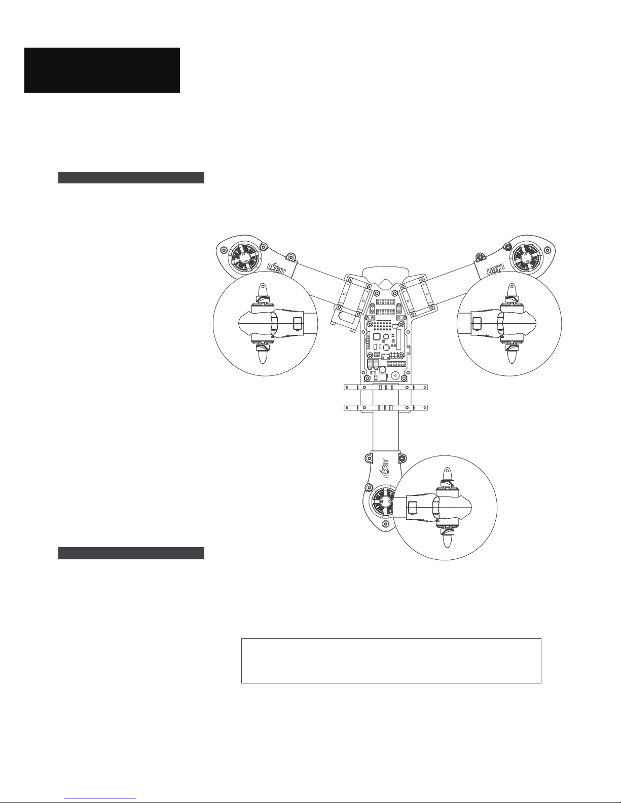
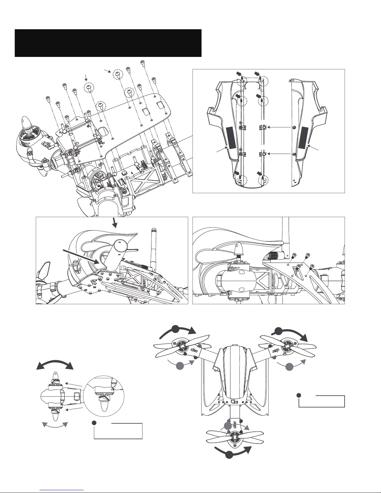
Place carbon arm in clamp as the picture shows.
Fix them with center bolts.
Clamp’s up and down.
Clamp installation position on carbon arm.
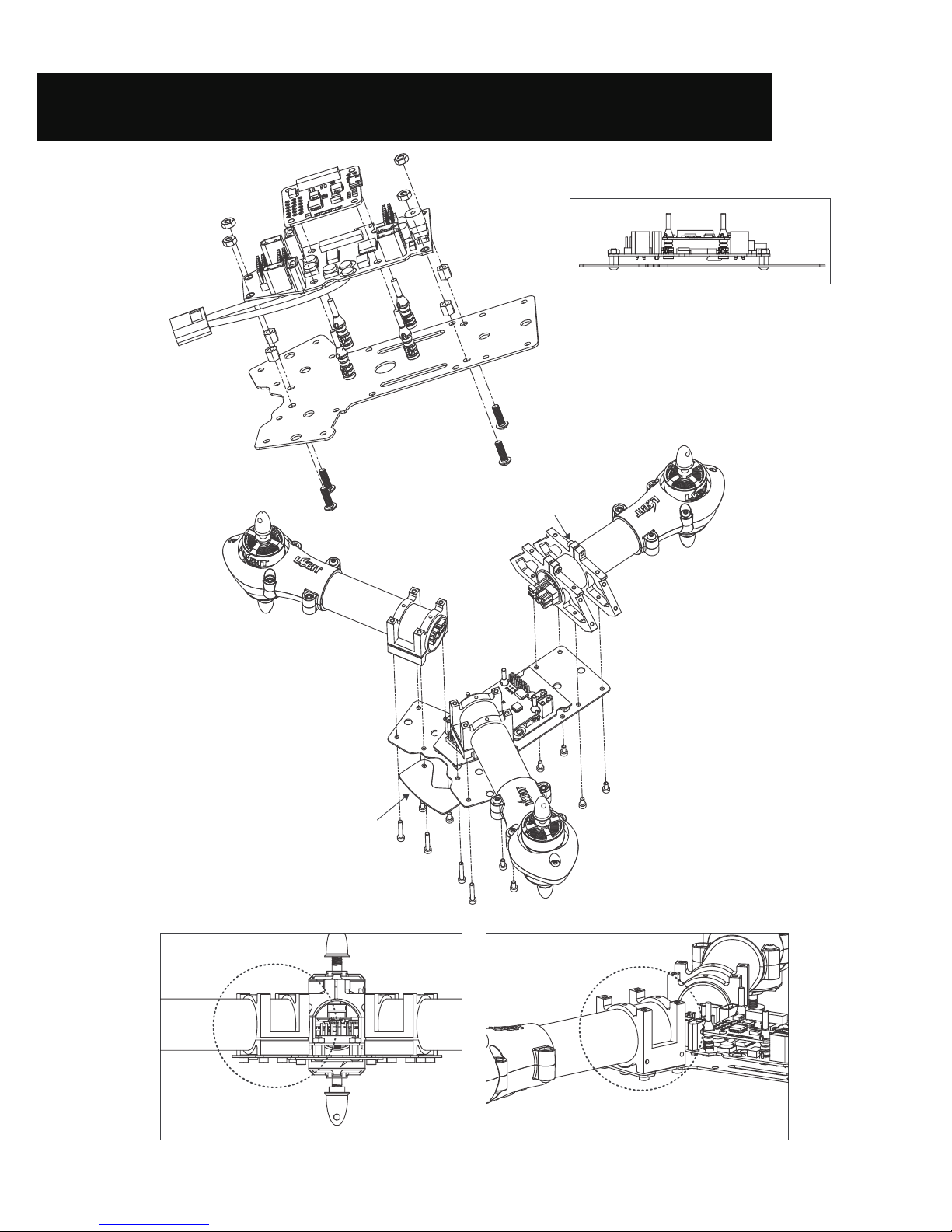
Arm Clamp Assembly
< >
Motor Arm & Camera Assembly
Prop Nut
Prop Washer
6x45 Prop
Propeller
Rotation Direction.
!
Motor
Rotation Direction.
!
!
M3x12mm
Hex Locknuts M3
Lobit Motor
2207 2200Kv Upper motor mount
Washers
M3x6mm
- Lower black mount: LOPL41
- Lower white mount: LOPL 40
- Upper black mount: LOPL41
- Upper white mount: LOPL40
Carbon Center Bolts
M2.5x5mm
ESC
Lower motor mount
Rubber dampers
LOAL41
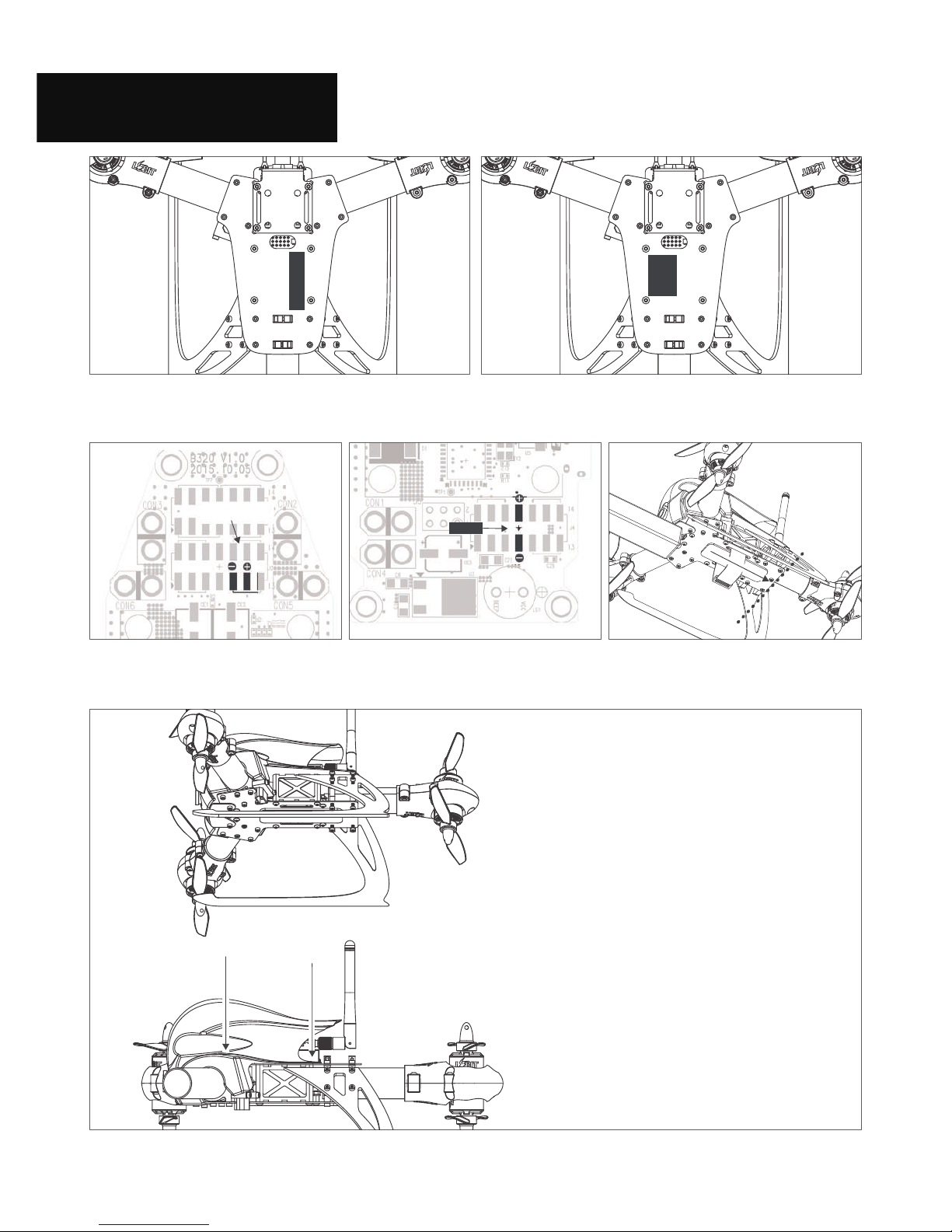
Camera Mount
LOAL41
Real Time View Camera Camera Bracket
LOAL41
320 Main Upper Panel
32CB41
Rubber dampers
LOAL41
Camera Bolts
Fixed Damper Position
35
4
3
Tier level
Tier level
Tier level
Tier level
Tier level
1
2
3
4
5
Assembly of two motors in front.
Top view
Bottom view
Small stud in each motor must be
put into a hole in carbon arm
Adjusting camera angle
by changing tier level.
Loosen camera bolts.
Then, tighten camera bolts again with camera bracket.
Five-tiered damper
< >
< >
Front, Rear Direction.
LOAL43
Arm Clamp
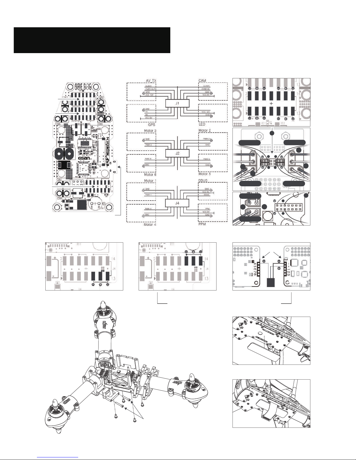
Connect 3 cables of motor to ESC.
Then, motor rotates.
You can reverse its direction of rotation
by swopping over any 2 of the 3 wires.
>
Motor ESC Cabling
<
- 3 -
- Front: 110mm 32CB43
- Rear: 97mm 32CB44
Carbon Arm


 user manual")