Aeronavics SkyJiB X4 XL Manual

1
Bu i l d M a n u a l

1.0 FLIGHT-OPS AND SAFETY
3Operation and Safety
5Pre-Flight Safety Check
6Do’s and Dont’s
2.0 PRE-BUILD CHECKLISTS
8Required Tools
3.0 ASSEMBLY INSTRUCTIONS
9Center Plate and Boom Assembly - Part 1
13 Coaxial Engine Mount Asssembly
17 Center Plate and Boom Assembly - Part 2
21 Standard Landing Gear
27 Retractable Landing Gear
30 Attach Landing Gear to Center Plate
32 Gear Rail Assembly
39 Crash Cage & Dome Assemblies
44 Quick Release Cams
2
Contents

This is a quick guide for those new to MultiRotor craft oering
some basic safety and operational procedures...and are
recommended standard operating procedures for those piloting
Aeronavics or any MultiRotor craft.
Please read the instructions for the relevant Flight Control
electronics before proceeding. Go to the website of your ight
control system and make yourself well acquainted with the
correct procedure for the electronics installation and software
operation.
Caution: never connect and start the engines for the rst
time with the propellers attached....and always balance your
propellers; unbalanced propellers can cause excessive vibration
which may lead to material fatigue.
Note: check the orientation of the ight controller you are
using (which way is front) and also the engine assignment
conguration; for instance which is engine 1,2,3 etc. and check
also that your propellers, clockwise and counter clockwise, are
also installed correctly before your rst ight.
Your rst test ight should be in an open eld in low or zero
wind. A sports eld (not currently in use) is a good option;
choose a site with short or mown grass. Do not takeo from
dry dusty sites. Make sure any onlookers or spectators do not
gather around you…if so ask them to move away from you in a
perimeter not less than 50m (150 feet) diameter around you.
Make sure that you have fully charged your transmitter and
onboard battery packs. Make sure that the antenna of your
Radio (TX) is up and correctly positioned; make sure the
receiver (RX) for your craft is well positioned within the craft and
secured and that the antenna is facing downward and to the
back of your craft and not touching any part of the craft.
Place the craft on level ground and turn on your transmitter –
check that you have the correct model selected on your TX.
Set the transmitter timer to about 80% of the known ight
duration. Connect the battery to your crafts FC inputs and wait
for the engine controller beeps to stop.
3
operation and s afety

Stand at least 5m away from your craft and behind the craft with
the craft facing directly away from you. Check the 50m ight
safety perimeter you have established, also checking behind you
for children running in to see what you are doing.
Survey the area; look for obstacles that you might not have seen
previously, like power-lines and overhead wires. Never y your
craft near a controlled aerodrome or in controlled airspace.
Check the weather conditions, the wind speed and direction.
Do not y in gusty strong wind at any time. Always try and y
the craft with the wind at your back so the craft will drift directly
away from you.
Always keep your eyes on the craft when in ight – if people
approach you inside your safety perimeter to talk to you or to
ask questions whilst you are ying the craft do not engage in the
conversation and ask them to stand well clear of you until you
have landed.
Re-check your perimeter and raise the throttle slowly and
check to see if the craft wants to tilt to one direction or another;
sometimes you may need to adjust the trim on your TX to get
a level ight, however most times the craft will y perfectly rst
time if you have installed the electronics and the software has
been set correctly—check with the Flight Control manufacturer
for standard or beginner settings for the craft.
Takeos are sometimes easier with a short burst of power to
lift the craft o the ground. Hold the craft in a controlled hover
directly in front of you about 2-3m o the ground away from
“ground eect” prop wash. When you have mastered this hover
position you can then move on to rolling the craft gently from
side to side and forward and backward.
Make sure that you always stand behind the craft, this makes
for easy orientation of the ight controls. Repeat this exercise
several times before you take the craft any higher.
Always y the craft well away from people and / or property.
Always check for children nearby.
4

Thoroughly check the craft before every ight…
• Check to see if any wires have come o
•Check for loose bolts on the assembly
•Check that the batteries are secure
•Check the battery voltage, and if you have more than one battery, check your spares too
•Check the propellers for marks and nicks
•Check the propeller nuts or bolts, make sure they are tight
•Check the engine mounts and the bolts and nuts for tightness
•Check the Transmitter battery voltage; never y the craft with a low voltage reading on your transmitter
(check with the manufacturer of your equipment for minimum and maximum voltage readings).
•Check that the transmitter antenna is not damaged.
•Check that the craft receiver module is well connected and that the antenna’s are properly positioned.
•Take a good look over the craft from all sides to make sure that nothing appears unusual or out of place.
•Check your ight perimeter.
•Check for power-lines and overhead obstacles.
•Assess the weather conditions, wind direction and speed. An anemometer (hand held wind speed meter) is a good tool
to have, otherwise use some dry grass or a tissue, throwing in the air to gauge the wind direction.
•Do not y in gusty and turbulent conditions.
•Set your transmitter timer to 80% of the known battery duration.
DISCLAIMER:
Aeronavics Limited disclaims all warranties, whether express or implied, including but not limited to the implied warranties of merchantability and tness for a particular purpose. Aeronavics Limited
does not assume any lyability, whether direct or indirect, from the use of Aeronavics craft. Aeronavics Limited shall not be liable for any direct, indirect, special, incidental, punitive, contingent or
consequential damages to persons or property caused by Aeronavics craft. In no event shall Aeronavics Limited be liable for personal injury up to and including death.
5
pr e - f light s afety C h e C k

•
Never y in strong wind – the operational safe wind speed for these craft is about 10-15 knots.
•
In the event of a crash or a hard landing, always check the craft for damage before taking o again. In this instance, you must also
check that you do not have dirt or grit in the engines; this can cause an engine or engines to overheat and fail in ight resulting in an
out of control craft and serious damage or injury to the craft , other people and their property.
•
Your launch eld should preferably be open and at with short grass. If it is necessary to take o in a eld which only has long grass,
manually atten a 1.5m diameter take o perimeter with your feet.
•
Always have a ight plan – visualize your ight path and check again for obstacles.
•
Never y the craft out of direct line of sight and always keep your eyes on the craft whilst it is in the air.
•
Never y the craft above 400 feet in height (the length of a football eld).
•
Never y near people – A 50m (150 ft) perimeter around and above people is a recommended minimum and operational law in
most countries.
•
Always set your transmitter timer before each ight to about 80% of the known ight duration for the battery pack’s you have installed in the craft.
•
Never turn your transmitter o in ight.
•
First person view ights are against the law in some countries – check the relevant aviation safety authority in your country before ying FPV.
Always have a “spotter” with you if you do y FPV.
•
Never let friends y your craft unless they are well schooled in the discipline.
•
Never y under the inuence of any substance or alcohol. Whilst there is a minimum blood alcohol level allowed for driving an
automobile in most countries, the law for pilots in command of ying craft around the globe is universal…there is a zero limit tolerance.
•
Always turn your transmitter on before connecting the battery to the craft...and always disconnect the battery from the craft before
turning your transmitter o.
6
do’sand d ont’s:

7
Pr e -B u i l d C h e C k l i s t

8
M4 3mm Hex Screw Driver
M4 Hex Driver
3mm Phillips Head Driver
M3 2.5mm Hex Screw Driver
re q u i r e d t o o l s
M3 Hex Driver

9
CENTER PLATE AND BOOM ASSEMBLY INSTRUCTIONS - Part 1
1
1
1
1
8
16
8
1
8
1
16
Center Plate Top 2.0mm SJ X4
Center Plate Bottom 2.0mm SJ X4
Universal FC Adaptor Plate
FC Adaptor Plate - DJI Wookong
Boom Bracket Inner
Gear Rail Center Plate Spacer
Stando Threaded
Decal Set SkyJib
Stando Threaded M3x12.7mm
Socket Head Cap Screw M4x40mm Ti
M4 Washer Stainless Steel
4
4
4
18
4
4
4
12
4
(1)
(1)
(1)
(1)
(1)
(2)
(1)
(1)
(1)
Socket Head Cap Screw M4x35mm
Socket Head Cap Screw M4x40mm s/s
Socket Head Cap Screw M4x35mm Ti
Machine Screw M3x6mm
Machine Screw M3x4mm
Stando Rubber Threaded
Nylon Nut M3
Locking Washer M4
Socket Head Cap Screw M4x40 Ti
Parts + SparesParts + Spares
2505-0110
2505-0120
2510-0160
2506-0140
2506-0480
2506-0230
2506-0180
2505-0200
2510-0100
Product Code Product Code
1205-0039
1205-0049
1206-0021
1206-0030
1205-0064
1505-0010
2503-0070
1205-0050
2506-0220
2510-0170
2510-0090

10
15
8
4
4
1
1
8
1
4
4
4
Standos Threaded M3x20mm M/F
Standos Threaded M3x20mm F/F
Nyloc Nut M4 Stainless Steel
Boom Bracket Outer 20mm
Wire Protector Plate SJ X4
Battery Strap
50mm Insulating Bush
Rubber Grommet 9.5mm
Assembled Quick Release Cam
Boom Folding Cam Nut 20mm
Boom Folding Cam 20mm
8
8
2
2
2
4
(1)
Socket Head Cap Screw M4x40mm
Boom Bracket Outer OD=20mm Black
Partially Assembled Q R Cams
Boom Folding Cam Nut 20mm
Boom Folding Cam 20mm
Socket Head Cap Screw M4x40mm Ti
Parts + SparesParts + Spares
2510-0170
1205-0084
1205-0210
1205-0200
2510-0170
Product Code Product Code
2503-0060
2503-0070
2505-0160
1205-0084
1205-0270
1406-0060
2506-0660
2503-0080
1205-0211
1205-0200
CENTER PLATE AND BOOM ASSEMBLY INSTRUCTIONS - Part 1
11
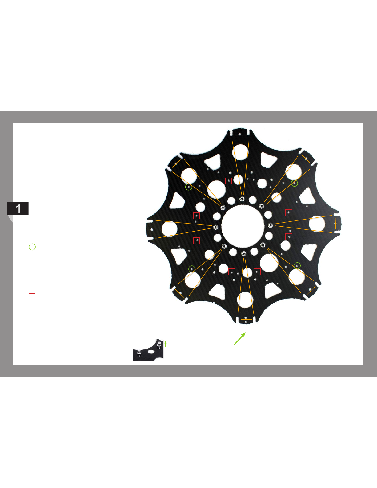
Rivnuts facing up
Take a moment to familiarise yourself
with the centre plate setup to get an
understanding which holes relate to
which parts. Take the top plate and
lay it out with the double hole at the
bottom and the notch to the left.
Circles show the holes used
for small dome xing.
Lines indicate the boom
mount triangle pattern used
for all models.
Droidworx Flight Control
Adaptor Plate
Front X4 XL

Turn the bottom plate upside down (rivnuts will be facing
up) and place the locking washer and at washers on to
the following screws as shown below. Push the M4x35mm
black Alloy Screws through the holes indicated with a green
circle below. Push the M4x35 Ti through the remaining holes.
Flip plate over and slot the Boom Bracket Inners onto the Ti
screws. Put Center Plate Spacers over the remaining black
screws. NOTE: For this model the
curve of boom brackets face
inward following the curvature
of the plate.
12
Place the remaining Boom Bracket Inners on top of the Booms
through the screws.
Lay the booms over the protruding screws as shown. You
will notice both ends have holes drilled.
Please ensure you use the holes that are closest to the
end of the boom. These holes are 11mm from the edge.
Flip the setup over, place the top centerplate on and fasten
the boom cluster screws. Be carefull that all brackets stay in
place.
TIP: Slide a piece of cardboard underneath to ip over.
OR: Instead of ipping the setup over you can slide each bolt
to the edge of your bench and tighten from underneath.

M3x8mm Screw
M4 Nyloc Nut
M3x6mm Button Head SCS
Heat Shrink Black
Engine Mount Shield Coax
Coax EM Shield Attachment
8
2
4
2
1
2
M4x35mm ‘Titanium’
Engine Mount Bracket M4 (50mm)
Engine Mount Disk M4 Coax
Threadlock (not included)
2
2
2
Parts + SparesParts + Spares
2510-0070
1205-0100
1205-0166
Product Code Product Code
2510-0240
2505-0160
2506-0070
2505-0010
1205-0172
1205 - 0180
13
COAXIAL ENGINE MOUNT ASSEMBLY

Apply the heat shrink to all engines. NOTE: Use treadlocking solution when putting in the screws.
Ax the engine to the engine mount disk by slotting the
desired machine screws through the chamfered side of the
disk and into the rewall mount holes of the engine.
(Repeat 8x)
x8
Press the Composite Brackets onto the Engine Mount
Disks. (8x)
x8
x4
Push the M4x35mm Titanium SHC Screws
through the holes either side of one of the
disks for each coaxial assembly. (4x in total)
14
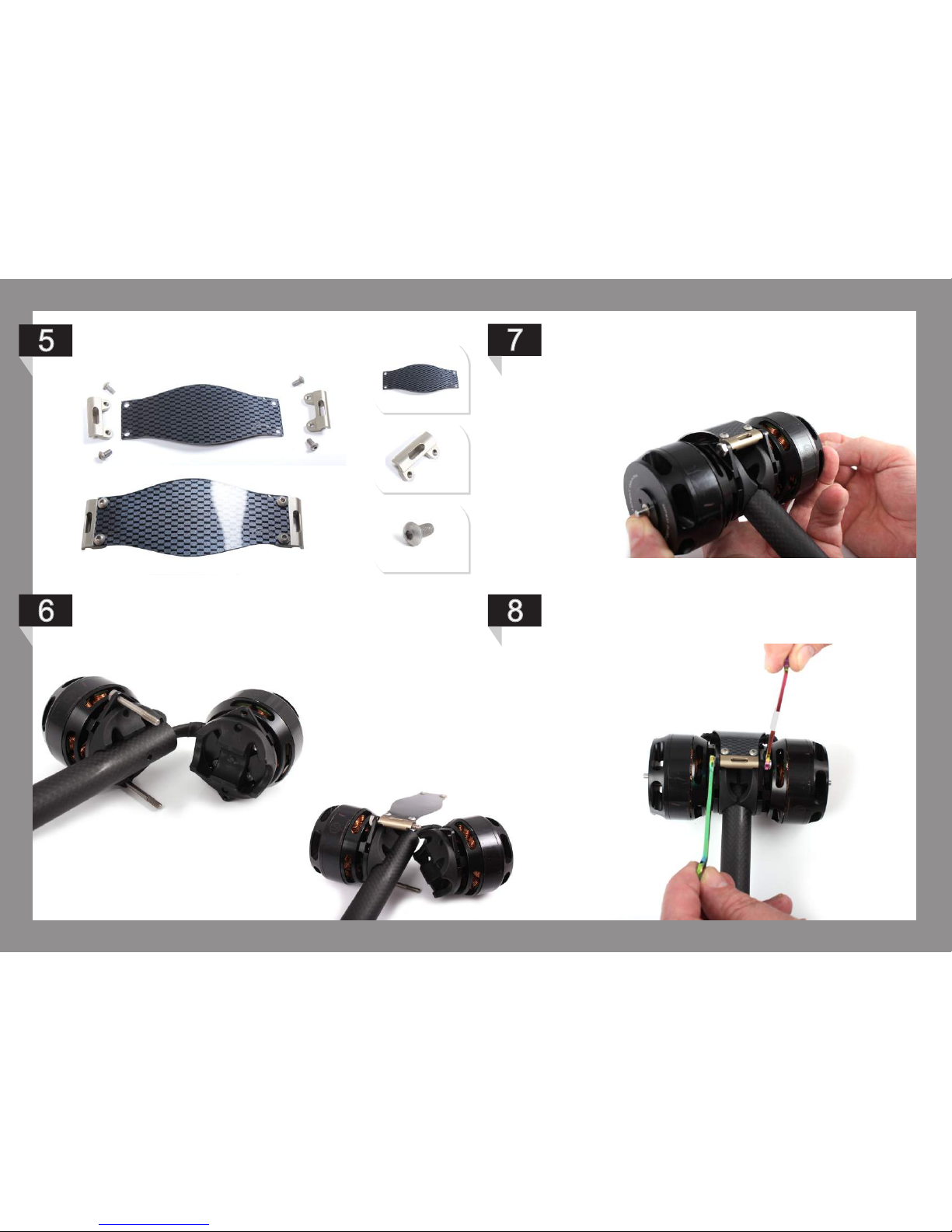
Feed your engine wires through the boom then ex your shield
and slide it over the M4x35mm Titanium SHC Screws.
Place your Boom onto the Engine Mount Bracket
making sure the tab locks into the hole of the boom.
Add the second Engine assembly.
Ax with the M4 Nyloc Nut SS. Repeat these steps for all
the engine assemblies.
Assemble the Engine Mount Shield as shown below.
x2
x4
15

Your nal setup should now look like this.
16

Insert M3x6mm Nylon Screws into the stand o holes in your
Center Plate using either your hands or attach a little bit of Blu-
Tak on your tool. Then wind the Stando M3x20mm onto the
screw. (Repeat 8x)
Insertthe4rubbergrommetsintothegrommet-holesintheWire
Protector Plate. Then insert the 50mm insulating bush into the
Wire Protector Plate. Your assembly should now look like this:
x4
17
Sit the completed plate over the vertical facing rivnuts on the
top SkyJib centre plate with the bulk of the insulating bush
facing down into the core of the craft.
Attach a Power Hungry Power Distributer together using
M3x10mm M/F standos and Nylon nuts then attach the
Universal Flight Controller Adapter Plate to the distributer
using 10mm rubber standos as shown below.
CENTER PLATE AND BOOM ASSEMBLY INSTRUCTIONS - Part 2

Place the ESC mounting plate on to the standos and x
with 20mm F/F nylon standos.
NOTE: You should now mount your ESCs to this plate.
18
Place your Power Distribution assembly
on top of the standos and x with
M3x6mm nylon screws.
NOTE: You should now plug your
engine wires into the distributor.
Next place your Wookong adaptor plate on to the rubber
standos and x with the M3x6mm nylon screws as shown
below.

Your assembly should now look like this:
19

Push the M4x40mm Ti screw through the center plates and
spacer and x with M4 nyloc nut s/s as shown below. Repeat
this step on the other side.
Your assembly should now look like this.
20
Other Aeronavics Drone manuals


