Milky AR 140 E User manual
1
de BETRIEBSANLEITUNG
OPERATING INSTRUCTION
NOTICE D’UTILISATION
en
fr
MILCHZENTRIFUGE AR 140 E
CREAM SEPARATOR AR 140 E
CENTRIFUGEUSE À LAIT AR 140 E
230 V - Type 17593-E
115 V - Type 17593-115-E
JANSCHITZ GmbH |Eisenstraße 81 | A-9330 Althofen
T: +43 4262-2251-0 | F: +43 4262-2251-13

de INHALTSVERZEICHNIS
Allgemeine Sicherheitsempfehlungen
Technische Daten
Auspacken und Einrichten
Zubehör, Ersatzteile
Montage des Gerätes
Zusammenbau der Trommel
Entrahmen
Einstellung der Rahmmenge
Reinigung der MZF*
Reinigung der Trommel
Teilliste + Aufbau /Detailzeichnung MZF*
Teilliste Trommel
Ersatzteilbestellung
Garantie
Seite
3
4
4
4
5
6
6
7
7
8
9
10
11
11
Lieber Käufer!
Wir sind überzeugt, dass Sie mit unserer Milchzentrifuge zufrieden sind und, dass
sie Ihnen noch lange bei der Arbeit hilft. Wir hoffen, dass Sie unsere Milchzentrifuge
auch Ihren Freunden und Verwandten weiterempfehlen werden.
Danke für Ihr Vertrauen! Stand: Dezember 2018
* Milchzentrifuge

3
ALLGEMEINE SICHERHEITSEMPFEHLUNGEN
VOR DEM ERSTEN GEBRAUCH DIESES GERÄTES DIESE ANWEISUNG SORG-
FÄLTIG DURCHLESEN.
BITTE ACHTEN SIE, DASS VOR JEDER ANWENDUNG DIE TROMMELMUTTER
FESTGEZOGEN IST.
VOR DER REINIGUNG DES UNTERGESTELLS IMMER DEN STECKER DES GERÄTES
AUS DER STECKDOSE ZIEHEN.
REPARATUREN ODER SONSTIGE EINGRIFFE, DIE SICH NICHT AUF NORMALEN
SERVICE DES GERÄTES BEZIEHEN, DÜRFEN AUSSCHLIESSLICH NUR VOM AUTO-
RISIERTEN KUNDENDIENST VORGENOMMEN WERDEN.
WENN BEIM BETRIEB STÖRUNGEN AUFTAUCHEN, TRENNEN SIE DAS GERÄT
VOM NETZ UND WENDEN SIE SICH AN DEN AUTORISIERTEN KUNDENDIENST.
SCHÜTZEN SIE DAS GERÄT VOR FEUCHTIGKEIT UND WASSER.
WENN DAS GERÄT NICHT RICHTIG FUNKTIONIERT, OBWOHL SIE ALLE AN-
WEISUNGEN GENAU BEACHTEN HABEN, DÜRFEN SIE NUR DIE ANWEISUNGEN
UND VORGÄNGE DURCHFÜHREN, DIE IN DIESER GEBRAUCHSANWEISUNG BE-
SCHRIEBEN SIND. ALLE ANDEREN VORGÄNGE ODER ANPASSUNGEN KÖNNEN
SCHADEN AM GERÄT ODER LÄNGERE REPARATURZEITEN VERURSACHEN. WIR
ÜBERNEHMEN KEINE VERANTWORTUNG FÜR ALLE SCHÄDEN AN PERSONEN
ODER GERÄTETEILEN, DIE DURCH FALSCHE VORGÄNGE ODER HANDHABUNG
VERURSACHT WERDEN

4
Item Milchzentrifuge AR 140 E
Spannung (Model 230 V) (V/Hz) 230/50
Spannung (Model 115 V) (V/Hz) 115/60
Leistungsaufnahme (W) 70
Max. Geschwindigkeit (1/min) 9500
Kapazität (l/h) 140
Kapazität des Gefäßes (l) 12
Empfohlene Menge eines Zyklus (l) bis 60
Teller mit Buckeln mittig (Stk.) 11
Teller mit Buckel versetzt (Stk.) 10
Nettogewicht (kg) 3,50
Schutzklasse (IP) 23
TECHNISCHE DATEN
Das empfohlene Fassungsvermögen zur Entrahmung ist das maximale Milchvolumen,
dass während eines Entrahmungsvorganges entrahmt werden kann. Es hängt auch davon
ab, wie viele feste Teile bzw. Schwebstoffe in der zu entrahmenden Milch enthalten sind.
Wenn der Fluss der entrahmten Milch etwas langsamer wird müssen die Trommel und die
Teller gereinigt und etwaige weiter Verschmutzungen beseitigt werden.
AUSPACKEN
Öffnen Sie den Karton vorsichtig.
Entnehmen Sie das Styropor aus dem Karton. Öffnen Sie den Styroporoberteil und ent-
nehmen Sie Motorteil und Milchbehälter mit den Einzelteilen aus der Verpackung.
Stellen Sie das Gerät auf eine feste Fläche in einen trockenen und sauberen Raum auf.
Es wird empfohlen die Milchzentrifuge auf der Oberfläche zu fixieren. Verwenden Sie dazu
Schrauben.
WERKZEUGE, ZUBEHÖR UND ERSATZTEILE
Zu jeder Maschine werden folgende Teile mitgeliefert:
• Gebrauchsanweisung
• Rahmschraubenschlüssel mit Trommelschlüssel 3712069
Bitte beachten Sie!
Verwenden Sie NIE eine Milchzentrifuge mit beschädigtem Netzkabel!
5
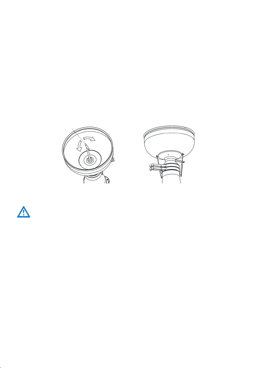
ZUSAMMENBAU DES GERÄTES
1. Unterteil auf einen Tisch oder ähnliche Unterlage stellen..
2. Zusammenmontierte Trommel auf die Kunststoffwelle/Konus mit leichten
Druck aufsetzen.
3. Magermilchauslauf auf das Unterteil setzen. Rahmauslauf auf Magermilchauslauf
setzen.
4.
Durch kurzes Drehen an der Trommel prüfen, ob diese nicht an den beiden
Ausläufen streift.
5. Einlaufgefäß auf den Rahmauslauf aufsetzen. Schwimmer einlegen und Vollmilchgefäß
aufsetzen (siehe untenstehendes Bild).
6.
Milchhahn einstecken. Den Milchhahn so drehen, dass der dünne Teil nicht auf die
Einkerbung am Außenrand des Vollmilchgefäßes zeigt. Der Milchausfluss ist geschlossen.
WENN SIE DAS VOLLMILCHGEFÄSS FÜLLEN MUSS DER MILCHHAHN GESCHLOS-
SEN SEIN! DER DÜNNE TEIL DES MILCHHAHNS DARF NICHT AUF DIE EINKER-
BUNG AM AUSSENRAND DES VOLLMILCHGEFÄSSES ZEIGEN!
Gummifixierhaken sind nur bei FJ 130 vorhanden.
6
ENTRAHMEN
Am besten gleich nach dem Melken entrahmen. Ist das nicht möglich, erwärmt man die
Milch auf 30-35°C. Beim Zentrifugieren unter dieser Temperatur leidet die Entrahmungs-
schärfe. Wenn die Milch die richtige Temperatur hat, gießen Sie sie in das Vollmilchgefäß.
• Zentrifuge mit I / 0 Schalter einschalten. Etwa 30 Sekunden warten, bis die Trommel die
volle Drehzahl erreicht hat.
• Nur dann können Sie den Milchhahn öffnen.
Dabei muss die dünne Seite in Richtung der Einkerbung zeigen. Diese ist am Außenrand
des Vollmilchgefäßes sichtbar. So wird der Durchfluss geöffnet. Eine Kaltentrahmung ist
nicht möglich.
Wenn Milch aus dem Loch des Gehäuses rinnt, bedeutet dies:
• Milchhahn war geöffnet, obwohl die Trommel noch nicht die volle Drehzahl erreicht hat.
• Trommelmutter war nicht ausreichend fest angezogen.
• Gummiring ist nicht richtig eingelegt oder er ist defekt.
In solchen Fällen schließen Sie den Milchhahn, schalten den Motor aus und beseitigen den
Fehler.
VOR JEDER INBETRIEBNAHME DES GERÄTES MUSS DIE TROMMEL UND DESSEN
TELLER SAUBER GEREINIGT WERDEN UND TROCKEN SEIN
ZUSAMMENBAU DER TROMMEL
1. Gummiring/Dichtungsring in das Trommelunterteil richtig einlegen.
2. Die Teller sind in zwei verschiedenen Formen vorhanden – Teller mit
Buckel mittig und Teller mit Buckeln versetzt.
Die Teller abwechselnd einsetzen. Keine Kraft anwenden. Teller kommen
durch leichtes Verdrehen in die richtige Position.
3. Schneideteller mit Rahmschraube aufsetzen.
4. Den Trommeldeckel aufstecken. Die Aussparung muss in den Schneidetel-
ler passen
5. Trommelmutter mit der Hand einschrauben und leicht festziehen. Mit dem
Trommel- und Rahmschlüssel die Trommelmutter nun genügend fest an-
ziehen. Es ist wichtig, dass auf einen festen Sitz der Trommelmutter geachtet
wird. Diese ist der größten Belastung ausgesetzt.
3 Trommelteller relief- Buckel versetzt
4 Trommelteller – Buckel mittig
7
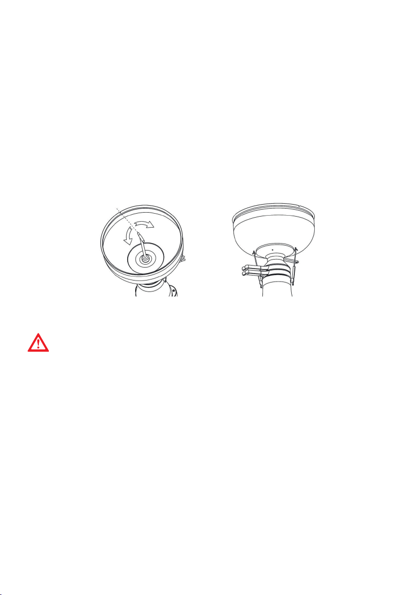
EINSTELLUNG DER RAHMMENGE
Die Milchzentrifuge ist so eingestellt, dass die Trommel bei einer Milchtemperatur von 35°C
etwa 8-12% der gesamten Vollmilch als Rahm ausscheidet. Wird eine andere Rahmmenge
gewünscht, so ist die Rahmschraube mit dem Sechskant des Trommelschlüssels zu verstel-
len.
• Wird dicker Rahm, d.h. weniger Rahm gewünscht, so drehe man die Rahmschraube nach
rechts (im Uhrzeigersinn).
• Wird dünner Rahm, d.h. mehr Rahm gefordert, dann dreht man die Schraube nach links
(gegen den Uhrzeigersinn). In den meisten Fällen genügt eine Viertelumdrehung.
ACHTEN SIE DARAUF, DASS DIE RAHMSCHRAUBE NICHT ZU STARK FESTGEZO-
GEN WIRD, DA DABEI DAS GEWINDE BESCHÄDIGT WERDEN KÖNNTE. WENN DIE
RAHM-REGULIERSCHRAUBE ZU SEHR ZURÜCKGEDREHT/HERAUSGEDREHT WIRD,
KANN DER OBERE TEIL DER TROMMEL NICHT HERUNTERGENOMMEN WERDEN.
WICHTIG! Wenn Sie die Milch schon entrahmt und den Motor ausgeschalten
haben, ist es Ihnen nicht gestattet den Motor wieder einzuschalten, solange nicht
die Restmilch aus der Trommel entfernt wurde. Nach Beendigung der Entrahmung
gießen Sie ca. ½ Liter entrahmte Milch nach, damit die Rahmreste aus der Trommel
entfernt werden. Schalten Sie danach den Motor aus und reinigen und trocknen Sie
die Trommel und Teller sorgfältig.
- Kleineres Rahmvolumen höheres Rahmdichte
+ Höheres Rahmvolumen kleineres Rahmdichte
REINIGUNG DER MILCHZENTRIFUGE
• Alle Teile der Trommel können in heißem Wasser unter Zugabe von fettlöslichen Reini-
gungsmitteln gesäubert werden.
• Milch- und Schmutzreste sind mit einer Bürste oder einem weichen Tuch zu entfernen.
Man achte darauf, dass sämtliche Löcher in den Trommelteilen sauber sind, insbesonde-
re das Loch in der Rahmschraube, die Einlauftülle im Einlaufgefäß und die mitgelieferte
Reinigungsbürste. Andere Teile die mit der Milch in Kontakt kommen, können mit warmen
Wasser unter Zugabe von Reinigungsmitteln gereinigt werden. Danach spült man die Teile
mit klarem Wasser aus.
• Trockene Milch und Rahmreste sollen von der Milchzentrifuge nicht mit scharfen Gegen-
ständen, beziehungsweise mit einem groben Tuch entfernt werden. Dabei könnte die
Oberfläche der Plastikteile, beziehungsweise die eloxierte Oberfläche der Aluminiumteile
beschädigt werden.
• Bei Reinigung des Untergestells den Stecker aus der Steckdose ziehen! Die Milchzentri-
fuge zuerst mit einem feuchten Tuch abwischen und danach trocknen. Achten Sie darauf,
dass die Feuchtigkeit nicht in das Gehäuse eindringt.
Vergewissern Sie sich, dass weder der Motor noch andere elektrische Teile mit Wasser
in Berührung kommen. Es dürfen keine Flüssigkeiten in den Motorraum eindringen.
8
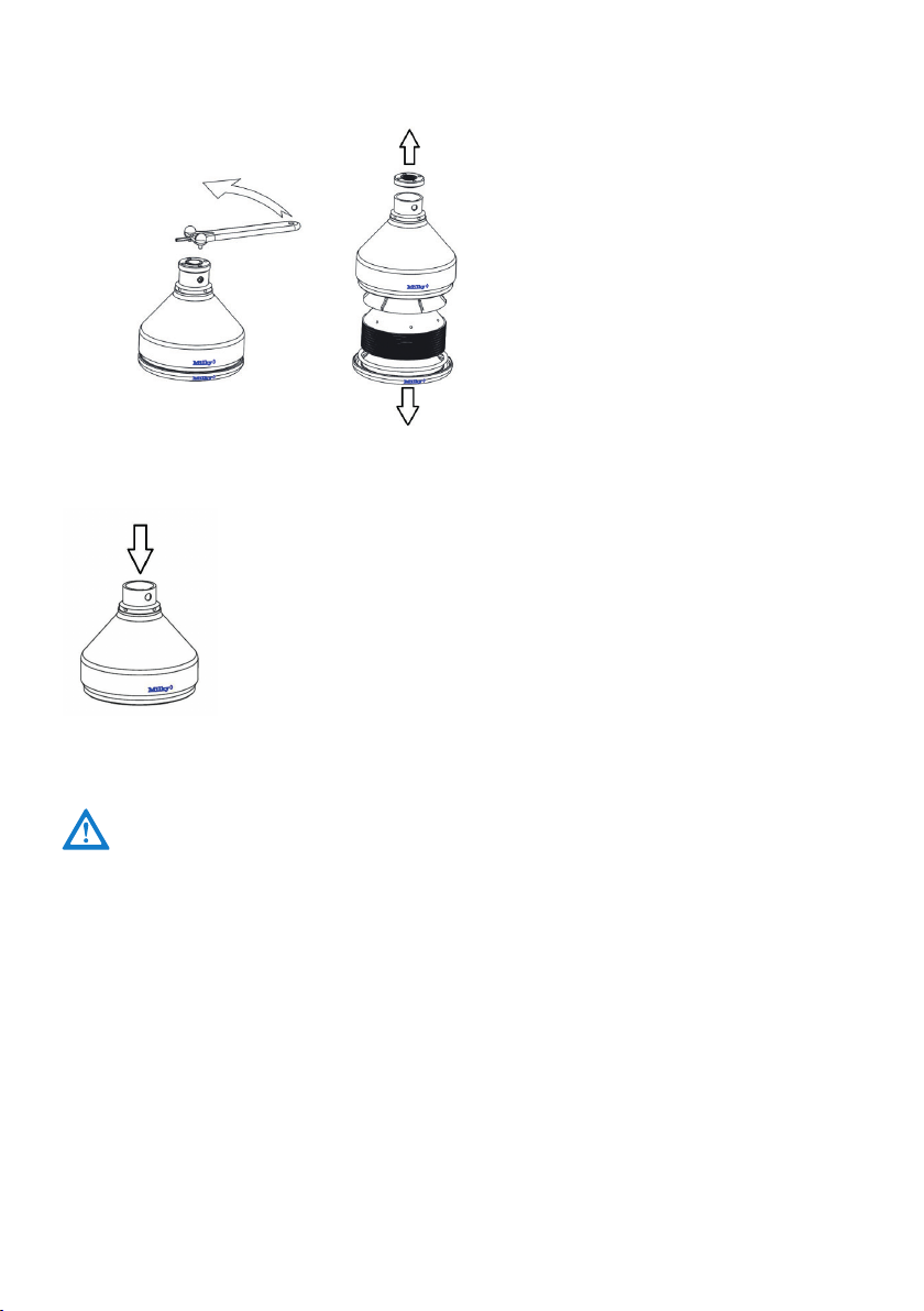
WENN SIE DIE TROMMEL NICHT VOM MOTORSCHAFT/KONUS TRENNEN KÖN-
NEN, RÜTTELN SIE DARAN EIN WENIG. SIE DÜRFEN DABEI KEINE KRAFT AUF-
WENDEN – DIES KÖNNTE DIVERSE TEILE DES GERÄTES BESCHÄDIGEN!
REINIGUNG DER TROMMEL
Laut Skizze mit dem Rahmschraubenschlüssel die Trommelmutter abschrauben.
Die Trommel wird wie folgt auseinandergenommen:
1. setzen Sie den Schlüssel in die Löcher der Trommelmutter ein.
2. Die Mutter wird mit dem Trommelschlüssel gelöst. Das völlige Lösen
der Trommelmutter kann mit der Hand erfolgen. Die Trommel öffnet
sich nun ohne Schwierigkeiten.
3. Nach dem Öffnen der Trommel entnehmen Sie Sie das Scheideteller
und die Teller. Entnehmen Sie auch den Gummiring. Reinigen Sie die
Teile vorsichtig. Ein dehnen des Gummiringes muss vermieden werden.
Reinigen Sie die Teile mit heißem Wasser unter Zugabe von Reinigungs-
mitteln.
4. Alle Teile mit warmen Wasser nachspülen und komplett trocknen.
5. Waschen Sie die Teile unter keinen Umständen im Geschirrspüler!
9
TEILLISTE
Bezeichnung Art.-Nr.
1Fuß 3711019
2 Bodenplatte 3171017
3 Motor 230 V 17595
4 Motor 115 V 17596
5 Ein / Aus Schalter 371151
6 Gehäuse - blau 37005B
7 Kabel komplett 230 V 26002
9 Kabel komplett 115 V 26003
10 Motorgummidichtung 3711013
11 Trommel komplett 375021K
12 Magermilchauslauf 3711037
13 Rahmauslauf 3711039
14 Einlaufgefäß - ALU 3711041
15 Schwimmer Plastik 3752045
16 Vollmilchgefäß Alu 370000
17 Milchhahn 3711061
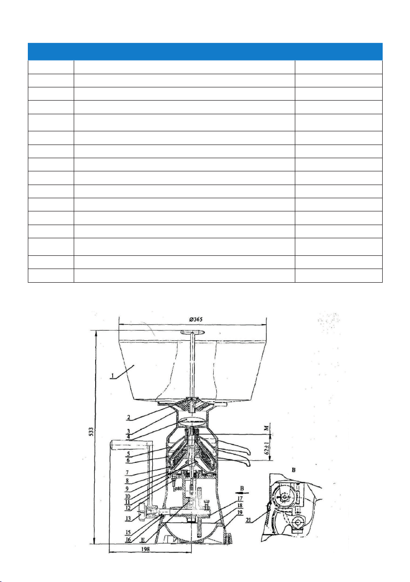
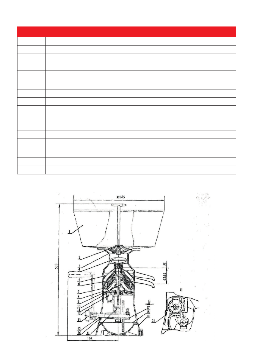
AUFBAU DER MILCHZENTRIFUGE
10
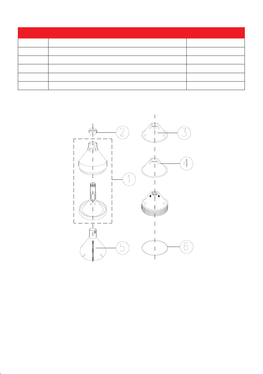
Teileliste der Trommel
Ersatzteil
Art. No.:
1.
Trommelunterteil
Trommeldeckel
Trommelmutter
SE 404930
2.
TRommelmutter
SE 403202
3
Trommelteller 1
SE 403203
4
Trommelteller 2
SE 403503
5
Schneideteller
SE 404203
6
Gummiring
SE 102679
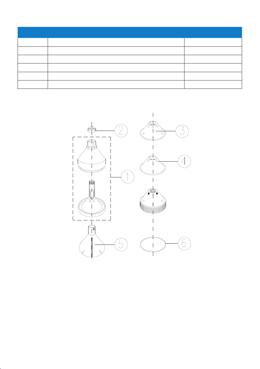
TEILLISTE TROMMEL
Bezeichnung Art.-Nr.
1 Gummidichtung 3711033
2 Trommelteller relief 3711025
3 Trommelteller - glatt 3711026
4 Schneideteller 3711029
5 Trommelschlüssel 3712069
6 Rahmschraube 103444

11
Änderungen und Druckfehler vorbehalten.
ERSATZTEILBESTELLUNG
Eine schnelle und richtige Lieferung von Ersatzteilen ist nur möglich, wenn Sie uns
folgende Daten mitteilen:
• Typ der Milchzentrifuge.
• Seriennummer des Gerätes, die auf dem Typenschild am hinteren Teil des Gehäuses ist.
• Ersatzteilbenennung und Nummer. Die Daten finden Sie in der Teileliste.
GARANTIE
1. Wenn Sie Probleme haben, wenden Sie sich an den Verkäufer oder an unseren Service.
2. Ein Garantieanspruch besteht nur bei Mängeln, die nachweislich auf Fabrikations – oder
Materialfehler beruhen. Die Garantiezeit beträgt 12 Monate. Unsere Verpflichtung bei der
Garantie beschränkt sich nur auf eine Reparatur oder Austausch des Gerätes oder seiner Teile
(aufgrund unserer Beurteilung) in einer Zeit von 12 Monaten nach dem Kauf.
3. Mängel oder Störungen der Milchzentrifuge, die auf unsachgemäße Montage, Bedienung,
Anschluss oder Behandlung zurückzuführen sind, sind von der Garantie ausgeschlossen.
4. Von der Garantie ausgeschlossen sind:
a. Ein durch Wasser oder Milch zerstörter Motor,
b. Anschlussleitung.
5. Die angegebenen Daten gelten nur dann, wenn alle Vorbedingungen in der Gebrauchsan-
weisung erfüllt sind.
6. Ansprüche jeder Art, die über die vorgenannten Verpflichtungen hinausgehen, insbeson-
dere Schadenersatzansprüche, sind ausgeschlossen.

12
en CONTENT
General safety recommendations
Technical Specifications
Unpacking and Set Up
Accessories
Assembling Procedure
Top Bowl assembling Procedure
Skimming Procedure
Skimming Regulation
Maintenance and Cleaning
Top Bowl cleaning procedure
List of composing parts
List if composing parts top bowl
Spare parts ordering Procedure
Warranty
Page
13
14
14
14
15
16
16
17
17
18
19
20
21
21
Dear Customer!
We are happy, that you have chosen Milky. We hope, that our device will serve you
as a helpful tool for a long time without any problems. We would be happy, if you
could recommend us to your friends.
Version: December 2018

1313
GENERAL SAFETY RECOMMENDATIONS
BEFORE ANY INSTALLATION, READ THIS MANUAL VERY CAREFULLY.
MAKE SURE, THAT YOU HAVE CLOSED TOP BOWL FIXING NUT TIGHTLY.
DISCONNECT DEVICE FROM MAINS BEFORE CLEANING.
DON’T REPAIR THE DEVICE BY YOURSELF, IN CASE OF MALFUNCTION RATHER
CALL AUTHORIZED SERVICE PROVIDED BY YOUR DISTRIBUTOR.
TAKE CARE THAT WATER OR HUMIDITY WILL NOT COME INTO THE DEVICE,
ESPECIALLY BY CLEANING PROCEDURES.
IN CASE OF SERIOUS MALFUNCTIONS, UNPLUG THE DEVICE FROM MAINS AND
CALL AUTHORIZED SERVICE.
IN CASE, THAT THE DEVICE IS NOT FUNCTIONING PROPERLY, EVEN YOU HAVE
EXACTLY FOLLOWED INSTRUCTIONS DESCRIBED IN THIS MANUAL, YOU ARE
ALLOWED TO USE ONLY THOSE PROCEDURES, WHICH ARE ALLOWED BY THE
USER MANUAL. USE OF ANY OTHER PROCEDURES OR ADJUSTMENTS COULD
RESULT IN DEVICE DESTRUCTION OR LONGER SERVICE TIME. INJURIES CON-
NECTED WITH SUCH PROCEDURES CANNOT BE MATTER OF ANY PRODUCT
LIABILITY CLAIMS.

14
Item Cream Separator AR 140 E
Operating Voltage (Model 230 V) (V/Hz) 230/50
Operating Voltage (Model 115 V) (V/Hz) 115/60
Motor Power (W) 70
Max. Rotating speed (1/min) 9500
Max. Capacity (l/h) 140
Max. Container Capacity (l) 12
Recommended capacity for skimming (l) to 60
Relief Discs (Pcs.) 11
Plain Discs (Pcs.) 10
Net weight (kg) 3,50
Protection class IP 23
TECHNISCHE DATEN
Recommended skimming capacity is volume of the milk that can be skimmed within one
skimming cycle. It depends how much solid parts are in the milk. If the flow of the skim-
med milk is reduced than the discs and the bowl must be cleaned.
UNPACKING AND SET UP
Take the device out of the cardboard box and remove packing inserts. Place it on the plain
and stable surface in clear and dry place. Fixing the device on the surface is recommen-
ded. If you want to fix it on the surface, take the screws and fix it on the surface.
ACCESSORIES
In each package you will find also following accessories:
• Operating Manual
• Key for bowl fixing nut and cream screw 3712069
Please note!
Be careful and do not use the cream separator with damaged mains cord!
Be careful, that the socket is not damaged!
15
HOW TO ASSAMBLE THE CREAM SEPARATOR
1. Put the housing on a desk or other plain and stable surface.
2. Put assembled top bowl on the conical motor beam and softly press it.
3. Put skimmed milk outlet on the top and then also cream outlet on the top of
the housing
4.
Turn top bowl with hand and check if nothing is touching the outlets. Adjust the outlets to
the desired position for skimming.
5. Put the container holder on the cream funnel (outlet). The floater is placed in the con-
tainer holder. The container is placed on the container holder (please see picture below)
Fixing hooks are only available in FJ 130
6.
Place closing cork in the hole situated in the middle of milk container. The narrow side of
the closing cork handle must be turned away from the cut in the container (see picture). The
milk outflow will be closed.
WHEN FILLING THE CONTAINER WITH MILK, THE CLOSING CORK MUST BE
CLOSED! THE THIN PART OF THE CLOSING CORK MUST POINT TO THE NOTCH IN
THE CONTAINER.
Rubber fixing hook are only available on FJ 130.
16
SKIMMING PROCEDURE
Best skimming results are achieved, when starting to skim immediately after milking. If
milk is cooled, warm it up to a temperature between 30 to 35 ºC. Milk cannot be skimmed
with temperature lower 30 °C. When the milk is properly warmed up, pour it in the
container.
• Switch on cream separator with switcher 0 / I and wait 30 seconds. The top bowl will by
then have reached the right speed.
• After waiting the 30 second, open the closing cork by turning it into the opening posi-
tion. The end of the closing cork is turned to the cut (tooth) in the container and flow is
opened.
If milk is coming out of the housing holes, it means:
• You have opened the closing cork before the motor has reached working speed.
• Top bowl nut was not fixed enough.
• Rubber washer is placed badly, or it is destroyed.
When this is the case, close the closing cork, turn the milk separator OFF and correct the
problem.
CLOSING CORK MUST ALWAYS BE CLOSED BEFORE TURNING OFF THE DEVICE!
AFTER FINISHING THE PROCESS, CLEAN AND DRY THE DEVICE CAREFULLY!
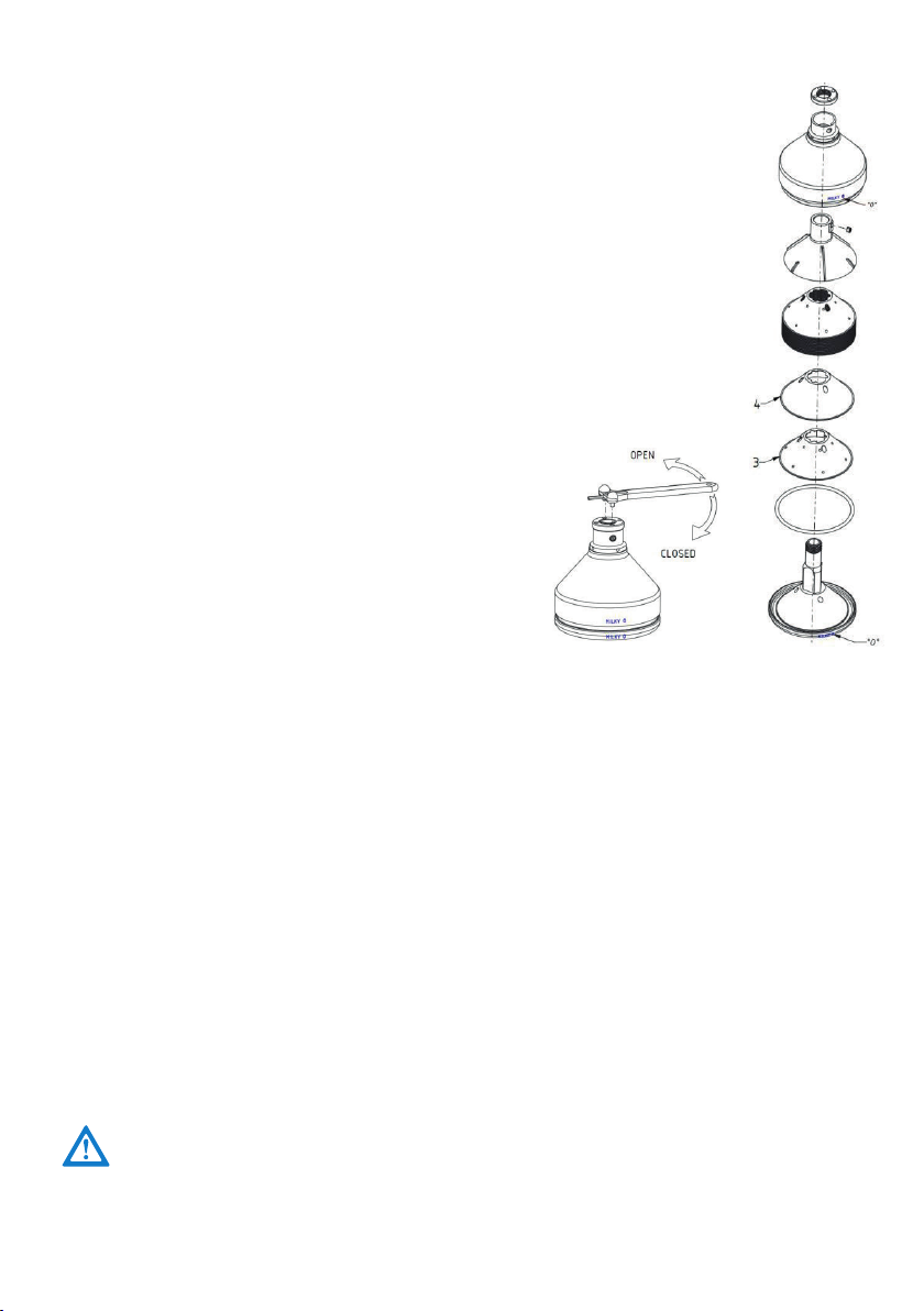
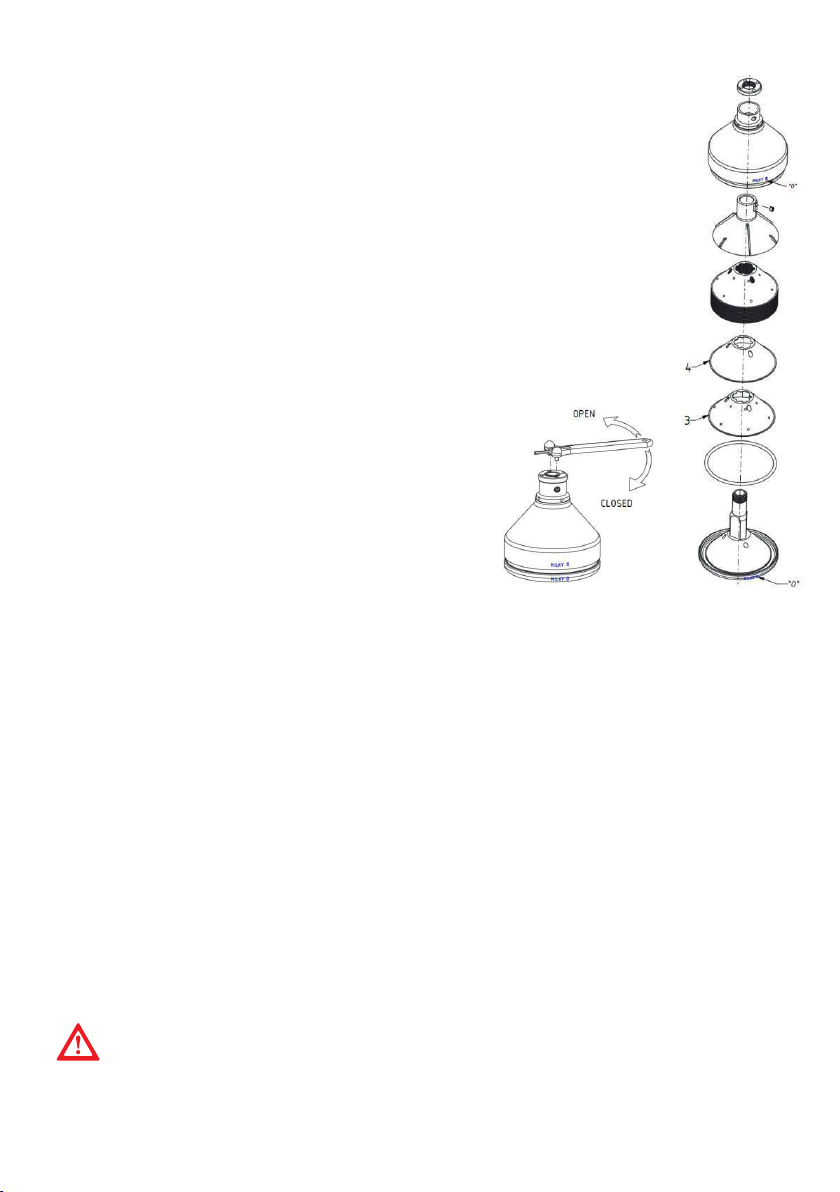
TOP BOWL ASSEMBLING PROCEDURES
1. Put the rubber washer into the notch of top bowl bottom part.
2. Place the metal discs in the top bowl. Take care with the placement of the
discs - device uses two different types of disks - plain and relief discs. First,
insert relief disc, then plain disc and repeat the procedure until all discs are
placed. Avoid any use of strength while placing the discs. With gently shaking
and turning of the top bowl bottom part all the discs will find their place very
easily.
3. Put plastic partition in the top bowl cover part.
4. Place the two parts (top and bottom part) of the top bowl together. Take
care that top bowl top part marked with ˝0˝ and top bowl bottom part ˝0˝
are in the same place and direction.
5. Screw the top bowl fixing nut with hand and fix it strongly with the fixing
key. The mark ˝0˝ must stay in the same direction.
The fixing nut must be strongly fixed, because it is
exposed to high forces.
3 Plain disc
4 Relief disc
17
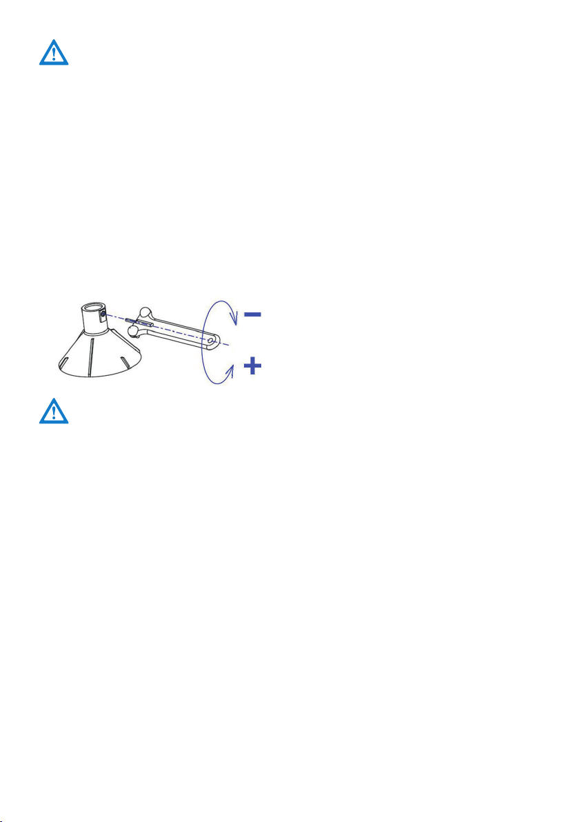
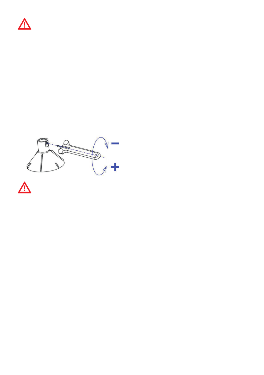
SKIMMING REGULATION
The cream separator is factory adjusted with around 10 % of cream from whole milk volume
at milk temperature 35 °C. It is possible to adjust this percentage due to different conditi-
ons like density or volume of cream. Adjust hexagonal adjusting cream screw by turning it
(placed in the plastic partition in top bowl upper part).
• For more density cream – less volume, turn it towards right (clockwise)
• For less density cream – higher volume, turn it towards left (counter clockwise). In most
cases it is enough to turn the adjusting screw for ¼ of the rotation.
Cream adjusting screw details and function
TAKE CARE, NOT TO FIX THE ADJUSTING CREAM SCREW TOO DEEP. THIS CAN
CAUSE HARM TO THE SCREW COIL. DON’T UNSCREW THE REGULATION SCREW
TOO MUCH. THIS CAN CAUSE PROBLEMS WITH DISASSEMBLING THE PLASTIC
PARTITION AND THE TOP BOWL UPPER PART.
PLEASE NOTE! After you have finished skimming, pour approximately 1/2 l of skim-
med milk back into milk container. This will clean the rest of cream in the top bowl.
After all procedures are finished, simply turn OFF the device and wait until motor
stops. Always check, whether the rubber washer is damaged or too much exten-
ded. In such cases please replace it with a new one.
- less cream volume and higher cream density
+ higher cream volume and less cream density
MAINTENANCE AND CLEANING
• All parts of the top bowl should be cleaned with hot water with some detergent.
• Rests of milk, cream or other impairs should be cleaned with soft duster or cleaning
brush. Especially take care to clean very precisely all the holes in top bowl upper part,
top bowl bottom part and in adjusting screw. For cleaning these parts, a cleaning brush
is strongly recommended! Other parts of the separator, which come in touch with milk,
should also be cleaned with hot water in which a detergent is added. Then rinse parts in
clean water.
• If milk or cream rests get dry, do not remove them with sharp objects or sharp duster. It
can easily happen, that the galvanic protection cover or plastic parts are damaged.
• Before cleaning cream separators housing, disconnect device from mains. Clean it first
with wet duster and then try it with dry duster. Take care, that water doesn’t come into
the device.
Ensure, that no water comes in contact with the motor and other electric parts.
The device is protected against direct water access, please take care and avoid, that
water comes into the device.
Before cleaning, always disconnect the Cream Separator from the mains supply.
18
IF IT IS NOT POSSIBLE TO MOUNT OFF THE TOP BOWL FROM THE MOTOR AFTER
SKIMMING, PLEASE SHAKE IT GENTLY.
PLEASE AVOID TO USE FORCE – IT CAN CAUSE HARM TO THE DEVICE AND MOST
OF THE PARTS.
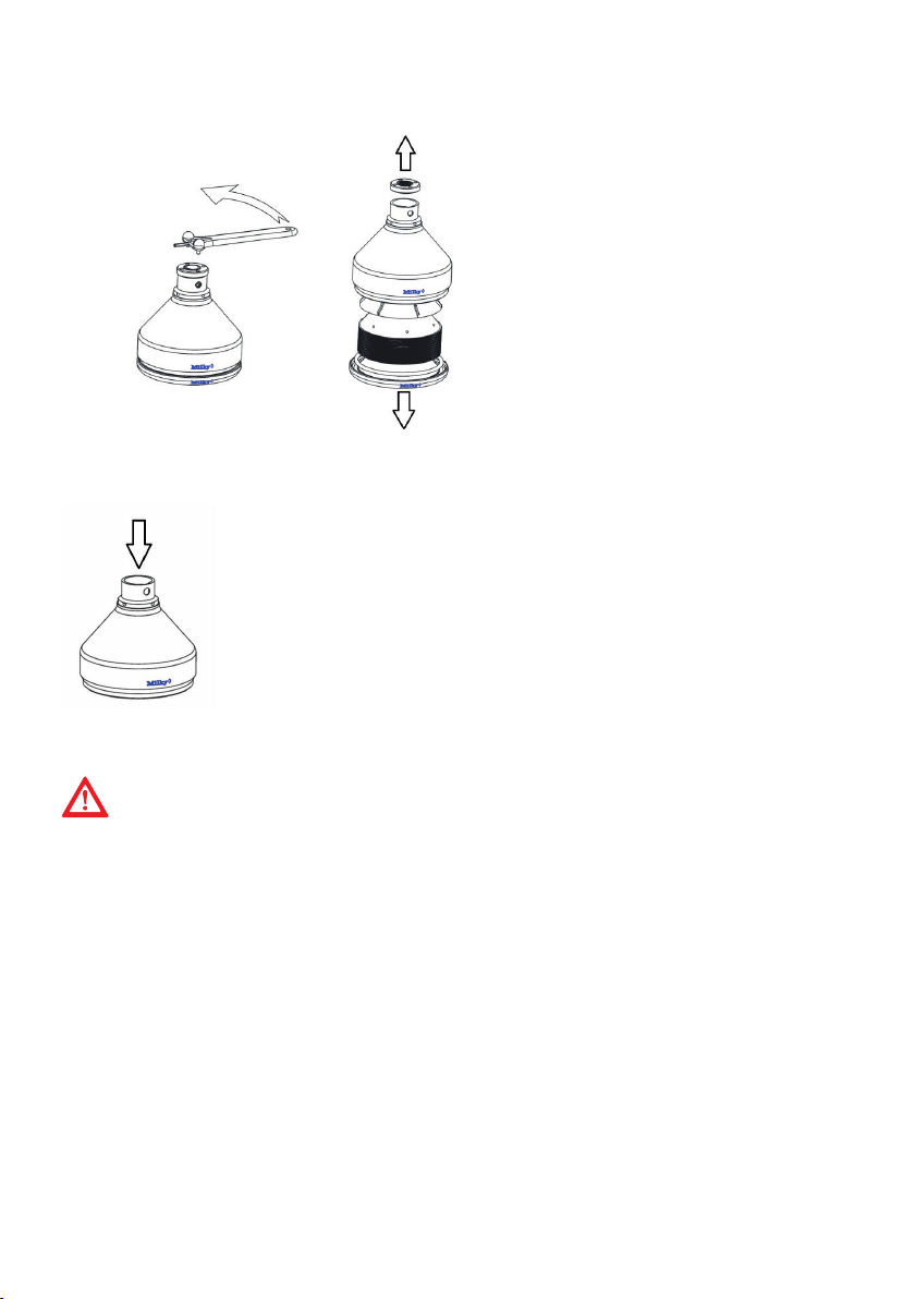
TOP BOWL CLEANING PROCEDURE
With the key, which is packed with the cream separator, unscrew the top bowl fixing nut
as it is shown on the picture below.
The easiest way to perform this procedure is:
1. Fix key into the holes, which are on the top bowl fixing nut.
2. Press the key down and turn it until the fixing nut is released. It is
now possible to unscrew the fixing nut by hand.
3. Dismount the top bowl cover with the help of the key and separate
all different pieces, which are found under the cover - plastic partition,
metal discs and rubber washer. Clean them with hot water. To achieve
better results, cleaning detergent can be added to the hot water.
4. Wash all the parts with hot water and dry them with dry and
soft duster.
5. Never wash the discs in the dishwasher!
19
PART LIST
Name Part. no.
1 Foot 3711019
2 Bottom cover 3171017
3 Motor 230 V 17595
3 Motor 115 V 17596
4 Mains switch 371151
6 Housing - blue 37005B
7 Mains cord assembly 230 V 26002
7 Mains cord assembly 115 V 26003
9 Bearing cover 3711013
10 Top bowl assembled 375021K
11 Milk outlet 3711037
12 Cream outlet 3711039
13 Container holder - blue 3711041
14 Floater plastic 3752045
15 Container 370000
17 Closing cork 3711061
DRAWING OF THE CREAM SEPARATOR
20
Teileliste der Trommel
Ersatzteil
Art. No.:
1.
Trommelunterteil
Trommeldeckel
Trommelmutter
SE 404930
2.
TRommelmutter
SE 403202
3
Trommelteller 1
SE 403203
4
Trommelteller 2
SE 403503
5
Schneideteller
SE 404203
6
Gummiring
SE 102679
PART LIST TOP BOWL
Name Part. no.
1 Rubber washer 3711033
2 Metal disc 3711025
3 Metal disc - middle 3711026
4 Plastic partition 3711029
5 Fixing key 3712069
6 Cream Screw 103444
This manual suits for next models
2
Table of contents
Languages:
Other Milky Farm Equipment manuals


Popular Farm Equipment manuals by other brands


Opico
Opico SWARD SLITTER Operation manual & safety instructions

TATU
TATU GAPCR-HD 8013 Operator's manual

Valtra
Valtra HiTech N Series Operator's manual

Raven
Raven RS1 Guidance and Steering Installation Manual

ChickenGuard
ChickenGuard B07G9MPCKT instructions

cormidi
cormidi 50 Series User manual and maintenance