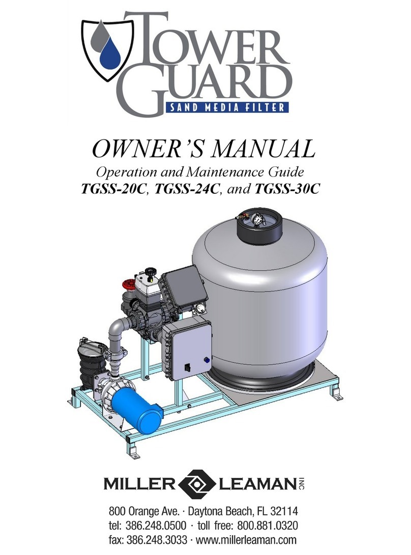
Miller-Leaman TOWER GUARD TGSS-20T User manual

OWNER’S MANUAL
Operation and Maintenance Guide
TGSS-20T, TGSS-24T, and TGSS-30T

2
First Edition
Copyright © 2017 by Miller-Leaman, Inc. - 800 Orange Avenue, Daytona Beach, FL 32114
Printed in the United States of America. All rights reserved. This manual or parts thereof may
not be reproduced in any form, mechanical, electronic, Internet, or in any form without the
written permission of Miller-Leaman, Inc.
Toll Free: 800 881-0320 • Phone: 386 248-0500 •Fax: 386 248-3033
Miller-Leaman, Inc.
•800 Orange Avenue • Daytona Beach, FL 32114 •
• Toll Free: 800 881-0320 • Phone: 386 248-0500 •Fax: 386 248-3033 •
• E-mail: [email protected]om • Web Site: www.millerleaman.com •

3
Introduction
Thank you for purchasing Miller-Leaman’s TowerGuard Filter System. With proper installation, operation, and maintenance,
the TowerGuard will provide trouble-free automatic filtration. This manual will provide the details required to understand the
function, design, operation, and maintenance of your filter. Please read this manual completely before installing and
operating the TowerGuard System. IT IS IMPORTANT THAT PERSONS WHO ARE TO OPERATE AND MAINTAIN THIS
SYSTEM FULLY UNDERSTAND THESE INSTRUCTIONS PRIOR TO OPERATION.
Please review the MAXIM Owner’s Manual section as well before operating the system. The MAXIM manual will explain the
system settings and how to adjust values such as the backflush frequency and duration.
Should there be any questions concerning the system, please contact our application specialists at 386-248-0500, or e-mail
us at sales@millerleaman.com.
The MAXIM Controller also contains a serial number to ID
the software and controller type.
This Serial Number is located on the left side of the con-
troller box.
MAXIM SERIAL NUMBER:
M4 - ___________
Each TowerGuard system is identified with a Serial Number
to ID the system’s components and records. The Serial
Number is located on the data plate label. This label is
typically placed on the MAXIM Controller cover plate outside
with a duplicate copy on the inside cover.
TOWERGUARD SERIAL NUMBER:
TG - ___________
TowerGuard Sand Filter
Tower Water Backflush Model
TGSS-20T 1P - 20” TowerGuard
with 1-Phase Pump
TGSS-20T 3P - 20” TowerGuard
with 3-Phase Pump
TGSS-24T 1P - 24” TowerGuard
with 1-Phase Pump
TGSS-24T 3P - 24” TowerGuard
with 3-Phase Pump
TGSS-30T 1P - 30” TowerGuard
with 1-Phase Pump
TGSS-30T 3P - 30” TowerGuard
with 3-Phase Pump

4
1) Introduction........................................................................................................................ 3
2) Safety ................................................................................................................................ 4
3) Introduction to TowerGuard Automatic Filtration ................................................................ 5
4) TowerGuard - Tower Water Backflush Model - Description................................................ 6
5) TowerGuard Installation Guidelines and Procedures ......................................................... 7
6) System Startup and Shutdown........................................................................................... 9
7) Filter Maintenance ......................................................................................................... ..11
8) TowerGuard - Tower Model Spare Parts List .................................................................. 11
9) TowerGuard Side Mount Sand Filter Parts List ................................................................ 12
10) MAXIM Backflush Controller Introduction & Installation ................................................... 13
11) Differential Pressure Gauge Connections and Set Point ................................................. 13
12) Electrical Detail (Power, Outputs, & Inputs)...................................................................... 14
13) Viewing the Menu Screens & Adjusting Values................................................................ 15
14) Initial Power Up Screen Sequence................................................................................... 15
15) Monitoring the System Status Screens ............................................................................ 18
16) Warranty .......................................................................................................................... 20
Table of Contents
Safety
Safety Considerations
Safety precautions are essential when any filtration equipment is involved. These precautions are necessary
when using, storing, and servicing your filter. If safety precautions are overlooked or ignored, personal injury or
product damage may occur. Your filter was designed for specific applications. It should not be modified and/or
used for any application other than originally specified. If there are any questions regarding its application or
installation, contact Miller-Leaman, Inc.
ALWAYS OBSERVE THE FOLLOWING PRECAUTIONS:
1) Read this manual carefully.Consider the applications, limitations, and the potential hazards specific to your
filter.
2) Absolutely, under no conditions, should the filter vessel cover, pressure gauges, or valves be
removed while the filter is pressurized.
3) Units with damaged or missing parts should never be operated. Contact our customer service
representatives for replacement parts.
4) This filter system is not freeze protected. If the liquid filled components freeze, system damage may occur.
If there is a risk of freezing, install the system indoors or freeze protect its components with heater tape and
insulation.
5) Do not connect the pump inlet to a pressurized line as these systems are designed for side-stream
applications only.
NOTE - At no time should the internal vessel pressure exceed the maximum
rated pressure of 50 PSI.

5
Sand Media Filtration —The Miller Leaman TowerGuard Filter series utilizes sand media as a means to filter cooling
tower water. The TowerGuard will remove suspended solids as low as 10 microns with standard sand media. The
system is designed for side-stream applications only.
TowerGuard Design - The design of the TowerGuard allows for simple automatic water filtration. The TowerGuard
starts with a durable welded stainless steel frame to support its components. A fiberglass reinforced vessel is con-
nected to a TEFC pump via Schedule 80 PVC. The MAXIM Controller switches two electrically actuated 3-way valves
in order to divert flow for the backflush cycle.
The major system components are identified and described in the table below. Please reference the Product Specifi-
cation for your system’s specific component identification, as the TowerGuard systems come in multiple sizes depend-
ing upon the desired flow rate.
Introduction to TowerGuard Automatic Filtration
System Components
Frame / Skid
The T304 stainless steel welded frame supports the system components while providing high durability and
strength.
Filter Housing
The fiberglass reinforced polyester filter housing which contains the sand media bed. This housing is sized
for the system’s flow rate.
Pump
The TEFC pump is matched to the flow rate of the filter and provides the necessary flow of water through the
sand media filter.
MAXIM Backflush Controller
The MAXIM backflush controller monitors the system’s pressure differential and controls the backflush cycle.
It can actuate a backflush cycle by pressure differential (PD), elapsed time, or manually by a user selection.
All of the backflush parameters are user adjustable via the MAXIM’s user-friendly menus.
System Piping
The inlet and outlet manifolds direct the flow of water to and from the filter housing. The piping is constructed
of Schedule 80 PVC.

6
Figure 1. TowerGuard System Layout using the Tower Water backflush hookup.
Modes of Operation
Filtration:
During normal filtration, water is pumped to the filter via the internal riser pipe assembly and evenly
distributed over the media. As the water travels down through the media bed into the under-drain,
suspended particles are trapped. When the filter media requires cleaning, Miller-Leaman’s MAXIM
Controller will trigger a backflush cycle and automatically clean the filter. This may be triggered by
the differential pressure sensor, the backflush timer, or manually by the user.
Backflush:
Once a backflush is initiated, the pump will turn off while the valves rotate to the backflush position.
When the valves are in the backflush position the pump is turned on. The reverse water flow lifts
and churns the media bed creating a scouring action to release the captured debris. This debris is
then flushed out of the backflush manifold. The filter is configured to be backflushed with source
water from a Tower Water Supply. After the backflush cycle is completed, the pump turns off while
the valves rotate back to the filtration position. When the valves are in the filtration position the
pump turns back on and normal filtration resumes.
TowerGuard - Tower Water Backflush Model
Figure 2.
Figure 3.

7
Installation Guidelines and Procedures
Please carefully read the following procedures and guidelines for your system. Implementing these procedures and
guidelines will prepare your TowerGuard Filter System for operation.
Installation and Anchoring
1. The TowerGuard Series filter system has been designed to be easily lifted from under the frame. If lifting straps
are used, place them underneath the frame, positioned so they do not come in contact with any of the filter
components. NEVER lift the system via any of the filter components.
2. The TowerGuard Series filter is designed for side-stream use only. The inlet to the system should draw from a
non-pressurized location, such as a cooling tower sump. This system should NEVER be installed in a
pressurized and/or full-flow application.
3. Each TowerGuard contains four anchor points. The system should be placed on a firm, supporting level surface
and securely anchored. Miller-Leaman recommends that a concrete pad be poured for the filter frame to rest on.
Piping and Connections
1. The TGSS-20T and TGSS-24T inch TowerGuards should be plumbed with 2” piping, and the TGSS-30T inch
with 2-1/2 inch piping. Reducing the piping size may result in loss of flow. Make sure to support all piping to
and from the filter to eliminate stress on the filter components.
2. Manual valves should be installed in each line to allow the system to be isolated for maintenance. However, the
user must make sure that all valves are open prior to running the system. It is also recommended that unions be
installed on each connection to allow for easier maintenance should the system ever have to be disconnected
completely.
3. Connect the influent line from the sump to the pump. If the water level is below the pump inlet, a check valve or
foot valve should be installed. The water inlet line should NOT exceed 10 PSI.
4. Connect the effluent line from the system outlet back to the cooling tower sump (or to sweeper piping).
This line should not connect into a pressurized line.
5. Connect the backflush line from the port labeled “Backflush” to a drain. Do not place any valve or restriction in
this line and make sure this line drains to a non-pressurized location. Be sure the drain is capable of handling
the backflush flow rate. If not, a reservoir tank may be installed to collect the backflush water and allow it to
slowly drain out.
Insure the backflush water is properly disposed and meets all local code requirements.

8
Electrical Connections / Controls
1. Each TowerGuard requires a single point electrical connection to the pump motor starter box. See the Electrical
Schematics in the Engineering Drawings section. See the system product specification or system identification
label for the electrical requirements.
2. Insure the correct voltage and amperage is supplied to your system. Customer Power Supply should include a
local disconnect that is fused or uses a circuit breaker sized to provide appropriate protection to the TowerGuard
Filter System. Follow all local code requirements and NEC standards when installing field wiring. A Phase Se-
quence Indicator and Motor Rotation Tester should be used to determine the correct wiring for pump rotation.
Also, see Initial Start Up Procedure, steps #9 & #10, on page 9.
3. The TowerGuard backflush is monitored and actuated by a MAXIM Controller. See the section on the MAXIM
operation for a complete explanation of the controller functions and connections.
Loading Sand Media
The recommended sand is .45 to .55mm and meets the AWWA B100 requirement.
1. Before filling the vessel with sand media, do a visual check of the laterals. Look for broken or loose laterals.
Replace if necessary.
2. To eliminate stress on the laterals, fill the filter vessel with enough water (Approx.1/3) to provide a cushioning
effect when the sand media is poured in.
3. The filter will require a sand media bed depth, which shall extend to an approximate level below the top of the
hydraulic distribution lenses. See Figure 1
4. For TGSS-20T and TGSS-24T inch Sand Filter models, Remove the top diffuser from the internal diffuser pipe
and place the flexible air relief tube to the side and out of the way, inside the filter vessel. Cap the internal dif-
fuser pipe with the sand shield that is provided to prevent sand from entering the pipe. DO NOT MOVE THE
DIFFUSER PIPE, as this can affect the integrity of the bulkhead seal.
NOTE - The above instruction does not apply to the TGSS-30T inch Sand Filter models. Any sand
media entering the diffusers will be removed during normal filter operation.
5. Wash all of the sand media and debris away from the threads of the filter vessel top cap area.
6. Lubricate the O-ring or gasket (bolt down type) MPV and thread into the filter. The lubricant should be silicone
based and NOT petrochemical / oil based lubes
7. Thread the Top Cap onto the filter tank. Hand tighten only - do NOT use excessive force.
Changing Sand Media
1. Ensure that the Controller, pump, or water supply is turned off and all valves are in the off position.
2. Removal of the sand media can be done with the use of a slurry pump which will suck out the fluidized me-
dia.
3. Remove the top manhole cover and ensure that there is sufficient water to fluidize the sand media so the slurry
pump can be used taking care not to break the lateral while the last portion of sand media is being removed.
Approximate.
Fill Level
Sand Media
TGSS-20T - 200 lbs.
TGSS-24T - 310 lbs.
TGSS-30T - 460 lbs.
Figure 4.

9
Startup and Shutdown
Prior to start-up, read and fully understand the MAXIM Owner’s Manual section.
Initial Start-up / Seasonal Re-start
Always inspect the filter system prior to start-up or after an extended shutdown period.
1. Before pressurizing the system, check that all clamps, bolts, lids, and system accessories are properly fastened.
2. Load the sand media - see procedure on page 8. (Disregard for seasonal re-start)
3. MAXIM Controller Settings: With the pump starter HOA switch in the “OFF” position, turn the MAXIM controller
switch to the ON position. Check the controller’s settings by scrolling through the menu screens. See the
controller recommendations in the Adjustable Values section. After verifying settings, scroll thru the menu to the
Status screen. When the controller is powered ON, the valves are allowed to rotate to the Filtration position. After
60 seconds, the Status will be AUTO.
4. Open all isolation valves and allow the system to fill with water. Make sure the backflush drain is not restricted.
5. Open the air vent located on top of the sand filter housing.
6. Prime the pump by filling the suction line and pump volute with water. If the main pump does not have a flooded
suction, then a foot or check valve is required to maintain a prime after shutoff. For a flooded suction, prime the
pump if needed.
7. Close the Outlet Throttle Valve by turning the handle fully clockwise, then open the valve 2 turns.
8. Refer to the System Labels on the Maxim Controller box. There is a duplicate label on the inside cover.
Maximum operating pressure (50 PSI) and Maximum flow are listed on this label. These must be adhered to
during start up.
9. Using the pump starter HOA switch, momentarily bump start the motor by switching to “HAND” position, only
long enough to verify that the motor is wired to rotate in the direction shown by the arrow.
10. After confirming that the motor is rotating in the right direction.
11. Turn on the system by switching the pump starter HOA switch to “AUTO” mode. AUTO mode will allow the
controller to turn the pump ON/OFF as required. Note that the controller power switch must be ON in order for
the pump to start.
12. While observing the pressure gauge on the top of the filter, rotate the Outlet Throttle Valve until the gauge is
reading approximately 25 PSI.
13. Due to variances at site locations such as installation pipe sizes, pipe lengths, elevation, etc., the Outlet Throttle
Valve may require further adjustment to optimize the desired flow. Never exceed the specified maximum pres-
sure or specified maximum flow.
14. Check the setting of the Pressure Differential Gauge. Factory and initial setting should be 12 PSID. See the
Differential Pressure Gauge information in the Maxim Owner’s Manual section.
15. Close the air vent once there is a steady stream of water.
16. Check all system components to ensure there are no leaks.
17. If the system has new sand media installed, run a complete backwash cycle. This will purge any excess fine
particles from the system. To start a cycle, press OK on the controller’s Status Screen. See the “Monitoring the
System Status and Initiating a Backflush” section in the Maxim Owner’s Manual section of this manual for
information on normal Backflush sequence.
18. Once the backflush is complete, the system will automatically resume normal filtration.

10
Cold Weather Operation
The TowerGuard Series filter does not come freeze protected. It is preferable to install the system in a heated room
to prevent freezing. If this is not possible, the system should be properly protected with heat tape and insulation
around all of the liquid filled components. The filter should be completely drained when not in use to prevent
potential freeze damage.
Shutdown - For an extended length of time
Follow the procedure below when the system will be shut down for a prolonged time period.
1. Run the filter through a complete backflush cycle to clean the sand media.
2. Turn off the pump and the controller, making sure the system is in normal filtration mode when turned off. Shut
off and lock out all electrical power to the system.
3. Isolate the system by shutting off all valves that may allow water into the system. Open the air relief valve on top
of the filter housing. Drain the system allowing all water to drain by removing the drain plug on the bottom of the
filter. Replace the plug once the system is completely drained.
4. Remove the filter lid and inspect the over drain assembly. Remove any foreign material from the media.
Replace the media if necessary. Clean and lubricate the O-ring if necessary and reinstall the lid.
5. Close the air relief valve.
Recommended MAXIM Controller Settings
MAXIM Controller - The controller should be monitored on a regular basis to make sure the system is operating
normally. See the MAXIM Controller Owner’s Manual in the following section for operating instructions. The
controllers initial settings are factory preset at average values and do not necessarily reflect the individual needs for
your system. Below are recommendations on how to adjust the controller to fit your system’s needs.
1) The Pressure Differential (PD) gauge setting should be properly set once there is water flow in normal filtration
mode. The recommended PD set point is 7.2 PSID above the “clean” gauge reading at the system’s MAXIMUM
flow rate. Typical PD gauge set points are between 12-15 PSID, depending on flow rate and filter size. Setting the
PD gauge too low will cause the system to backflush too often, resulting in significant water loss to drain. The
initial factory setting of the PD Gauge is 12PSID. See additional PD Gauge info on page 14.
2) The backflush frequency setting should be adjusted so the system backflushes by elapsed time just before the
system reaches it’s pressure differential set-point. If the system is installed on an older tower, you may find the
system backflushes frequently until the tower water has “cleaned up”. We recommend the user begin with a 24
hour backflush frequency setting. This can be adjusted depending upon how often the pressure differential
set-point is reached.
3) The backflush duration recommended initial setting is 180 seconds. This may be increased or decreased de-
pending upon whether or not the backflush water is becoming clean by the end of the cycle. We do not however,
recommend ever adjusting this value below 90 seconds. Take note of the original “clean filter pressure differen-
tial”. When a backflush is complete, the Pressure Differential (PD) gauge reading should fall back to this level. If
it is not returning to this level, you may want to increase the backflush time. If the problem continues, inspect the
sand media and consider replacing it.

11
Maintenance
A regular scheduled system maintenance program is important in keeping your system at it’s best performance. Always fol-
low start-up procedures after the system has been shut down for maintenance.
Routine Inspection
Visually inspect this system, looking for any leaks or unusual noises.
Verify the pump is operating and that the pump inlet connection is secure. Also verify that the supply line is not
blocked by debris or restricted in any way.
Ensure that the controller is properly working, and that all backflush settings are properly adjusted. Check that the
system is not backflushing too often by Pressure Differential (PD gauge).
Check the system pressures. Make sure the Pressure Differential (PD) gauge is set at the correct PD setting and that it
properly initiates a backflush. Be sure the system pressure never exceeds 50 PSI, vessel pressure rating.
Manually start a backflush to make sure both valves are actuating and the filter is backflushing properly.
Seasonal Maintenance
Remove the filter vessel cover. Check the sand media condition and replace if necessary. If the sand media is
removed, inspect the internal piping assemblies. Clean and lubricate the O-ring before reattaching the cover.
Inspect the system for any leaks. This should include all of the union couplings. The O-rings should be lubricated
with silicon gasket grease to prevent them from drying and cracking.
Check all of the 3-way valves to make sure they are operating properly. If the valves are not rotating correctly, remove
the tops and inspect the motor / gears. Contact Miller-Leaman customer service if this condition exists.
Tow erGuard - Tow e r Model Spare Parts List
TGSS Part Number Part Description Qty per Filter
PS01328 20 inch Sand Filter Vessel - Complete Assembly 1
PS01329 24 inch Sand Filter Vessel - Complete Assembly 1
PS01330 30 inch Sand Filter Vessel - Complete Assembly 1
ML21334 Outlet Gate Valve Assembly 1
PS00034 Pressure Gauge 0-150 PSI range, Dry 1
ML21354-01 Differential Pressure Gauge 15 PSID range 1
PS00411-1HP-1P 1.0 HP - 44GPM 1 Phase Pump Motor 1*
PS00411-1HP 1.0 HP - 44GPM 3 Phase Pump Motor 1*
PS00295-1.5D1P 1.5 HP - 62GPM 1 Phase Pump Motor 1*
PS00295-1.5D 1.5 HP - 62GPM 3 Phase Pump Motor 1*
PS00295-2C1P 2 - HP - 98GPM 1 Phase Pump Motor 1*
PS00295-2C 2 - HP - 98GPM 3 Phase Pump Motor 1*
PS00373 Mechanical Seal for NPE Series Pumps 1
PS01827 Trap Assembly, Pump Pre Filter 1
ML20270 -01 Actuator Flow Valve #1 Upper - Tower model 1
ML20270 -02 Actuator Flow Valve #2 Lower - Tower model 1
ML20995-20 Motor Starter Box - Complete Assembly 1
ML20639 -04L
MAXIM-4 Controller box - Tower model 1
Figure 3 - TowerGuard - Tower Backflush Model Spare Parts List
* Note - Selection is System dependent.
TowerGuard - Tower Backflush Model
Spare Parts List

12
Figure 5 - TowerGuard Sand Filter Vessel Parts List
TowerGuard
Side Mount Sand Filter

13
MAXIM - State-of-the-art Filter Backflush Controller
The TowerGuard Filter System is controlled by the MAXIM, a state-of-the-art
backflush controller designed for automatic filtration systems. The heart of the
MAXIM is a programmable micro PLC, custom designed to maximize the per-
formance of your filtration system. These components are protected by a robust,
corrosion-proof watertight enclosure.
The MAXIM is operated and adjusted through the user-friendly menu screens
that give the user control of all critical automatic filter functions. The backlit
LCD display provides real-time system status. The controller includes a mem-
ory module (EEPROM) port that allows for installation of system upgrades and
provides the ability to download custom, application specific programs without
the need for a computer.
Introduction
Installation
The MAXIM controller is pre-installed as a component of the complete TowerGuard filtration system. Follow
the directions below only if it is necessary to connect electrical or gauge connections.
Electrical Connections:
The Maxim controller is pre-wired as part of the Automatic TowerGuard Filter System.
Note: When using an external power source, the input power to the PC Board must be the same as indicated on
the upper left side of the Maxim Controller. Typically, the controller is either 24 volts AC, or 24 volts DC,
however some controllers use 120 volts AC or 12 volts DC.
Additional connections to the Outputs should be made to the corresponding Output (+) and a Common (-) ter-
minal on the circuit board. The Pressure Differential Gauge and Timer ON Enable inputs are connected to a
corresponding Input and Auxiliary Power Out (+) terminal on the Maxim circuit board.
Review the Electrical Detail section prior to making any connections to the controller. If requested custom
input/output capabilities are not described in this manual, please refer to an attached addendum.
Differential Pressure Gauge Connections:
Connect the pressure differential (PD) gauge to the system’s inlet (high/BLK) and outlet (low/BLU) pressure
ports.
WARNING: Failure to use a second wrench on the low pressure
port when tightening fittings may result in damage to the internal
pressure tubing.
Be sure all connection tubing is clean prior to installation on the
gauge. The gauge contains orifices that may become clogged by
larger particles.
CAUTION: Make sure not to foul the pressure orifices with pipe
dope or dirt, as the gauge will not operate.
Differential Pressure Gauge Set-point:
Adjust the front face needle contact to the desired PD set-point that will trigger a backflush cycle. The recom-
mended PD set point is 7.2 PSID above the “clean” gauge reading at the systems MAXIMUM flow rate. Set-
ting this gauge at low flow may result in continuous backflushing at higher flow rates, since the Pressure Dif-
ferential increases with flow rate. Typical PD gauge set points are between 12-15 PSID, depending on the flow
rate. Initial factory PD Gauge setting is 12 PSID.

14
The circuit board layout shown applies to the M4 controllers. The M# in the serial number on the left side of the
enclosure designates the controller’s total number of outputs. For example, a MLI-M4-xxxxx has 4 available out-
puts (uses board outputs 1-4 only, leaving outputs 5 through 10 unused). Review the connection details below be-
fore wiring to the controller.
CAUTION: Unplug controller from power source before removing cover!
A. Power supply connections:
115VAC Power In - used only on previous versions. The Transformer is now located in the Starter Box.
12VDC/24VDC/24VAC Power In provides power to the controller and circuit board connections. This
power is typically provided from the power supply / transformer.
Note: The standard Power Supply provides a maximum total power output as listed below. Exceeding the
maximum available power may trip the fuse repeatedly or overload the power supply / transformer. The fuse
is an automatic resetting type and will reset itself within a few seconds of being tripped.
Maximum power available: 12VDC or 24VDC - 24 Watts; 24VAC - 48 Watts
B. Outputs:
The outputs provide a voltage output (same as controller’s voltage) to control the backflush valves, pump
starter, etc.
Note: Any Common (-) connection may be used for the common/negative terminals of the solenoids/valves.
Output 1: Spare
Output 2: Backflush valves actuate for backflush flow. This output is activated at the beginning of a back-
flush cycle to reverse water flow through the filter. The output energizes a relay, Item D, to select the
“Open to Backflush” position of the valves. When the output is turned off, the relay is de-energized to se-
lect the “Close to Filtration” position of the valves.
Output 3: Backflush Master - used to signal a backflush cycle is in progress.
Output 4: Pump Starter. This turns the pump off while the valves are changing positions during a backflush
cycle. The pump must be operated in “Auto” mode for this to occur.
C. Inputs:
The inputs provide signals into the controller.
Digital (on/off) inputs require a voltage input that
matches the controller’s operating voltage. The
controller inputs are listed below.
Standard Inputs:
Input 1 - PD Gauge - I1 and Auxiliary Power
Out (+) are connected to Normally Open con-
tacts on the PD gauge. Once the PD set-point is
reached, the contacts will close and signal the
controller to start a backflush cycle.
Input 2 - Timer ON Enable - an AUX contact on
the Pump Starter is wired though to this input.
When the pump is running, Hand or Auto,
this input will be on and allow for a timed
Backflush to occur.
Electrical Detail
B C
A
D

15
Scrolling through Menu Screens
The MAXIM controller allows the operator to scroll through a selection of menu screens by pressing the
Aor Bbuttons. Press Ato scroll backward to the previous menu or press Bto scroll forward to the next
menu. The LCD backlight will automatically turn on for 5 minutes when a button is pressed, thus al-
lowing the operator to easily view the menus in low light situations.
Initial Power Up Screen Sequence - after first turning on the Maxim Controller, or after a restart
caused by a loss of power, this will be the screen sequence that is displayed.
Initial Power Up Screen - the company contact information,
or Screen 08, is displayed for the first 5 seconds. This allows
time for controller initialization while the pump is turned off
for the valves to be turned back to the filtration position.
Status: ON Valves to Filtration Screen - after the pump has
been turned off the valves will be turned back to the filtration
position, or closed. This will take approximately 60 seconds.
During this time the display will be changed to the Status
Screen, or Screen 01, which will indicate that the Valve are be-
ing moved to the Filtration position.
Company Contact Information Screen - after 60 seconds,
the Valves will be closed, or in the Filtration position. The Dis-
play is changed back to the company contact information, or
Screen 08. The pump will be turned on and normal filtration
will resume. Press the B button to scroll forward to the Status
screen.
Viewing the Menu Screens & Adjusting Values
Miller-Leaman Inc
800-881-0320
millerleaman.com
12/07/11 12:09__
.
Status: ON
Valves to
Filtration
Press ESC to Stop_
.
Miller-Leaman Inc
800-881-0320
millerleaman.com
12/07/11 12:09__
.

16
This next section describes the menus in the order they are seen by scrolling with the B button from
the Company Contact Information Screen at the completion of the Initial Power Up Sequence.
Screen 1 - Status Screen 2 - Tower Water Screen 3 - BF Interval
Note - pressing the B button to scroll forward from screen 8 - Company Contact Information screen,
causes the display to cycle back around to the beginning and display the Screen 1 - Status Screen.
Also pressing the A button to scroll backwards from Screen 1 - Status screen, causes the display to
cycle back around to the end and display the Screen 8 - Company Contact Information screen.
Screen 4 - BF Duration Screen 5 - Time Since Last Screen 6 - BF Counters
BF & Triggered By Trip & Life
Screen 7 - Machine & Screen 8 - Company
Controller ID Contact Information

17
Changing Values
To change an adjustable value, first scroll to the appropriate menu screen using the Aor Bbutton.
Follow the directions below to modify the value.
1. The current selected value will show flashing blocks. Use the + or - keys to select another value if desired.
2. Press OK on the selected value. The value will change from flashing blocks to flashing numbers.
(Flashing blocks indicate the value is locked into memory. Flashing numbers indicates the value is unlocked
and can be changed.)
3. Press the + or - buttons to change the value.
(Holding the + or - button will allow the value to increase at a faster rate after the first 10 increments have
passed.)
4. When finished, press OK to save the change to memory. The value will return to flashing blocks.
5. Press the OK button a second time to save the value.
The following screens contain values that are operator adjustable. The controller’s factory preset values may not
be the final operating values. These values should be adjusted to meet the filters backflush requirements. Refer-
ence the filter manufacturer’s owners manual for additional information.
Backflush Interval: The user-defined interval at which the system will
initiate an automatic backflush cycle. The backflush Interval timer
resets after any backflush cycle occurs (by timer, PD gauge, or opera-
tor). This value is adjustable from 1 minute to 1000 hrs. Setting both
values to zero will turn off the backflush timer. It is recommended that
the operator adjust the backflush interval timer so that the system back-
flushes by the time before the pressure differential is reached. Factory
Preset value is 24 hours.
Backflush Duration: The time allotted for the actual backflushing of
the filter once the valves have been opened to the backflush position.
This time is set according to the type of filter and the nature of the
material being filtered. This value is adjustable from 1.0 to 600.0 sec-
onds. Factory Preset value is 180.0 seconds.
Backflush Duration
Seconds: 0180.0
__________________
.
Backflush Interval
HOURS:MM 00024:00
__________________
.
Adjustable Values

18
Monitoring the System Status & Initiating a Backflush
The Status Screen displays the current mode of the controller. It also al-
lows the operator to manually start or stop a backflush cycle. There are
three ways that a backflush cycle can be initiated:
1. Manually, following the instructions below.
2. Automatically, by elapsed time (per the backflush frequency setting).
3. Automatically, by pressure differential (as set by the PD switch-gauge).
To initiate a manual backflush, press the OK button while on the status
screen. At any time during the backflush cycle, press the ESC button to
stop the cycle.
The controller will automatically display the status screen if a backflush
cycle is initiated or if the pressure differential set-point is reached.
The current Status of the controller is displayed as follows:
1. AUTO - Indicates that the controller is waiting for a backflush cycle to
begin. The system is in normal filtration mode and flowing water. The
backflush frequency timer is running.
2. AUTO - High PSID - Indicates that a high pressure differential from
the PD Gauge has been sensed and that the controller is about to start a
backflush cycle.
3. ON - Indicates that the system is in backflush mode.
Valves to Backflush is displayed at the beginning of a backflush cycle
as the valves are redirecting water from normal flow to backflush flow.
The controller will automatically turn the pump off while it is changing
the valve positions.
Backflushing System is displayed when the pump is cycling water
through the system in backflush mode.
Valves to Filtration is displayed at the end of a backflush cycle as the
valves are returning to normal flow positions. The controller will auto-
matically turn the pump off while it is changing the valve positions.
Note - The Status: ON Valves to Filtration screen is also displayed in
the Initial Power Up Sequence. To insure proper filtration in the event
of a power failure, the valves are assumed to be in a non filtration posi-
tion, the pump is turned off, and the valves moved to the filtration posi-
tion. Then the pump is turned on and normal filtration is resumed.
4. ON - System Alarm - On any of the Status screens a System Alarm
screen can be activated. The second line down will alternately flash
>> System Alarm << and whatever was on line 2 before the alarm oc-
curred. The standard system alarm is the Consecutive Backflush Alarm.
This alarm occurs when the backflush cycle has been initiated three
times in a row by the Pressure Differential Switch (PSID). The Opera-
tor should verify proper operation of the PSID. The System Alarm can
be reset by pushing the red ESC button while a status screen is dis-
played.

19
The following screens provide system feedback. This allows the operator to monitor when and how the backflush cycle
is occurring. It is recommended that the operator adjust the backflush interval timer so that the system backflushes by
time before the pressure differential set-point is reached.
Controller Feedback
Backflush Counter:
The number of backflush cycles that have occurred since the counter
was last reset. This includes cycles initiated both manually and auto-
matically. This counter can be reset by pressing the ESC button from
the Backflush Counter screen.
Backflush Counters
Trip: 000012
Life: 000000097
Press ESC to Reset
.
Time Since Last Backflush: The amount of time that has elapsed since
the system last backflushed. The time displayed is in hours and min-
utes. This value does not include the elapsed time when the backflush
frequency timer is off (either when the Status Screen reads “Status:
Off” or when the controller is physically switched off).
This screen also displays how the last backflush was triggered. There
are three possibilities:
1) Operator - the backflush was manually triggered by an operator via
the status screen.
2) Timer - the backflush was triggered by time as set on the backflush
frequency screen.
3) PD gauge - the backflush was triggered by a high pressure differ-
ential, as set on the PD gauge mounted below the controller enclo-
sure.
Time Since Last
Backflush 0000:22
Triggered by:
Operator__________
.
Tower Water Backflush: The type of water used for backflushing the
system.
Note: The controller’s internal settings are set for Tower Water Back-
flush only. This setting is Read only, and has no user adjustment.
Tower Water
Backflush
__________________
.

20
Limited Warranty
800 Orange Avenue, Daytona Beach, FL 32114
Phone: (386) 248-0500 / Fax: (386) 248-3033
www.millerleaman.com
Hours: M-F 8:00 AM - 5:00 PM Eastern USA
Miller-Leaman warrants its products against defects in material and workmanship under normal use and service for which such products were
designed for twelve (12) months from factory ship date. Our sole obligation under this warranty is to repair or replace, at our option, any
product or any part or parts thereof we find to be defective.
MILLER-LEAMAN MAKES NO OTHER REPRESENTATIONS OR WARRANTIES, EXPRESS OR IMPLIED, INCLUDING,
BUT NOT LIMITED TO, ANY IMPLIED WARRANTY OF MERCHANTABILITY OR FITNESS FOR A PARTICULAR PUR-
POSE.
The warranty set forth above is the only warranty applicable to Miller-Leaman products. Our maximum liability shall not in any event exceed
the contract price for the product.
IN NO EVENT SHALL MILLER-LEAMAN BE LIABLE FOR ANY DELAY, WORK STOPPAGE, CARTAGE, SHIPPING, LOSS
OF USE OF EQUIPMENT, LOSS OF TIME, INCONVENIENCE, LOSS OF PROFITS OF ANY DIRECT OR INDIRECT INCI-
DENTAL OR CONSEQUENTIAL LOSS OR DAMAGES RESULTING FROM OR ATTRIBUTABLE TO THE USE OF THE
PRODUCT.
This warranty is governed by the Laws of the State of Florida. Venue and jurisdiction of any case or controversy related to the use of the prod-
uct or this warranty shall lie exclusively in the State Courts of Volusia County, Florida.
ML40015.pub (Revision 2-28-2017)
This manual suits for next models
2
Table of contents
Other Miller-Leaman Water Filtration System manuals
Popular Water Filtration System manuals by other brands

Aquamira
Aquamira CHEMICAL IV Series user manual
UV Dynamics
UV Dynamics UVD400E Installation and maintenance manual
NU Aqua
NU Aqua KF-600GPD-2FTL installation manual
STA-RITE
STA-RITE S7MD60 owner's manual
Pura
Pura UVB1 Installation manual & owner's guide
Oase
Oase BioTec ScreenMatic2 operating instructions

BWT
BWT Bewades 70W70/08 HI Installation and operating manual
Hayward
Hayward AquaRite + owner's manual
Barnstead|Thermolyne
Barnstead|Thermolyne NANOpure II owner's manual

Teesa
Teesa TSA0103 owner's manual
Pentair
Pentair EVERPURE BWS350 installation guide
Watts
Watts WQT4RO11-50 Installation, operation & maintenance manual
