Pura UVB1 User manual

INSTALLATION MANUAL & OWNER’S GUIDE
UVB SERIES UV20 SERIES
UVBB SERIES RACK SYSTEM
UV1 SERIES ADDON SERIES
Revision #: 1
Date: July 2015
36103017
ULTRAVIOLET WATER TREATMENT SYSTEMS


TABLE OF CONTENTS
INTRODUCTION DESCRIPTIONS AND DEFINITIONS ____________________________________________________ i
CONDITIONS FOR USE ______________________________________________________________ i
ROUTINE MAINTENANCE ____________________________________________________________ ii
SPECIFICATIONS ___________________________________________________________________ ii
INSTALLATION MOUNTING BRACKETAND PLUMBING _________________________________________________ 1
UVB SERIES
INSTALL CONTROL MODULE _________________________________________________________ 2
INSTALL QUARTZ SLEEVE AND DISINFECT SYSTEM _____________________________________ 2
INSTALL ULTRAVIOLET LIGHT AND FILTERS_____________________________________________ 2-3
ACTIVATE SYSTEM__________________________________________________________________ 3
SERVICE REQUIREMENTSAND RECOMMENDED INTERVALS______________________________ 3
PARTS ILLUSTRATION_______________________________________________________________ 4
PARTS LIST________________________________________________________________________ 4
UV20 SERIES
INSTALL CONTROL MODULE _________________________________________________________ 5
INSTALL QUARTZ SLEEVE AND DISINFECT SYSTEM _____________________________________ 5
INSTALL ULTRAVIOLET LIGHT AND FILTERS_____________________________________________ 5-6
ACTIVATE SYSTEM__________________________________________________________________ 6
SERVICE REQUIREMENTSAND RECOMMENDED INTERVALS______________________________ 6
PARTS ILLUSTRATION_______________________________________________________________ 7
PARTS LIST________________________________________________________________________ 7
UVBB SERIES
INSTALL CONTROL MODULE _________________________________________________________ 8
INSTALL QUARTZ SLEEVE AND DISINFECT SYSTEM _____________________________________ 8
INSTALL ULTRAVIOLET LIGHT AND FILTERS_____________________________________________ 8-9
ACTIVATE SYSTEM__________________________________________________________________ 9
SERVICE REQUIREMENTSAND RECOMMENDED INTERVALS______________________________ 9
PARTS ILLUSTRATION_______________________________________________________________ 10
PARTS LIST________________________________________________________________________ 10
RACK SYSTEM_____________________________________________________________________ 11-12
UV1 SERIES
DISINFECT SYSTEM_________________________________________________________________ 13
INSTALL ULTRAVIOLET LIGHT AND FILTERS_____________________________________________ 13
ACTIVATE SYSTEM__________________________________________________________________ 13
SERVICE REQUIREMENTSAND RECOMMENDED INTERVALS______________________________ 13
PARTS ILLUSTRATION_______________________________________________________________ 14
PARTS LIST________________________________________________________________________ 14
ADDON SERIES
DISINFECT SYSTEM_________________________________________________________________ 15
INSTALL ULTRAVIOLET LIGHT_________________________________________________________ 15
INSTALL TUBING____________________________________________________________________ 15-16
ACTIVATE SYSTEM__________________________________________________________________ 16
SERVICE REQUIREMENTSAND RECOMMENDED INTERVALS______________________________ 16
PARTS ILLUSTRATION_______________________________________________________________ 17
PARTS LIST________________________________________________________________________ 17
MAINTENANCE CLEANING AND DISINFECTION _______________________________________________________ 18-19
FILTER REPLACEMENT ______________________________________________________________ 19
UV LAMP REPLACEMENT ____________________________________________________________ 19
INSTALL QUARTZ SLEEVE ___________________________________________________________ 20

i
INTRODUCTION – DESCRIPTIONS AND DEFINITIONS
You have purchased one of the most technologically advanced Ultraviolet Water Treatment System available anywhere in the world. It has
been designed with you, the consumer, in mind. PURA®products are lightweight, easy to use, and simple to maintain. PURA products will
provide you with healthy, clean drinking water for years to come.
WHAT IS ULTRAVIOLET?
Ultraviolet (UV) light from the sun has long been known for its ability
to destroy microorganisms. However, it has only been in recent
years that equipment producing UV light has been manufactured for
residential use.
WARNING: NEVER LOOK DIRECTLY ATA LIGHTED UV LAMP.
ULTRAVIOLET RAYS CAN BE HARMFUL TO EYES.
UV energy is produced by low-pressure mercury vapor enclosed in
a tubular lamp. While a UV lamp resembles a standard uorescent
lamp, it is similar in appearance only.
Energy produced by the UV lamp has the ability to destroy
microorganisms that can live in water. There are ve major groups of
microorganisms that are altered by a specic spectrum of ultraviolet
light: viruses, bacteria, fungi, algae, and protozoa.
When these microbes are exposed to the proper amount of UV
energy, their DNA structure is scrambled, and they are unable to
reproduce. Since the cell is now sterile or dead, it is no longer a
threat.
WHAT IS ACTIVATED CARBON?
Activated carbon has been used for hundreds of years to treat
taste, odor, and color problems in water.Activated carbon has been
proven to be an excellent media to produce better tasting water and
to remove harmful water contaminants at a reasonable cost.
Carbon used for lters may be manufactured from wood, coal, or
coconut shells. The raw carbon is ground up and “activated” by
heating the granules at a controlled temperature and pressure.
This process causes the carbon granules to expand and create
active sites where pollutants can be collected by adsorption. These
new sites dramatically increase the total surface area and capacity
of each granule.
WHAT IS ADSORPTION?
Adsorption is the physical process where certain water pollutants
are attached to the surface of carbon particles as the water ows
through the lter. The pollutants are removed from the water and
locked into the carbon granule.
Activated carbon is also able to lter out sediment through a process
of mechanical ltration. The particles are captured in the spaces
between carbon granules.
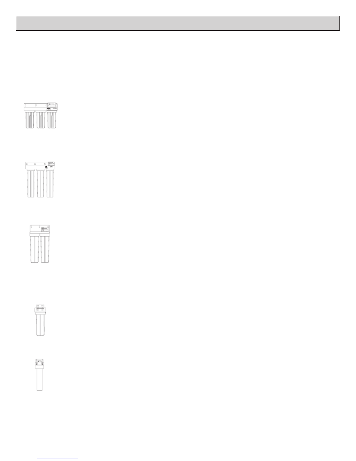
PURA SYSTEMS
PURA recommends that all UV systems include pre-lters to
process the water before it reaches the UV lamp. This will ensure
that maximum UV exposure is achieved.
PURA UVB, UV20 and UVBB series offers integrated lters in a
single system. These integrated systems use a two-stage ltration
process:
First, a string-wound lter removes the suspended solids that may
shield the microbes and make it difcult to obtain sufcient UV
exposure. Second, an activated carbon lter removes unpleasant
tastes and odors.
PURA Ultraviolet Water Treatment Systems are designed for indoor
use only.
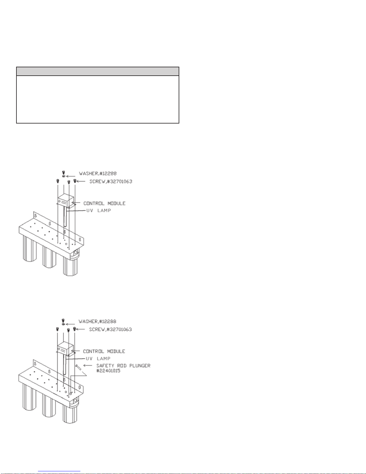
PURA Systems are designed to provide complete water treatment in
a compact, easy-to-use package. Please follow the directions in this
Guide exactly when installing your PURA System to ensure that it
operates correctly.
The UV lamp requires a start-up period of one to two minutes in
order to achieve full intensity. Repeated starting of the UV lamp
will shorten its life. Therefore, it is recommended that the UV lamp
remain on at all times during use.
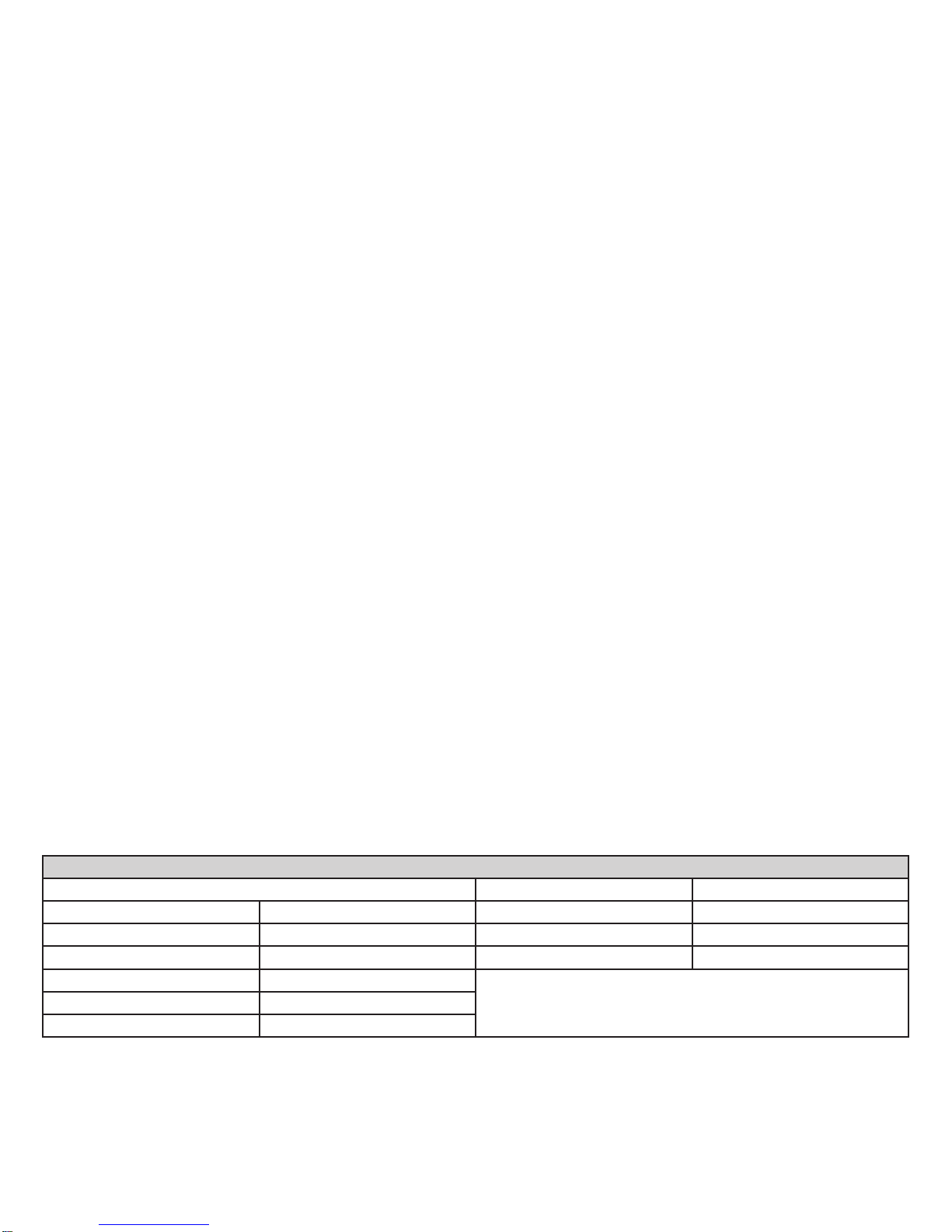
CONDITIONS FOR USE
Source Water Supply Prole Chemical Parameters Max mg/L
Feed Water Pressure† 20 – 75 psig (138 – 517 kPa) Hardness (CaCO3) < 120 (7 gpg)
Feed Water Temperature 38° – 105°F (3.3°– 40.5°C) Iron (Fe) < 0.3
pH Range 6.5 – 9.5 Manganese (Mn) < 0.05
Total Dissolved Solids <1500 mg/L † Water Pressure must not exceed 75 psig (517 kPa) or a pressure
regulator must be installed.
Total Suspended Solids < 10 mg/L
Turbidity < 5 NTU

ii
ROUTINE MAINTENANCE
It is important that any water treatment system be properly maintained to ensure consistent water quality. The information provided on this
page is of a general nature. See Cleaning, Disinfecting, and Routine Maintenance Procedure on Page 18 and 19 for detailed information.
Refer to Mounting Bracket and System Plumbing Installation Instructions on Page 1, and the appropriate System Assembly and Activation
Procedures for detailed information to install your specic PURA system.
Cleaning: The inside of the system and the quartz sleeve should be
cleaned each time the lters are changed. Clean all parts (except
the lters and electronic parts) with soap and rinse them thoroughly
with clean potable water. Dry the inside of the quartz sleeve
thoroughly before re-assembling system.
NOTE: Presence of iron or general poor water quality will
require frequent inspection and cleaning.
“O” Rings: Lubricate each “O” ring with a silicone based “O” ring
lubricant to ensure a proper seal.
NOTE: UV lamp should remain on at all times during use
because; repeated starting of UV lamp shortens lamp
life, and UV lamp requires a warm up period of 1-2
minutes.
Filter Replacement: Filters will normally last approximately four to
six months. Filter life will vary due to water conditions. A reduced
ow rate or deteriorating water quality indicates that lters must be
changed.
Use only PURA lters. PURA lters are specially designed to work
in the ultraviolet disinfection process. Use of non-PURA lters voids
the warranty.
CAUTION: Use care when changing the lters to avoid breaking
the quartz sleeve.
UV Lamp Replacement: Lamps must be changed every twelve
months. While UV lamps rarely burn out, they do lose their
disinfection power. Use only PURA UV lamps as they are specically
designed for the PURA system to deliver high quality drinking water.
PURA ULTRAVIOLET SPECIFICATIONS
Model Shipping
Weight
lbs. (kg)
Dimensions◊
Inches (Centimeters)
Height x Width x Depth
Flow Rate
Gallons Per Minute
Liters per Minute
Lamp Type &
Power Used
Watts Inlet/ Outlet
UVB1 10.0 lbs. (4.5 kg) 15.0” x 5.5” x 5.5”
(38.1 cm x 14.0 cm x 14.0 cm)
2 gpm (7.6 L/min) UV Lamp #11
14 Watts 3/8” NPT†
UVB2 15.0 lbs. (6.8 kg) 15.0” x 11.0” x 5.5”
(38.1 cm x 27.9 cm x 14.0 cm)
UVB3 24.0 lbs. (10.9 kg) 15.0” x 16.0” x 5.5”
(38.1 cm x 40.6 cm x 14.0 cm)
UV20-1 16.0 lbs. (7.3 kg) 25.0” x 5.5” x 5.5”
(63.5 cm x 14.0 cm x 14.0 cm) 10 gpm (38 L/min) UV Lamp #20
22 Watts 3/4” NPT†
UV20-2 24.0 lbs. (10.9 kg) 25.0” x 11.0” x 5.5”
(63.5 cm x 27.9 cm x 14.0 cm)
UV20-3 32.0 lbs. (14.5 kg) 25.0” x 16.0” x 5.5”
(63.5 cm x 40.6 cm x 14.0 cm) 8 gpm (30 L/min)
UVBB-1 20.0 lbs. (9.1 kg) 29.5” x 7.5” x 9.0”
(74.9 cm x 19.0 cm x 22.9 cm)
15 gpm (57 L/min) UV Lamp #20
22 Watts 1-1/2” NPT†
UVBB-2 35.0 lbs. (15.9 kg) 28.0” x 15.0” x 9.0”
(71.1 cm x 38.1 cm x 22.9 cm)
UVBB-3 53 lbs. (24.0 kg) 28.0” x 23.0” x 9.0”
(71.1 cm x 58.4 cm x 22.9 cm)
UV1 7.0 lbs. (3.2 kg) 13.5” x 5.0” x 5.0”
(34.3 cm x 12.7 cm x 12.7 cm) 1 gpm (3.8 L/min) UV Lamp #10
10 Watts 1/2” NPT†
UV A/O-1 5.0 lbs. (2.3 kg) 12.0” x 4.0” x 3.5”
(30.5 cm x 10.2 cm x 8.9 cm) 1 gpm (3.8 L/min) UV Lamp #10
10 Watts 3/8 QC‡
UV A/O-3 7.0 lbs. (3.2 kg) 22.5” x 4.0” x 3.5”
(57.2 cm x 10.2 cm x 8.9 cm) 3 gpm (11.4 L/min) UV Lamp #20
22 Watts
† Female thread as recognized by United Sates National Pipe Thread.
‡ Push-in Quick Connectors or Quick Connectors (QC).
◊ All dimensions of system do not include inlet/outlet piping connections and are rounded up to the nearest 1/2”.

1
WARNING: NEVER LOOK DIRECTLY AT A LIGHTED UV LAMP.
ULTRAVIOLET RAYS CAN BE HARMFUL TO EYES.
ALWAYS SHUT OFF WATER TO SYSTEM AND DISCONNECT POWER WHEN SERVICING.
ASSEMBLY IS REQUIRED BEFORE INSTALLATION. FRAGILE PARTS INSIDE.
FOLLOW INSTRUCTIONS CAREFULLY!
The system must be installed in accordance with applicable city, country, and local plumbing codes.
PURA products are designed to provide years of trouble-free service if properly maintained.
Retain these instructions for future reference.
MOUNTING BRACKET AND SYSTEM PLUMBING INSTALLATION
This Guide covers installation and maintenance of a basic “generic” system. Installer determines conguration of each system and must
adapt these instructions to meet the specic requirements for that conguration. Specic component and assembly information is provided
only for components that are unique to PURA systems. All inter-component connections use standard plumbing components and tools.
INSTALL MOUNTING BRACKET
CAUTION: Do not use any damaged component.
If damage is found, contact your dealer before
proceeding.
1. Unpack boxes and verify that all required components have been
received (see Preparation section for your particular series).
2. Inspect each component for damage.
3. Determine location for installation of the UV system:
a. The PURAUV System should be installed with the sumps
oriented vertically.
CAUTION: The UV system may be installed horizontally, but
the quartz sleeve will be in a position that makes it
susceptible to breakage.
b. Mounting point should allow sufcient room above and
below UV system to service the sumps and UV lamp
without removing the UV system.
The minimum space is:
UVB: 11” (above and below)
UV20, UVBB: 20” (above and below)
UV1: 10” (above and below)
ADDON: 10” or 20” (above) by model
4. For ease of mounting, reduce the weight of the larger systems
by removing the sumps and lters prior to installing the mounting
bracket.
5. Select a location and install the mounting bracket using the
provided screws.
INSTALL SYSTEM PLUMBING
CAUTION: Water pressure must not exceed 75 psig (517 kPa) or
a pressure regulator must be used.
CAUTION: Do not install pump on outlet side of system as
damage to the quartz sleeve may occur. If pump is
required, install it on inlet side of system and verify
output pressure does not exceed 75 psig (517 kPa).
CAUTION: Warranty is void if the unit is used with pressure
exceeding 75 psig (517 kPa). Higher pressures may
damage equipment and may not allow for proper
exposure time with UV lamp or both.
CAUTION: The system will not function properly if water ow is
reversed. See the Exploded Schematic for your model
on the following
1. Turn off source water supply.
CAUTION: PURA recommends using only plastic ttings to
connect the inlet and outlet ports of the PURA system.
Use of metal male ttings inside of plastic female
threaded heads voids the warranty.
CAUTION: Do not over tighten ttings connected to inlet/outlet
ports of the PURA system.
2. Connect inlet of UV system to source water supply using proper
ttings and thread sealing tape.
3. Connect outlet of UV system to water distribution lines using
proper ttings and thread sealing tape.
CAUTION: Do not install clear or translucent tubing on the outlet
side.
4. See appropriate System Assembly and Activation Procedures for
your system to complete installation.

2
UVB SERIES - SYSTEM ASSEMBLY AND ACTIVATION PROCEDURES
PREPARATION – INSPECT ALL PARTS
NOTE: Read Mounting Bracket and System Plumbing
Installation instructions on Page 1 and all instructions
on this page before installing system.
NOTE: See Page 4 for UVB detailed parts breakdown. Refer
to the label afxed to the mounting bracket to identify
lter(s) to be installed with UV module.
CONTROL MODULE INSTALLATION
CONTROL MODULE INSTALLATION WITH SAFETY ROD FOR
UVB MODELS WITHOUT THE LOC OPTION
INSTALL QUARTZ SLEEVE AND DISINFECT SYSTEM
Check page 20 for pictures of Quartz Sleeve.
CAUTION: QUARTZ SLEEVE IS VERY FRAGILE!
For safety, wear a protective glove when handling
quartz sleeve. Do not touch quartz sleeve or UV
lamp with bare hands. Fingerprints will reduce the
effectiveness of the light.
NOTE: All Items refer to Figure 1.
1. Remove Sump (Item 1) from UV Head (Item 5).
NOTE: Do not remove protective plastic bag from quartz
sleeve until so instructed.
2. Remove Quartz Sleeve (Item 17) from packing tube. While
holding middle of quartz sleeve with one hand, slide protective
bag with other hand to expose open end.
3. Place a small amount of silicone based “O” ring lubricant on the
outside of the open end of the quartz sleeve only on the area that
will engage with the “O” ring.
CAUTION: Apply even pressure to push the quartz sleeve into the
UV head. To avoid breakage, make sure quartz sleeve
goes in straight by pushing it with a slight twisting
motion.
4. Insert quartz sleeve into the UV head. As quartz sleeve passes
the “O” Ring (Item 15), resistance will be felt. Remove protective
bag from quartz sleeve.
5. Remove EPCB™ Carbon Filter (Item 3) and EPCB™ Sleeve
(Item 24) from sump and set aside.
6. For UVB2 and UVB3 Models only: Remove Sump (Item 1) from
Filter Head (Item 20). Remove Filters (Items 21 and 23) from
sump and set aside.
7. Disinfect the system (Pages 18-19, Steps 1-7).
INSTALL ULTRAVIOLET LIGHT AND FILTERS
1. Remove Sump (Item 1) from UV Head (Item 5).
NOTE: Wipe all ngerprints and excessive lubricant from
quartz sleeve with isopropyl alcohol.
2. Install EPCB™ Sleeve (Item 24) into EPCB™ Carbon Filter (Item
3) as shown in Figure 1.
3. Insert lter/sleeve assembly into sump as shown in Figure 1 with
both Filter Gaskets (Item 4) in place.
CAUTION: TIGHTEN SUMPS BY HAND ONLY. Do not use tools
as they will over-tighten and may damage sump. Take
care not to cut or pinch “O” Rings (Item 2). Use sump
wrench for removal only.
4. Being careful not to dislodge quartz sleeve, install sump with lter/
sleeve assembly onto UV head.
5. For UVB2 & UVB3 Models only: Remove Sump (Item 1) from
Filter Head (Item 20). Install Filters (Items 21 and 23) as shown in
Figure 1. Install sump onto lter head.
CAUTION: DO NOT INSTALL A DAMAGED LAMP
INSTALL CONTROL MODULE AND UV LAMP
NOTE: Hold UV lamp by ceramic ends only. Do not touch the
glass. Clean with isopropyl alcohol if necessary.
6. Remove UV Lamp (Item 16) from packing tube and inspect it for
damage. If damage is found, contact the dealer for a replacement.
UVB SERIES
UVB Ultraviolet System
Control Module Box
Ultraviolet Lamp #11 (in packing tube)
Quartz Sleeve #11 (in packing tube)
Mounting Screws (2-4 pieces, varies with model)
Installation Manual and Owners Guide
Sump Wrench #10/20
Figure 1A - * UVB-3 model shown
Figure 1B - * UVB-3 model shown

3
The UVB control module installation kit includes:
a. Control Module – Qty 1
b. Screws , 6/32 X 3/8” (Part# 32701063) - Qty 4
c. Washer, Lock , #8 (Part# 12288) - Qty 1
d. Safety Rod Plunger (Part # 22401015) – Qty 1 (ONLY FOR
SYSTEMS WITHOUT THE LAMP OUT CIRCUIT OPTION)
e. Installation Guide (#54752)
7. Unpack the carton box and verify that all the required components
have been received.
8. Connect UV lamp into four-pin socket located at the bottom of UV
Control Module (Item 10).
9. Verify Safety Plunger Rod (Item 18) is in place.
NOTE: System with Light-Out Circuit (LOC) does not have a
safety plunger rod.
10. Carefully insert the UV control module with UV lamp through
mounting bracket into the quartz sleeve.
11. Install the UVB control module on top of the ultraviolet
disinfection system’s bracket with four screws and one lock
washer (for grounding purpose) as shown in the Figure* 1A.
12. For UVB series ultraviolet disinfection systems without the
lamp out circuit (LOC) option, install the safety rod plunger as
shown in the Figure* 1B.
ACTIVATE SYSTEM
CAUTION: Verify that inlet and outlet ports are connected to
appropriate inlet/outlet pipes (see Figure 1).
1. Plug system into an electrical outlet. If the LED Indicator (Item 8)
does not light up within one minute, verify UV lamp is securely
plugged into UV control module and safety plunger rod is in place
(see Note in Step 9 above). It is normal for the LED indicator to
icker slightly.
NOTE: The UV lamp should remain on at all times during use
because; repeated starting of UV lamp shortens lamp
life, and UV lamp requires a warm up period of 1-2
minutes.
2. Turn on water supply and check for leaks.
3. Flush system, connectors, and water lines for several minutes to
remove carbon nes.
NOTE: When an ultraviolet water treatment system is unused
for several hours, water within system could become
warm. This is a dispense water from system.
NOTE: System is now ready for use.
Service Requirements Recommended Service Intervals
To ensure the system operates at its optimum level,
certain routine maintenance must be performed.
Frequency of maintenance performance will depend on
source water quality and level of system usage.
CLEAN: Each time lters are replaced.
DISINFECT: At least once a year.
UV Lamp #11: Change Annually
Quartz Sleeve #11: Clean when changing lters. Replace only if
damaged or cannot be cleaned by non-abrasive methods.
Filters: Normal life 4-6 months. Filter life will vary due to water
conditions. A reduced ow rate or deteriorating water quality
indicates that lters must be changed.

4
1Sump, #10 (“O” Ring, Sump #10/20
Head UV #10/20Assy) 92502
2 “O” Ring, Housing, UVB 92513
3 Filter, Carbon EPCB™ 10” 33004030
4 Gasket, c/w Filter -----
6 Mounting Bracket, 1 Sump 31910101
6A Mounting Bracket, 2 Sump 31910201
6B Mounting Bracket, 3 Sump 31910301
7 Switch, Safety -----
8 Indicator, LED -----
9 Fuse, 1AType 3AG 31000006
10 Module, UV Control #11 40200116†
11 Screw, 6/32 x 3/8” 32701063
12 Screw, #10 x 3/4” 32701006
13 Screw, 1/4” x 1-1/2” 32701061
14 Washer, #14 Nylon 32800031
15 “O” Ring, Quartz Sleeve, Standard 34202021
16 Lamp, UV #11 36002017
17 Sleeve Quartz #11 w/”O” Rings 36003034
18 Rod, Safety Plunger 22401015
19 Spacer, Bushing #10/20 22401016
20 Head, Filter 3/4” #10/20, “O” Ring,
Sump, Filter #10/20 92501
21 Filter, Sediment 10” 5 micron 33003051
22 Nipple, 3/4” 33601023
23 Filter, GC 10” 5 micron 33004024
24 Sleeve, Teon 30120506
25 Bushing, 3/4” x 3/8” 33300017
n/s‡ Wrench, Sump #10/20 92508
† Consult Factory to determine part number for applications other than 120V/60hz ‡ not shown
Figure 1 Exploded Schematic, PURA UVB Series
Parts List - UVB Series
Item Description Part No. Item Description Part No. Item Description Part No.

5
UV20 SERIES - SYSTEM ASSEMBLY AND ACTIVATION PROCEDURES
PREPARATION – INSPECT ALL PARTS
NOTE: Read Mounting Bracket and System Plumbing
Installation instructions on Page 1 and all instructions
on this page before installing system.
NOTE: See Page 7 for UV20 detailed parts breakdown. Refer
to the label afxed to the mounting bracket to identify
lter(s) to be installed with UV module.
CONTROL MODULE INSTALLATION
CONTROL MODULE INSTALLATION WITH SAFETY ROD FOR
UV20 MODELS WITHOUT THE LOC OPTION
INSTALL QUARTZ SLEEVE AND DISINFECT SYSTEM
Check page 20 for pictures of Quartz Sleeve.
CAUTION: QUARTZ SLEEVE IS VERY FRAGILE!
For safety, wear a protective glove when handling
quartz sleeve. Do not touch quartz sleeve or UV
lamp with bare hands. Fingerprints will reduce the
effectiveness of the light.
NOTE: All Items refer to Figure 1.
1. Remove Sump (Item 1) from UV Head (Item 5).
NOTE: Do not remove protective plastic bag from quartz
sleeve until so instructed.
2. Remove Quartz Sleeve (Item 17) from packing tube. While
holding middle of quartz sleeve with one hand, slide protective
bag with other hand to expose open end.
3. Place a small amount of silicone based “O” ring lubricant on the
outside of the open end of the quartz sleeve only on the area that
will engage with the “O” ring.
CAUTION: Apply even pressure to push the quartz sleeve into the
UV head. To avoid breakage, make sure quartz sleeve
goes in straight by pushing it with a slight twisting
motion.
4. Insert quartz sleeve into the UV head. As quartz sleeve passes
the “O” Ring (Item 15), resistance will be felt. Remove protective
bag from quartz sleeve.
5. For UV20-2 and UV20-3 Models only: Remove Sump (Item 1)
from Filter Head (Item 20). Remove Filters (Items 21 and 23) from
sump and set aside.
6. Disinfect the system (Pages 18-19, Steps 1-7).
INSTALL ULTRAVIOLET LIGHT AND FILTERS
1. Remove Sump (Item 1) from UV Head (Item 5).
NOTE: Wipe all ngerprints and excessive lubricant from
quartz sleeve with isopropyl alcohol.
2. Verify Stainless Steel Channeling Sleeve (Item 3) and Sleeve
Gasket (Item 4) are in sump as shown in Figure 2.
CAUTION: TIGHTEN SUMPS BY HAND ONLY. Do not use tools
as they will over-tighten and may damage sump. Take
care not to cut or pinch “O” Rings (Item 2). Use sump
wrench for removal only.
3. Being careful not to dislodge quartz sleeve, install sump with lter/
sleeve assembly onto UV head.
4. For UV20-2 & UV20-3 Models only: Remove Sump (Item 1) from
Filter Head (Item 20). Install Filters (Items 21 and 23) as shown in
Figure 1. Install sump onto lter head.
CAUTION: DO NOT INSTALL A DAMAGED LAMP
INSTALL CONTROL MODULE AND UV LAMP
NOTE: Hold UV lamp by ceramic ends only. Do not touch the
glass. Clean with isopropyl alcohol if necessary.
5. Remove UV Lamp (Item 16) from packing tube and inspect it for
damage. If damage is found, contact the dealer for a replacement.
UV20 SERIES
UV20 Ultraviolet System
Control Module Box
Ultraviolet Lamp #20 (in packing tube)
Quartz Sleeve #20 (in packing tube)
Mounting Screws (2-4 pieces, varies with model)
Installation Manual and Owners Guide
Sump Wrench #10/20
Figure 2A - * UV20-3 model shown
Figure 2B - * UV20-3 model shown

6
The UV20 control module installation kit includes:
a. Control Module – Qty 1
b. Screws , 6/32 X 3/8” (Part# 32701063) - Qty 4
c. Washer, Lock , #8 (Part# 12288) - Qty 1
d. Safety Rod Plunger (Part # 22401015) – Qty 1 (ONLY FOR
SYSTEMS WITHOUT THE LAMP OUT CIRCUIT OPTION)
e. Installation Guide (#54752)
6. Unpack the carton box and verify that all the required components
have been received.
7. Connect UV lamp into four-pin socket located at the bottom of UV
Control Module (Item 10).
8. Verify Safety Plunger Rod (Item 18) is in place.
NOTE: System with Light-Out Circuit (LOC) does not have a
safety plunger rod.
9. Carefully insert the UV control module with UV lamp through
mounting bracket into the quartz sleeve.
10. Install the UV20 control module on top of the ultraviolet
disinfection system’s bracket with four screws and one lock
washer (for grounding purpose) as shown in the Figure* 2A.
11. For UV20 series ultraviolet disinfection systems without the
lamp out circuit (LOC) option, install the safety rod plunger as
shown in the Figure* 2B
ACTIVATE SYSTEM
CAUTION: Verify that inlet and outlet ports are connected to
appropriate inlet/outlet pipes (see Figure 2).
1. Plug system into an electrical outlet. If the LED Indicator (Item 8)
does not light up within one minute, verify UV lamp is securely
plugged into UV control module and safety plunger rod is in place
(see Note in Step 8 above). It is normal for the LED indicator to
icker slightly.
NOTE: The UV lamp should remain on at all times during use
because; repeated starting of UV lamp shortens lamp
life, and UV lamp requires a warm up period of 1-2
minutes.
2. Turn on water supply and check for leaks.
3. Flush system, connectors, and water lines for several minutes to
remove carbon nes.
NOTE: When an ultraviolet water treatment system is unused
for several hours, water within system could become
warm. This is a dispense water from system.
NOTE: System is now ready for use.
Service Requirements Recommended Service Intervals
To ensure the system operates at its optimum level,
certain routine maintenance must be performed.
Frequency of maintenance performance will depend on
source water quality and level of system usage.
CLEAN: Each time lters are replaced.
DISINFECT: At least once a year.
UV Lamp #20: Change Annually
Quartz Sleeve #20 and Channeling Sleeve: Clean when changing
lters. Replace only if damaged or cannot be cleaned by non-
abrasive methods.
Filters: Normal life 4-6 months. Filter life will vary due to water
conditions. A reduced ow rate or deteriorating water quality
indicates that lters must be changed.

7
1Housing, UV, Sump, #20
(“O” Ring, Head UV #10/20) 92504
2 “O” Ring, Sump #10/20 92513
3 Sleeve, Channeling S/S, #20 44301007
4 Gasket, Sleeve 36099205
6 Mounting Bracket, 1 Sump 31910101
6A Mounting Bracket, 2 Sump 31910201
6B Mounting Bracket, 3 Sump 31910301
7 Switch, Safety -----
8 Indicator, LED -----
9 Fuse, 1AType 3AG 31000006
10 Module, UV Control #11 40200116†
11 Screw, 6/32 x 3/8” 32701063
12 Screw, #10 x 3/4” 32701006
13 Screw, 1/4” x 1-1/2” 32701061
14 Washer, #14 Nylon 32800031
15 “O” Ring, Quartz Sleeve, Standard 34202021
16 Lamp UV #20 36002018
17 Sleeve Quartz #20, with “O” Rings 36003035
18 Rod, Safety Plunger 22401015
19 Spacer, Bushing #10/20 22401016
20 Housing, Filter 3/4” #10/20, “O”
Ring, Sump, Head 92503
21 Filter, Sediment 20” 5 micron 33003033
22 Nipple, 3/4” 33601023
23 Filter, Carbon Block 20” EPM 10
micron 33004022
n/s‡ Wrench, Sump #10/20 92508
† Consult Factory to determine part number for applications other than 120V/60hz ‡ not shown
Figure 2 Exploded Schematic, PURA UV20 Series
Parts List - UV20 Series
Item Description Part No. Item Description Part No. Item Description Part No.

8
UVBB SERIES - SYSTEM ASSEMBLY AND ACTIVATION PROCEDURES
PREPARATION – INSPECT ALL PARTS
NOTE: Read Mounting Bracket and System Plumbing
Installation instructions on Page 1 and all instructions
on this page before installing system.
NOTE: See Page 10 for UVBB detailed parts breakdown.
Refer to label afxed to the mounting bracket to
identify lter(s) to be installed with UV module.
CONTROL MODULE INSTALLATION
INSTALL QUARTZ SLEEVE AND DISINFECT SYSTEM
Check page 20 for pictures of Quartz Sleeve.
CAUTION: QUARTZ SLEEVE IS VERY FRAGILE!
For safety, wear a protective glove when handling
quartz sleeve. Do not touch quartz sleeve or UV
lamp with bare hands. Fingerprints will reduce the
effectiveness of the light.
NOTE: All Items refer to Figure 3.
1. Remove Sump (Item 1) from UV Head (Item 5).
NOTE: A band of Red Tape (Item 23) is afxed to quartz
sleeve approximately 3” from the top. Do not remove
this tape until so instructed. Do not remove protective
plastic bag from quartz sleeve until so instructed.
2. Remove Quartz Sleeve (Item 17) from packing tube. While
holding middle of quartz sleeve with one hand, slide protective
bag with other hand to expose open end.
3. Place a small amount of silicone based “O” ring lubricant on the
outside of the open end of the quartz sleeve only on the area that
will engage with the “O” ring.
CAUTION: Apply even pressure to push the quartz sleeve into
Quartz Adapter Sleeve (Item 4). To avoid breakage,
make sure quartz sleeve goes in straight by pushing it
with a slight twisting motion.
4. Insert quartz sleeve into quartz adapter sleeve until the top of red
tape meets the bottom of the quartz adapter sleeve.
NOTE: Quartz Adapter Sleeve (Item 4) is factory installed into
the UV Head (Item 5).
5. Remove Red Tape (Item 23) and protective bag from quartz
sleeve.
NOTE: Wipe all ngerprints and excessive lubricant from
quartz sleeve with isopropyl alcohol.
6. For UVBB-2 and UVBB-3 Models only: Remove Sump (Item 1)
from Filter Head (Item 20). Remove Filters (Items 21 and 22) from
sump and set aside.
7. Disinfect the system (Pages 18-19, Steps 1-7).
INSTALL ULTRAVIOLET LIGHT AND FILTERS
CAUTION: TIGHTEN SUMPS BY HAND ONLY. Do not use tools
as they will over-tighten and may damage sump. Take
care not to cut or pinch “O” Rings (Item 2). Use sump
wrench for removal only.
8. For UVBB-2 and UVBB-3 Models only: Remove Sump (Item
1) from Filter Head (Item 20). Install Filters (Items 21 and 22) as
shown in Figure 3. Install sump onto lter head.
CAUTION: DO NOT INSTALL A DAMAGED LAMP
INSTALL CONTROL MODULE AND UV LAMP
NOTE: Hold UV lamp by ceramic ends only. Do not touch the
glass. Clean with isopropyl alcohol if necessary.
9. Remove UV Lamp (Item 16) from packing tube and inspect it for
damage. If damage is found, contact the dealer for a replacement.
10. Unpack the carton box and verify that all the required
components have been received.
The UVBB control module installation kit includes:
a) Control Module – Qty 1
b) Screws , 6/32 X 3/8” (Part# 32701063) - Qty 4
c) Washer, Lock , #8 (Part# 12288) - Qty 1
d) Installation Guide (#54752)
11. Connect UV lamp into four-pin socket that is connected to the
UV control module by a cable that allows for correct insertion
depth.
12. Carefully insert the UV control module with UV lamp through
mounting bracket into the quartz sleeve making sure the cable
does not twist or curl.
13. Install the UVBB control module on top of the ultraviolet
disinfection system’s bracket with four screws and one lock
washer (for grounding purpose) as shown in the Figure* 3A.
UVBB SERIES
UVBB Ultraviolet System
Control Module Box
Ultraviolet Lamp #20 (in packing tube)
Quartz Sleeve #22 (in packing tube)
Mounting Screws (2-4 pieces, varies with model)
Installation Manual and Owners Guide
Sump Wrench #20BB
Figure 3A - * UVBB-3 model shown

9
ACTIVATE SYSTEM
CAUTION: Verify that inlet and outlet ports are connected to
appropriate inlet/outlet pipes (see Figure 3).
1. Plug system into an electrical outlet. If the LED Indicator (Item 8)
does not light up within one minute, verify UV lamp is securely
plugged into UV control module. It is normal for the LED indicator
to icker slightly.
NOTE: The UV lamp should remain on at all times during use
because; repeated starting of UV lamp shortens lamp
life, and UV lamp requires a warm up period of 1-2
minutes.
2. Turn on water supply and check for leaks.
3. Flush system, connectors, and water lines for several minutes to
remove carbon nes.
NOTE: When an ultraviolet water treatment system is unused
for several hours, water within system could become
warm. This is a normal condition. To cool the water,
dispense water from system.
NOTE: System is now ready for use.
Service Requirements Recommended Service Intervals
To ensure the system operates at its optimum level,
certain routine maintenance must be performed.
Frequency of maintenance performance will depend on
source water quality and level of system usage.
CLEAN: Each time lters are replaced.
DISINFECT: At least once a year.
UV Lamp #20: Change Annually
Quartz Sleeve #20: Clean when changing lters. Replace only if
damaged or cannot be cleaned by non-abrasive methods.
Filters: Normal life 4-6 months. Filter life will vary due to water
conditions. A reduced ow rate or deteriorating water quality
indicates that lters must be changed.

10
1
Sump, UV #20 BB (“O” Ring, Sump
BB, Head UV #20 BB,Assy - 3
pieces) includes #18 SS Sleeve
#92724
92721SS
2 “O” Ring, Housing, BB 92722
3Sleeve, Teon, Delivery BB c/w
clamp 44301015
4Sleeve, QuartzAdapter with “O”
Rings 44301009
n/s‡ “O” Ring, QuartzAdapter Sleeve
Inner (2 pieces) 34202022
n/s‡ “O” Ring, QuartzAdapter Sleeve
Outer (2 pieces) 34201039
6 Mounting Bracket, 1 Sump BB 31910102
6A Mounting Bracket, 2 Sump BB 31910202
6B Mounting Bracket, 3 Sump BB 31910302
7 Switch, Safety -----
8 Indicator, LED -----
9 Fuse, 1AType 3AG 31000006
10 Module, UV Control BB 44302403†
11 Screw, 6/32 x 3/8” 32701063
12 Screw, #14 x 1” 32701060
13 Screw, 5/16 x 1-1/4” 32701074
14 Washer, 5/16” 32800029
15 “O” Ring, Quartz Sleeve BB 34202022
16 Lamp, UV #20 36002018
17 Sleeve, Quartz #22 with “O” Rings 36003036
18 Sleeve, BB, #20, S/S 92724
19 Nipple, 1-1/2” 33601024
20 Head, Filter 1-1/2” BB (Sump,
UV#20 BB, Filter “O” Ring, Sump
BB, Filter - 3 pieces) 92720
21 Filter, Sediment 20” 5 micron BB 33003117
22 Filter, Carbon Block 20” 10 micron
BB, EPM 33004015
n/s‡ Wrench, Sump #20 BB 92723
23 Red Tape -----
† Consult Factory to determine part number for applications other than 120V/60hz ‡ not shown
Figure 3 Exploded Schematic, PURA UVBB Series
Parts List - UVBB Series
Item Description Part No. Item Description Part No. Item Description Part No.

11
RACK SYSTEM - SYSTEM ASSEMBLY AND ACTIVATION PROCEDURES
PREPARATION – INSPECT ALL PARTS
NOTE: Read Assembly and Installation instructions on this
page and UVBB System Installation and Activation
Procedures on Pages 8-9 before assembling Rack
System
.
† Per UV Control Module as specied for applicable conguration.
NOTE: See Page 10 for UVBB detailed parts breakdown.
Refer to the label afxed to the UVBB mounting
bracket to identify housing units to be installed on
rack.
*Filters Sold Separately.
RACK ASSEMBLY
NOTE: Items in this section refer to Figure 4.
CAUTION: Maximum load for the Rack System is 750 lbs. (340
kg). This system is designed for indoor use only.
NOTE: Each UVBB-1 housing assembly can process up
to 15 gpm (57 L/min). Up to four assemblies may
be installed on the Rack System. Four housing
assemblies may be plumbed in parallel (See Figure 6)
to obtain a maximum ow of 60 gpm (227 L/min).
NOTE: Each attachment point requires a Bolt (Item 8), two
Flat Washers (Item 7), and a Nut (Item 6).
1. Attach the Feet (Item 1) to the bottom of each Leg (Item 2).
NOTE: Snug, but do not tighten the bolts and nuts connecting
the legs and top to the Corner Braces (Item 4) until
assembly has been squared.
2. Attach two corner braces to the upper end of each leg.
3. Attach the Leg Brace (Item 3) to the back of each leg.
4. Attach the Top (Item 5) to the corner braces.
5. Square top to the legs. Tighten all 16 nuts securing corner braces.
INSTALL UV SYSTEM TO RACK
NOTE: Items in this section refer to Figure 5
NOTE: Figures 5 and 6 provide examples of congurations
that may be applied to your PURA system. These
congurations are not intended as a representation of
a specic system to be installed.
1. Determine location for installation of the Rack System with
housing assemblies. Three requirements for consideration are:
access to cold water line, access to power, and proper inlet/outlet
connection for each housing assembly.
NOTE: Each UV control module has its own cord. A power
strip may be required if multiple UV control modules
are installed on Rack System.
2. Install the Rack System. Unit may be attached to surface or left
freestanding.
3. Secure each Mounting Adapter Plate (Item 11) and UV head to
Rack System with Lag Bolts (Item 10) and Flat Washers (Item 9).
NOTE: To install a system in “SERIES” as shown in Figure
5, connect all heads together with nipples prior to
installing heads on Rack System.
4. Plumb heads for specic conguration using proper ttings and
thread sealing tape.
NOTE: See Pages 8-9 for UVBB Assembly and Activation
Procedures to complete installation.
Figure 4 Rack Components and Location
Parts List - UVBB Series
Item Description Quantity
1 Feet (18” / 46cm deep) 2
2 Legs (42” / 107cm high) 2
3 Leg Brace (34-1/4” / 87cm wide) 1
4 Corner Braces 4
5 Top (34-1/4” / 87cm wide) 1
6 Lock Nut, 1/4 – 20 22
7 Flat Washer, 1/4" 44
8 Hex Bolt, 1/4 – 20 x 1” 22
9 Flat Washer, 5/16” 16
10 Lag Bolt, 5/16 x 1–1/4" 16
11 MountingAdapter Plate 1†
12 Screw, 6/32 x 3/8” 4†
13 Kit, Sleeve, Screw, Washer #92620 1

12
Figure 5 Module Attachment Points Figure 6 UVBB Rack System Congurations
Table 1 System Conguration and Component Parts, Initial Installation
DATE INSTALLED SYSTEM OUTPUT RATING LPM/GPM
CONFIGURATION: SERIES SERIES TO PARALLEL PARALLEL PARALLEL TO SERIES
MODULE #1 TYPE PURA PART NUMBER:
MODULE #2 TYPE PURA PART NUMBER:
MODULE #3 TYPE PURA PART NUMBER:
MODULE #4 TYPE PURA PART NUMBER:

13
UV1 SERIES - SYSTEM ASSEMBLY AND ACTIVATION PROCEDURES
PREPARATION – INSPECT ALL PARTS
NOTE: Read Mounting Bracket and System Plumbing
Installation instructions on Page 1 and all instructions
on this page before installing system.
NOTE: See Page 14 for UV1 detailed parts breakdown. Refer
to label afxed to mounting bracket to identify lter to
be installed.
DISINFECT SYSTEM
CAUTION: QUARTZ SLEEVE IS VERY FRAGILE!
For safety, wear a protective glove when handling
quartz sleeve. Do not touch quartz sleeve or UV
lamp with bare hands. Fingerprints will reduce the
effectiveness of the light.
NOTE: Sump wrench not included.
NOTE: Quartz sleeve (Item 14) is factory installed.
NOTE: All Item callouts refer to Figure 7.
1. Remove Sump (Item 1) from UV Head (Item 5).
2. Remove EPCB™ Carbon Filter (Item 3) and EPCB™ Sleeve
(Item 15) from sump and set aside.
3. Disinfect the system (Pages 18-19, Steps 1-7).
INSTALL ULTRAVIOLET LIGHT AND FILTERS
1. Remove Sump (Item 1) from UV Head (Item 5).
NOTE: Wipe all ngerprints and excessive lubricant from
quartz sleeve with isopropyl alcohol.
2. Install EPCB™ Sleeve (Item 15) into EPCB™ Carbon Filter (Item
3) as shown in Figure 7.
3. Insert lter/sleeve assembly into sump as shown in Figure 7 with
both Filter Gaskets (Item 4) in place.
CAUTION: TIGHTEN SUMPS BY HAND ONLY. Do not use tools
as they will over-tighten and may damage sump. Take
care not to cut or pinch “O” Rings (Item 2).
4. Being careful not to dislodge quartz sleeve, install sump with lter/
sleeve assembly onto UV head.
5. Loosen Screw (Item 9) securing slotted side of UV Lamp Retainer
(Item 7). Remove the other screw securing the UV lamp retainer
to UV head. Rotate UV lamp retainer away from center of UV
head.
CAUTION: DO NOT INSTALLA DAMAGED LAMP
NOTE: Hold UV lamp by ceramic ends only. Do not touch the
glass. Clean glass with isopropyl alcohol if necessary.
6. Remove the UV Lamp (Item 17) from packing tube and inspect
it for damage. If damage is found, contact the dealer for a
replacement.
7. Connect UV lamp into the four-pin socket that is connected to the
UV Control (Item 11).
8. Carefully insert the UV lamp through mounting bracket into the
quartz sleeve as far as possible.
NOTE: End of UV lamp will touch bottom of quartz sleeve.
9. Slide Finish Cap (Item 13) on UV control cable and snap nish
cap into Spacer Bushing (Item 12).
10. Rotate UV lamp retainer towards UV lamp such that the retainer
will secure the UV lamp. Replace the screw removed in Step 5.
Tighten screw loosened in Step 5.
ACTIVATE SYSTEM
CAUTION: Verify that inlet and outlet ports are connected to
appropriate inlet/outlet pipes (see Figure 7).
WARNING: NEVER LOOK DIRECTLY ATA LIGHTED UV LAMP.
ALWAYS LOOK AT LAMP THROUGH FINISH CAP
ONLY.
1. Plug system into an electrical outlet. The nish cap should
illuminate within one minute, indicating UV lamp is on. If it does
not, unplug system, verify the UV lamp is securely plugged into
four-pin socket, and repeat this Step.
NOTE: UV lamp should remain on at all times during use
because; repeated starting of UV lamp shortens lamp
life, and UV lamp requires a warm up period of 1-2
minutes.
2. Turn on water supply and check for leaks.
3. Flush system, connectors, and water lines for several minutes to
remove carbon nes.
NOTE: When an ultraviolet water treatment system is unused
for several hours, water within system could become
warm. This is a normal condition. To cool the water,
dispense water from system.
NOTE: System is now ready for use.
UV1 SERIES
UV1 Ultraviolet System
Ultraviolet Lamp #10 (in packing tube)
Mounting Screws (2 pieces)
Installation Manual and Owners Guide
Service Requirements Recommended Service Intervals
To ensure the system operates at its optimum level,
certain routine maintenance must be performed.
Frequency of maintenance performance will depend on
source water quality and level of system usage.
CLEAN: Each time lters are replaced.
DISINFECT: At least once a year.
UV Lamp #10: Change Annually
Quartz Sleeve #10: Clean when changing lters. Replace only if
damaged or cannot be cleaned by non-abrasive methods.
Filters: Normal life 4-6 months. Filter life will vary due to water
conditions. A reduced ow rate or deteriorating water quality
indicates that lters must be changed.

14
1 Housing, UV1, Pura* 92500-1
2 “O” Ring, UV1, Pura 92060
3Filter, Carbon EPCB 10” 33004030
4 Gasket, c/w Filter -----
5 Spacer, UV1, Pura 32701010
6 Mounting Bracket, UV1, Pura 31910107
7 Retainer, UV Lamp UV1 31910408
8 Washer, #14 Nylon 32800031
9 Screw, #10-16 x 1" 32701007
10 Screw, #10 x 3/4" 32701006
11 UV Control, with Finish Cap 40200080†
12 Bushing, Spacer #10 SL 22401017
13 Cap, Finish, c/w Control -----
14 Sleeve, Quartz #10 with “O” Rings 36003033
15 Sleeve, Teon 30120506
16 “O” Ring Quartz Sleeve UV1 34202020
17 Lamp, UV #10 36002016
† Consult Factory to determine part number for applications other than 120V/60hz ‡ not shown
*92500-1 includes Items 1, 2, 5, 8, 9 &16.
Figure 7 Exploded Schematic, PURA UV1 Series
Parts List - UV1 Series
Item Description Part No. Item Description Part No. Item Description Part No.

15
ADDON SERIES - SYSTEM ASSEMBLY AND ACTIVATION PROCEDURES
PREPARATION – INSPECT ALL PARTS
NOTE: Read Mounting Bracket and System Plumbing
Installation instructions on Page 1 and all instructions
on this page before installing system.
NOTE: See Page 17 for ADDON detailed parts breakdown
INSTALL QUARTZ SLEEVE (ONLY FOR 3GPM MODEL)
NOTE: Quartz sleeve (Item 13) is factory installed for the
1 GPM model only.
NOTE: All Items refer to Figure 3.
NOTE: QUARTZ SLEEVE IS VERY FRAGILE!
For safety, wear a protective glove when handling
quartz sleeve. Do not touch quartz sleeve or UV
lamp with bare hands. Fingerprints will reduce the
effectiveness of the light.
1. Remove Collar (Item 15) from UV Head (Item 5A).
NOTE: Do not remove protective plastic bag from quartz
sleeve until so instructed.
2. Remove Quartz Sleeve (Item 13A) from packing tube. While
holding middle of quartz sleeve with one hand, slide protective
bag with other hand to expose open end.
3. Place a small amount of silicone based “O” ring lubricant on the
outside of the open end of the quartz sleeve only on the area that
will engage with the “O” ring.
CAUTION: Apply even pressure to push the quartz sleeve into
the UV head. To avoid breakage, make sure quartz
sleeve goes in straight by pushing it with slight twisting
motion.
4. Insert quartz sleeve into the UV head. As quartz sleeve passes
the “O” Ring (Item 9), resistance will be felt. Remove protective
bag from quartz sleeve.
DISINFECT SYSTEM
CAUTION: TIGHTEN COLLAR BY HAND ONLY. Do not use tools
as they will over-tighten and may damage sump. Take
care not to cut or pinch Addon Sump Gasket (Item 2).
1. For ADDON 1GPM Model Only: Remove Collar (Item 15) from
UV Head (Item 5).
NOTE: Wipe all ngerprints and excessive lubricant from
quartz sleeve with isopropyl alcohol.
2. Disinfect the system (Pages 18-19, Steps 1-7).
INSTALL ULTRAVIOLET LIGHT
CAUTION: DO NOT INSTALLA DAMAGED LAMP
NOTE: Hold UV lamp by ceramic ends only. Do not touch the
glass. Clean glass with isopropyl alcohol if necessary.
1. Remove the UV Lamp (Item 16 or 16A) from packing tube and
inspect it for damage. If damage is found, contact the dealer for a
replacement.
2. Connect UV lamp into the four-pin socket that is connected to the
UV Control (Item 10).
3. Carefully insert the UV lamp through “O” Ring Retainer (Item 11)
into the quartz sleeve as far as possible.
NOTE: End of UV lamp will touch the bottom of quartz sleeve.
4. Slide Finish Cap (Item 12) on UV control cable and snap nish
cap into “O” Ring Retainer (Item 11).
INSTALL TUBING
PLASTIC TUBING
1. Cut tube ends square and straight. Do not deform tube (i.e.,
cause tube to compress its diameter so it is no longer round).
2. Make sure outer surface of tube is clear of marks or scratches for
a length equal to twice tube diameter. This allows “O” rings to seat
properly against tube.
3. Avoid sharp changes in direction when routing tubing. Sharp turns
case tubing to ex and deform which reduces ow capacity and
may increase lateral stress on the ttings, causing leakage.
ADDON SERIES
Addon Ultraviolet System
Ultraviolet Lamp (in packing tube, #10 or #20 varies with model)
Quartz Sleeve (in packing tube, only for #20, 3GPM Model)
Mounting Screws (2 pieces)
Installation Manual and Owners Guide
This manual suits for next models
11
Table of contents
Other Pura Water Filtration System manuals
Popular Water Filtration System manuals by other brands

UV Pure Technologies
UV Pure Technologies Hallett instructions

Eaton
Eaton DWF 1505 Operation and maintenance manual

Pontec
Pontec PondoAir Set 1200 LED operating instructions

EHEIM
EHEIM LiBERTY Series operating instructions

Sera
Sera UV-C-System Assembly instruction

Jandy
Jandy AquaPure APURE700 Installation and operation manual