Much More Water BlueBox 4000 RO User manual

PURE WATER – ANYTIME – ANYWHERE
BlueBox 4000 RO
Manual
Applies to the Standard and Military version

PURE WATER – ANYTIME – ANYWHERE
BlueBox 4000 RO
Production line

BlueBox 4000 RO
CONTENTS
Safety regulations _________________________________________________________4
General__________________________________________________________________7
Data ____________________________________________________________________8
General _____________________________________________________________________ 8
Pump _______________________________________________________________________ 8
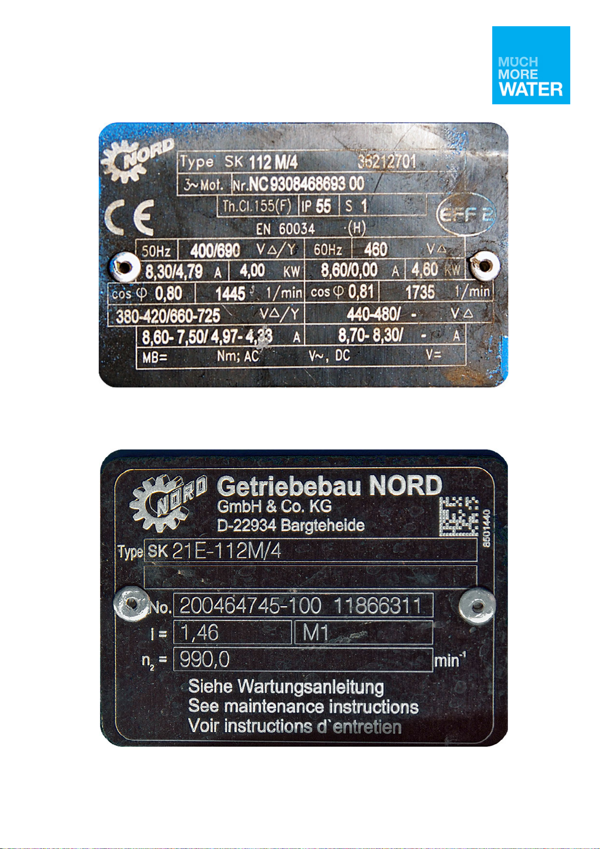
Electric motor ________________________________________________________________ 8
Purification system ____________________________________________________________ 8
Design and function ______________________________________________________10
General ____________________________________________________________________ 11
Accessories__________________________________________________________________ 13
Function, purification process __________________________________________________ 14
Pump unit __________________________________________________________________ 15
Control cabinet ______________________________________________________________ 17
Purification system ___________________________________________________________ 20
Operation _______________________________________________________________28
Installation and connection ____________________________________________________ 29
Start _______________________________________________________________________ 31
Stop _______________________________________________________________________ 33
Post-chlorination_____________________________________________________________ 33
Disconnection _______________________________________________________________ 34
Prior to short-term storage, danger of freezing ____________________________________ 35
Startup of spirit-filled water purifier ____________________________________________ 37
Cleaning with RoCide _________________________________________________________ 38
Cleaning, complete ___________________________________________________________ 39
Care ___________________________________________________________________41
General Maintenance ________________________________________________________ 42
Daily Inspection _____________________________________________________________ 43
Special supervision ___________________________________________________________ 45
Troubleshooting _____________________________________________________________ 50

4
Safety regulations
WARNING
The water purifier contains ESD sensitive equipment. Repairs to the water purifier’s
electrical system must only be carried out by a qualified electrician. Risk of damage to
the electrical system.
WARNING
Do not stand behind/in front of the water purifier when loading. Risk of injury.
WARNING
Observe the utmost cleanliness when working with the water purifier. Contaminated
drinking water involves high risk of transmission of diseases.
WARNING
It is important that the hoses are not connected to the wrong outlets on the water
purifier. ollow the colour markings. Risk of contamination of fresh water resulting in
diseases.
WARNING
Check that the power source to be used is equipped with a 30 mA residual current
device before the electric cable is connected to the water purifier.
WARNING
The water purifier’s electrical equipment can interfere with radio receivers. The water
purifier should be located 200–300 metres from the communications equipment when
the purifier is in operation.
WARNING
The light from the UV lamp can be harmful to the eyes. Therefore, never look directly
into the UV light.

5
WARNING
The water that comes out of the red wastewater hose must not be drunk or reused.
Serious risk of spread of diseases.
WARNING
Ethanol is a health and environmental hazard. Carefully follow the safety instruction
marked on the packaging.
WARNING
Ethanol is highly flammable. Smoking and the introduction of an open flame must not
occur during the handling of Ethanol. Risk of injury.
WARNING
A complete cleaning of the water purifier should be carried out once a month and if it
has not been used for more than 14 days.
WARNING
Carefully follow the safety instructions marked on the detergent’s original packaging.
The product is highly corrosive. Wear eye protection and protective gloves.
WARNING
The water purifier is used for purification of drinking water. It is therefore important
that the health measures are carried out correctly. If the purification of the water does
not work there is a risk of spread of diseases.
WARNING
Wear protective gloves when handling used filters. Risk of diseases.
NB:
The UV purifier contains glass. Handle the water purifier in such a way as to avoid
strong impact.
NB:
The water purifier must only be operated by staff trained to operate the equipment.
NB:

6
The water purifier must be adequately protected in accordance with prevailing weather
conditions.
NB:
The water purifier may not be used at temperatures below 5 °C. or information on
dangers of freezing, see section Daily inspection.
NB:
Avoid placing the water purifier in direct sunlight as excessive heat can affect the
electronics in the control cabinet.
NB:
During operation, check regularly on the UV purifier’s panel that the UV lamp is
working.
NB:
Drinking water out of the blue hose can be drunk only after the water purifier has been
running for 5 minutes.
NB:
Do not leave the drainage valves for the osmosis unit in the open position, risk of the
osmosis membrane drying out.
NB:
The osmosis membrane can freeze despite spirit treatment if the equipment is exposed
to extreme cold. This will not damage the membranes if they get to thaw at room
temperature. Do not thaw the membranes with other heat sources.
NB:
Never spray water directly on electrical equipment.
NB:
Do not squeeze or twist the filter bag in order to remove remaining water.
NB:
Comply with applicable waste regulations regarding the handling of used filters.
NB:
The filter inserts for particle filter 5 µm and carbon filter must not be cleaned, they
must be replaced.

7
General
Water purifier osmosis 4000 /T is intended to be used for the purification of polluted
water where access to fresh drinking water is in short supply. The equipment consists
mainly of:
•two plastic boxes with lids, containing the purifier and:
-one pump unit (pump and electric motor)
-one floating filter, two particle filters and two carbon filters
-twelve series-connected reverse osmosis membranes
-one UV purifier
-accessories including a suction hose.
Figure 1. Water purifier osmosis 4000 /T

8
Data
General
Stores title
BlueBox4000, Military version
Make and t pe Modified PureH2O A/S, BlueBox 4000
Purification capacit 4000 l/h (temperature dependent)
Dimensions, box 1(2) 1 200 × 1 155 × 1132 mm
Dimensions, box 2(2) 1 200 × 1 155 × 1132 mm
Weight, box 1(2) approx. 360 kg
Weight, box 2(2) approx. 270 kg
Voltage 400 V 50 Hz, three-phase
Operating temperature range 0 °C and above
Power intake CEE 16 A
Pump
T pe Self-priming triple membrane pump
Flow capacit 5,000 litre/h
Working pressure 8 bar
Maximum suction height 5m
Electric motor
Speed 990 r/min
Rated voltage Depending on the chosen connection
method, see igure 4, page 12
Rated current Depending on the chosen connection
method, see igure 4, page 12
Effect Depending on the chosen connection
method, see igure 4, page 12
Purification s stem
Pre-filter
Floating filter 100 µm
Particle filter 25 µm
Particle filter 5 µm
Active carbon filter
Reverse osmosis membrane
UV purifier

9
Figure 2. Product label on the electric motor
Figure 3. Product label on the pump gear

10
Figure 4. Product label on the control cabinet
Figure 5. ndividual marking on the inside of the boxes
Design and function

11
General
Water purifier osmosis 4000 /T is mounted in two shock-resistant and weatherproof
plastic boxes with removable lids. The boxes are designed so that they can be lifted
with pallet forks.
Both boxes have dry air supply, drainage at the bottom and hinged doors for easier
access to the water purification plant.
1Carbon filter 5 Hinged door
2UV purifier 6 Box 1
3Control cabinet 7 Particle filter 25 µm
4Pump unit 8 Particle filter 5 µm
Figure 6. Water purifier osmosis 4000, box 1

12
Figure 7. Water purifier osmosis 4000, box 2
Figure 8. Dry air connection
1 Osmosis unit
2Hinged door
3Box 2

13
Figure 9. Drainage
Accessories
The water purifier’s accessories to be stored in box 2.

14
Function, purification process
The pump sucks in water through the floating filter. It is then pumped through the four
pre-filters (two particle and two carbon filters) where it is cleansed of particles and
organic substances. After the pre-filters the water is led into the osmosis unit, which
has three circuits, separated by a membrane. When the pressure control valve is
turned clockwise this creates a counter pressure which pushes water toward the
membrane. The membranes are semipermeable and release virtually only water
molecules. The clean water flows on through the UV purifier, via a flow meter and out
through the fresh water hose. The dirty water is discharged via the osmosis unit’s
second circuit and out through the wastewater hose.
Figure 10. Purification process at 8 bar pressure

15
Pump unit
The pump unit consists of a triple diaphragm pump and a directly connected three-
phase electric motor. The pump unit sits on a rubber-mounted frame. The pump is self-
priming and does not need to be filled with water before starting.
On the pump’s pressure side is a pressure damper. The damper consists of a plastic
housing that contains a membrane. On the top of the housing is a filler nipple for air.
The pressure damper must be filled with 1–3 bar air pressure to dampen a water
pressure of 3–15 bar.
The pump is fitted with a safety valve that opens at 12 bar pressure.
1Pump
2 Pressure damper
3 Safet valve
4 Electric motor
Figure 11. Pump unit

16
The pump has two lubricator nipples for grease lubrication of the pump journal
bearings. One lubricator nipple is to be accessed from the front of the box via a plug in
the box.
Figure 12. Hole for lubricator nipple
The other lubricator nipple is positioned just in front of the cover over the pump shaft.
Figure 13. Pump shaft lubricator nipple

17
Control cabinet
WARNING
The water purifier contains ESD sensitive equipment. Repairs to the water purifier’s
electrical system must only be carried out by a qualified electrician. Risk of damage the
electrical system.
The control cabinet is bolted to the inner wall of box 1. The cabinet has two opening
doors. On the outside of the right door is a main power switch and two control buttons,
Start and Stop, with which to start and stop the pump.
Figure 14. Control cabinet
Behind the right door there are fuses and motor protection for the water purifier.
Behind the left door of the control cabinet is an operating time counter, and a power
supply unit for the UV purifier. When the UV lamp has been lit for a total of one year,
an alarm sounds as a reminder that the lamp should be replaced.
1Operating time counter 4 Fuse UV purifier
2Fuses 5 Reset button, lamp replacement
3Motor guard 6 Reset button, alarm
Figure 15. Control cabinet, interior

18
UV purifier’s monitoring panel
On the UV purifier’s power supply unit is a monitoring panel. The monitoring panel
indicates the operation of the UV lamp using various LEDs, see table 1, page 23.
By pressing the reset button A, igure 18, the alarm signal is temporarily disconnected.
The alarm sounds again after seven days. This procedure can be repeated four times
(total 28 days). After four resets the alarm will sound continuously until the lamp is
replaced and the time counter is reset.
The UV lamp’s time counter is reset by keeping the button for lamp replacement B
pressed in until a beep sounds for five seconds.
A Button for resetting the alarm 1 Indicator power suppl
B Button for resetting on lamp replacement
2Indicator fan
3 Indicator UV lamp
Figure 16. UV lamp’s monitoring panel

19
Table 1. ndicators on UV lamp’s panel
No Green Yellow Flashing
red
Permanent
red
1 Normal
operation
- ault in power
supply unit
- replace unit
Inactive due to
faulty lamp
- replace lamp
2 Normal
operation
The fan is
disconnected –
connect the fan
The fan runs
too slowly –
clean the fan
blades
The fan is
faulty – replace
fan
3 Normal
operation
( lashes during
heating)
Warning
The lamp needs
to be replaced
soon
The lamp is
disconnected –
disconnect the
power supply,
reconnect the
lamp and
connect the
power supply
again.
Lamp inactive
due to failure
of power supply
unit
The lamp is
faulty – replace
lamp.

20
Purification s stem
Floating filter
The floating filter sits at one end of the suction hose and has the task of filtering out
impurities down to 100 µm before the water reaches the pump. The floating filter
consists mainly of a steel wire strainer, two plastic grilles and a float. The float must be
filled with water to adjust the flow depth.
Figure 17. Floating filter
Particle filter 25 µm
Particle filter 25 µm consists of a filter container of steel containing a filter bag. The
particle filter purifies the water of particles down to 25 µm. The filter bag and filter
container can be cleaned by rinsing with clean water. If necessary, the filter bag
should be replaced.
Figure 18. Particle filter 25 µm
Table of contents
Other Much More Water Water Filtration System manuals
Popular Water Filtration System manuals by other brands

Atlantic Ultraviolet
Atlantic Ultraviolet Mighty Pure MP16A owner's manual

SunSun
SunSun CBG-500 Operation manual

Hayward
Hayward XStream Filtration Series owner's manual

Contech
Contech DownSpout StormFilter Operation and maintenance

Teka
Teka Airfilter MINI operating instructions

Wisy
Wisy LineAir 100 Installation and operating instructions

Schaffner
Schaffner Ecosine FN3446 Series User and installation manual

Pentair
Pentair FLECK 4600 SXT Installer manual

H2O International
H2O International H20-500 product manual

Renkforce
Renkforce 2306241 operating instructions

Neo-Pure
Neo-Pure TL3-A502 manual

STA-RITE
STA-RITE VERTICAL GRID DE FILTERS S7D75 owner's manual