Miller-Leaman Ulra-Pure ML-01-8 User manual
E-mail : sales@millerleaman.com
www.millerleaman.com
OPERATING
MANUAL
ML-01-8 - ML-50-8
Electrical: {208-230/460V/60Hz/Single or Three Phase}
MLModel Number: __________

E-mail : sales@millerleaman.com
www.millerleaman.com
2
CONTENT
Pages
1 Brochures and information
Ultra-Pure ML860 membrane cartridge
Ultra-Pure ML systems
2 - 3
2 Process and Plant Setup Diagram 4
3 Process Description
Filtration, Air Scouring, Air Scouring & Backflush 5 - 9
4 Membrane Regeneration
Functional EBF (FEBF)
Enhanced Backflush (EBF)
Clean In Place (CIP)
10 - 15
5 System / Electrical Control and Schematics
16 - 49
6
7
8
Storage and Usage
Trouble Shooting
System Parameter Record Chart
50
51
52
9
Attachments
53

E-mail : sales@millerleaman.com
www.millerleaman.com
3
Specifications
Operating Process
Configuration Hollow Fiber ( Out to In Filtration )
Material Hydrophilic modified PAN
Fibre Size 2.0mm OD
Surface Area 520 sq ft
Cartridge Housing 8 “ Diameter x 60 “ Length
Weight 40 kg / 80 lbs
Operating Temperature < 50 °C / 104 °F
Operating Pressure (TMP) < 8 psi (Feed); <14 psi (Backflush)
pH 3 ~ 9 (Operating); 2 ~ 11 (Washing)
Flow/Flux Rate:
City Water
River/ Bore
Treated Wastewater
4.0 m³/h (48gfd)*
2.5 m³/h (30gfd)*
1.5 m³/h (18gfd)*
Filtration
(Out to In) Re-generation
(In to Out)
Dead End Mode Air Scouring with
Backflushing
Note: Miller-Leaman reserves the right to make any changes to the information provided above without prior notice.
* Subject to feed water condition

E-mail : sales@millerleaman.com
www.millerleaman.com
4
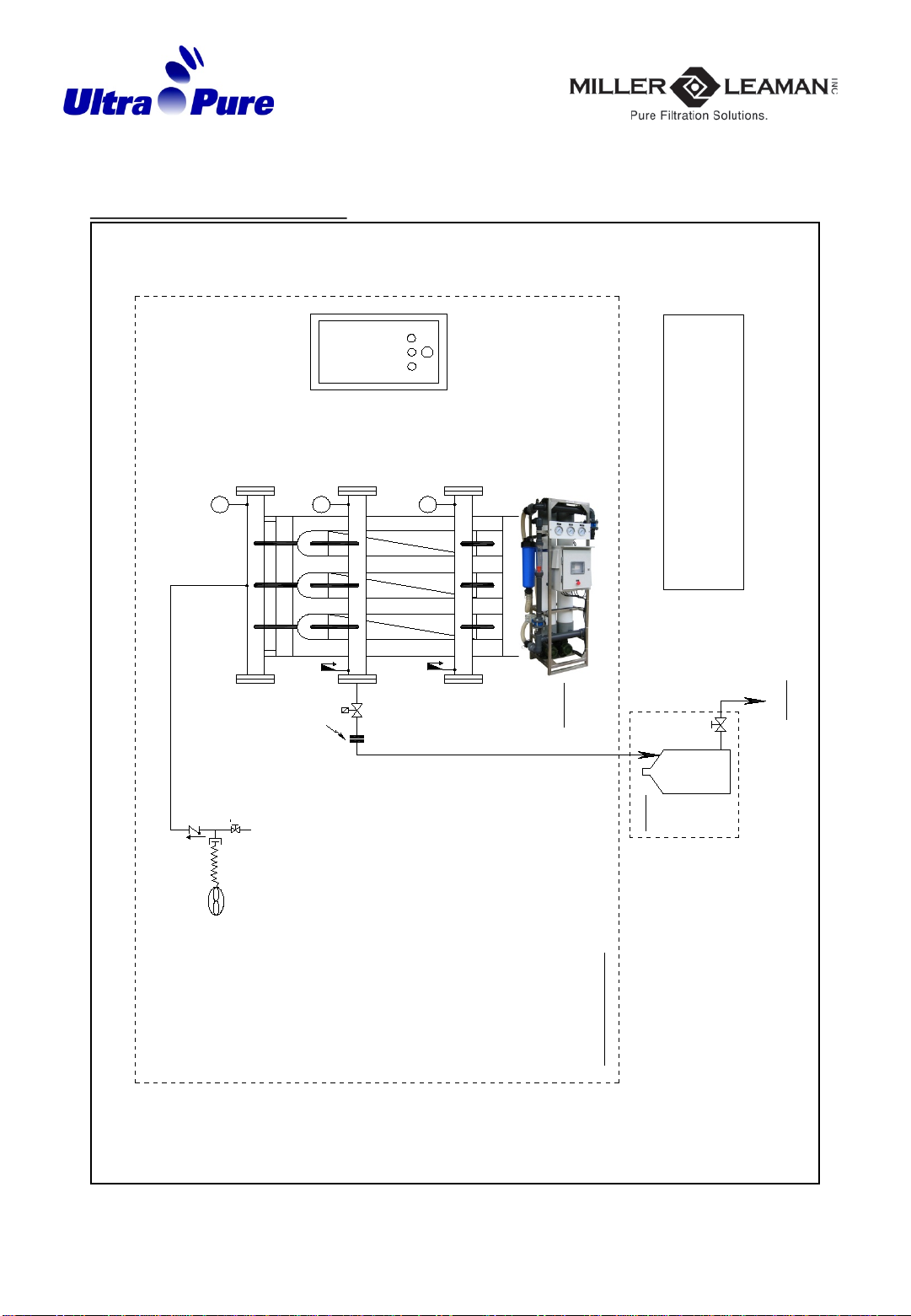
2. Process and Plant setup Diagram
P1
P3
P2
Product Out
(>95% Volume)
Product/Backflush Tank
Tank Volume : Depends on usage pattern.
FEED
Feed
Flow
P0
Guard Filter
CV-1
Product
Flowmeter
Connecting
Point
Control
Panel
(Electrical)
Product Flow PRODUCT
Ultra-Flo Membrane Module
Membrane Skid
SCOPE OF SUPPLY
Guard-Filter Bag size selection :
Filtration : 100 um size.
CIP : 50 um size
H
L
Pressure
Relief Valve
REJECT
to drain
(<5% Volume)
(Keep this pipeline big & short)
EBF
Tank
Drain
Connecting
Flange
Backflush Pump
Check
Valve Backflush
Flow
BACKFLUSH
(Keep this pipeline big & short)
Backflush Tank
Valve
EBF Feed
Valve
Tank Volume:
150L/membrane
CV-2
Feed Tank
Valve
Feed Tank
Tank Volume : 20 ~ 30 mins holding time.
Check Valve
Connecting
Flange
Connecting
Flange
L
Feed Pump
Dosing
Tank
Dosing
Pump
CIPV-1
MV-1
Optional
Air Blower
Check
Valve
1
4
" Drain
Valve
Hose
Pressure
Relief Valve
CIP Feed
Valve
DRAIN
Reject/CIP
Tank
Optional
Optional
MV-2
CIPV-2
Drain
Valve

E-mail : sales@millerleaman.com
www.millerleaman.com
5
3. Process Description: (2-Valve Control)
Start process in ‘Auto’. Select SS-1 to “Auto”, depress PB-1 “System On/Off” once to
start. The system will go through the following sequence.
P1 – Feed Pressure
P2 – Air Scouring Pressure
P3 – Backflush Pressure
1. Filtration cycle ( T1 ) (Refer to Filtration Flow Diagram Page 8)
Aim : Produce Filtered Water
CV-1 Close, CV-2 Open, Feed Pump On, Backflush pump Off, Blower Off
Outside to inside flow, on a dead-end configuration.
Filtration cycle will pump feed water through the Guard-strainer to the membrane
cartridges. Filtered product water will flow through the flow-meter to the Product /
Backflush Tank.
Filtration Pressure (P1 – P3 = TMP1), maximum at 8 psi (Default setting at 3 psi)
Filtration Pressure / product flow rate can be increase or decrease by adjusting from the
frequency controller (refer to inverter operating manual).
(Start filtration at low pressure first, example at 1 psi for a few cycles and records
down the parameters before increasing to higher pressure/flow.)
Time duration is set in the PLC, ‘Filtration’(T1). (Default is at 5 minutes)
Timer duration can be set longer according to the feed water condition.
2. Air Scouring cycle ( T2 ) (Refer toAir Scouring Diagram Page 9)
Aim : Dislodge Suspended Solids from Membrane
CV-1 Open, CV-2 Close, Feed Pump Off, Backflush pump Off, Blower On
Air scouring is a process of releasing air bubbles into the membrane cartridge via the
Blower.
When the Blower is activated, air scouring pressure gauge (P2) should read 1.5 ~ 2.0 psi
above the gauge reading.
This will dislodge suspended solids from the membrane surface. Time duration is set in
the PLC, ‘Air-Scouring’ (T2). (Default is at 30 seconds)
Timer duration is set according to the feed water condition.

E-mail : sales@millerleaman.com
www.millerleaman.com
6
3. Air Scouring + Backflush cycle ( T3 ) (Refer toAir Scouring + Backflush Flow Diagram
Page 10)
Aim : Membrane Regeneration
CV-1 Open, CV-2 Close, Feed Pump Off, Backflush pump On, Blower On
Inside to outside flow, on a dead-end configuration.
Backflush cycle will pump product water through the membrane cartridges through Reject valve CV-1
for disposal.
Backflush Pressure (P3 – P1 = TMP2) maximum of 14 psi (When Blower is Activated)
Backflush pressure or flow rate can be either increase or decrease by adjusting from the frequency
controller (refer to the inverter operating manual).
Time duration is set in the PLC, ‘Backflush’(T3). (Default is at 30 seconds)
Timer duration is set according to the feed water condition.
Backflushing flow rate during this cycle is much higher relative to the filtration cycle, 6-7m3/h per
membrane. Important to keep the following pipelines big in diameter and short in length:
- suction pipe line from tank to backflush pump.
- reject pipe line after CV-1, to open drain.
Important Instructions:
Flushing Instructions:
Membrane contains preservatives such as sodium meta-bisulphite or glycerine. Flush the membrane
with clean water (normally city water) for about 10mins before operating the system.
Bag Filter:
It is a routine operational procedure to monitor and to ensure that the bag filter is not clogged. If the
flowrate decreases or if the differential pressure between the bag filter and feed pressure (P0-P1)
exceeds 10psi, changing or cleaning the filter bag must be done immediately.
System startup procedure:
Start operating this system with clean water (normal city water supply) in the feed tank. Operate the
system for 30 minutes with this feed water. Record the operating parameters and keep this as the
reference for this plant.
Long term usage:
During long term usage, it will be useful to add a shock level of biocide into the feed water on a once a
day basis. Chlorine can be applied at a dosage below 20 ppm. Other forms of non-oxidizing biocide
can be applied at higher levels.
Testing of Free Chlorine:
Free Chlorine concentration in the water can easily be measured by using a simple comparison of a
colour scale with a test strip. Recommended chlorine test strips - Chlorine Test
Cat No. Measuring Range – mg/l/Cl2
1.17924.0001 25 ~ 500
1.17925.0001 0.5 ~ 20

E-mail : sales@millerleaman.com
www.millerleaman.com
7
Filtration Flow Diagram
P1
P3
P2
Product Out
(>95% Volume)
Product/Backflush Tank
Tank Volume : Depends on usage pattern.
FEED
Feed
Flow
P0
Guard Filter
CV-1
Product
Flowmeter
Connecting
Point
Control
Panel
(Electrical)
Product Flow
PRODUCT
Ultra-Flo Membrane Module
Membrane Skid
SCOPE OF SUPPLY
Guard-Filter Bag size selection :
Filtration : 100 um size.
CIP : 50 um size
H
L
Pressure
Relief Valve
CV-2
Feed Tank
Valve
Feed Tank
Tank Volume : 20 ~ 30 mins holding time.
Check Valve
Connecting
Flange
Connecting
Flange
L
Feed Pump
MV-1
Pressure
Relief Valve
MV-2
E-mail : sales@millerleaman.com
www.millerleaman.com
8
Air Scouring Diagram
P1
P3
P2
CV-1
Control
Panel
(Electrical)
Ultra-Flo Membrane Module
Membrane Skid
SCOPE OF SUPPLY
Guard-Filter Bag size selection :
Filtration : 100 um size.
CIP : 50 um size
Pressure
Relief Valve
REJECT
to drain
(<5% Volume)
(Keep this pipeline big & short)
Connecting
Flange
Air Blower
Check
Valve
1
4
" Drain
Valve
Hose
Pressure
Relief Valve
DRAIN
Reject/CIP
Tank
Optional
Drain
Valve

E-mail : sales@millerleaman.com
www.millerleaman.com
9
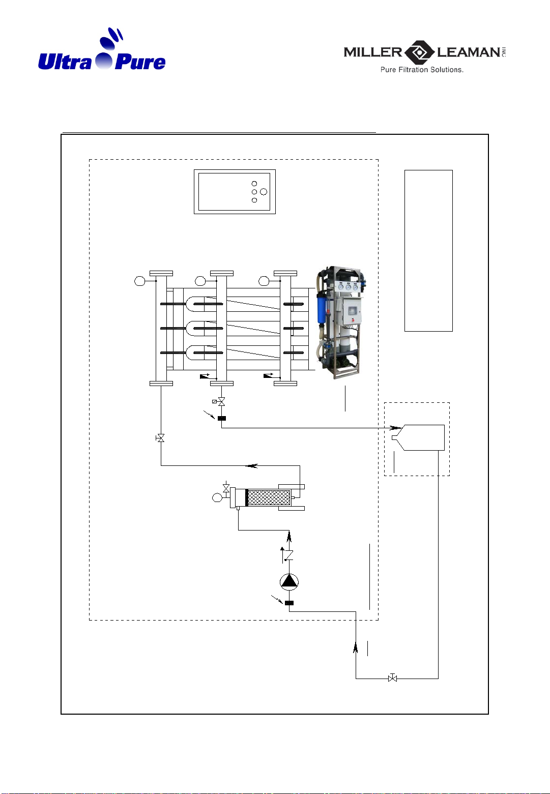
Air Scouring + Backflush Flow Diagram
P1
P3
P2
Product/Backflush Tank
Tank Volume : Depends on usage pattern. CV-1
Control
Panel
(Electrical)
Ultra-Flo Membrane Module
Membrane Skid
SCOPE OF SUPPLY
Guard-Filter Bag size selection :
Filtration : 100 um size.
CIP : 50 um size
H
L
Pressure
Relief Valve
REJECT
to drain
(<5% Volume)
(Keep this pipeline big & short)
Connecting
Flange
Backflush Pump
Check
Valve Backflush
Flow
BACKFLUSH
(Keep this pipeline big & short)
Backflush Tank
Valve
Connecting
Flange
Dosing
Tank
Dosing
Pump
Optional
Air Blower
Check
Valve
1
4
" Drain
Valve
Hose
Pressure
Relief Valve
DRAIN
Reject/CIP
Tank
Optional
Drain
Valve

E-mail : sales@millerleaman.com
www.millerleaman.com
10
4. Membrane Regeneration
After some time of usage, and depending on the feed water conditions, the membrane
cartridges may experience fouling. This will result in a drop in product flow rate and/or
an increase in filtration pressure. Aregeneration procedure can be performed to
reverse this situation.
4.1 *Optional : Functional EBF (T4)
(Default frequency of Fuctional EBF is set at every 24hrs)
(Refer to Page 10)
Aim : Membrane Regeneration
(Enhance Backflushing at Periodic Time to Prevent Further Fouling)
A shock level of free chlorine at 20ppm is added into the backflushing stream during the
backflushing cycle. This is done automatically by having an optional dosing system
(Pump and Chemical Tank) to pump in the required amount of chlorine.
According to the feed water condition, the frequecy of dosing can be determined in PLC
‘FEBF’ (Timer T4). The default frequency is once every 24hrs. To activate or deactivate
the dosing simply by connecting or disconnecting the power plug provided.

E-mail : sales@millerleaman.com
www.millerleaman.com
11
4. Membrane Regeneration
4.2 Enhanced Backflush “EBF” (Refer to EBF Flow Diagram Page 13)
EBF is a process of backflushing the membrane cartridges
with a preferred chemical for cleaning purpose. This regeneration process will
reverse the fouling issue. It should be implemented as a routine during the usage
of this system. Depending on the feed water conditions and system performance,
it can be performed on a daily, every 2 or 3 days, or even weekly basis.
Before starting the EBF. Step 1 and 2 will put the system through a normal Air
Scouring + Backflush cycle to reduce some loading before chemical usage.
1 Air Scouring + Backflush the system once, depress PB-2 ‘Backflush’ button.
2 Stop the system, depress PB-1 ‘System on/off’ button.
3 Fill-up the ‘Backflush Tank’ with reference amount of clean water (prefer
from its own product water or directly from the utility water).
Add chemical to EBF tank (selection depends on fouling conditions)
Select to Backflush from EBF tank by setting manual valve.
• 20-100 ppm of chlorine, Cl2( Organics and Biological ), Or
•pH 2 for acid cleaning ( Inorganic and scaling ), Or
•pH 11 for alkaline cleaning (Organics and Biological )
4To commence EBF. Select SS-1 to “EBF” depress PB-1 “System On/Off” once
to start the EBF process. The system will go through one cycle of Air
Scouring + Backflush. Depress PB-1 “System On/Off” again to stop the
system.
5Soak the membrane cartridges for about 10-20 mins.
6 Repeat Step 4 & 5 if necessary.
7 Select Backflush from Product / backflush tank, by setting manual valve.
8Select SS-1 to ‘Auto” start filtration by depress PB-1 “System On/Off” once.
Air Scouring + Backflush the system once, depress PB-2 ‘Backflush’ button.
This will help to neutralize the residual chemical in the system
9 End of EBF

E-mail : sales@millerleaman.com
www.millerleaman.com
12
4.2 Membrane Regeneration (EBF) Flow Diagram
P1
P3
P2
CV-1
Control
Panel
(Electrical)
Ultra-Flo Membrane Module
Membrane Skid
SCOPE OF SUPPLY
Guard-Filter Bag size selection :
Filtration : 100 um size.
CIP : 50 um size
Pressure
Relief Valve
REJECT
to drain
(<5% Volume)
(Keep this pipeline big & short)
EBF
Tank
Drain
Connecting
Flange
Backflush Pump
Check
Valve Backflush
Flow
BACKFLUSH
EBF Feed
Valve
Tank Volume:
150L/membrane
Connecting
Flange
Air Blower
Check
Valve
1
4
" Drain
Valve
Hose
Pressure
Relief Valve
DRAIN
Reject/CIP
Tank
Optional
Optional

E-mail : sales@millerleaman.com
www.millerleaman.com
13
4.3 Clean In Place “CIP” (Refer to page 15 & 16)
CIP is a process of cross flowing the membrane cartridges with the preferred Chemicals for
cleaning purpose. This regeneration process will reverse the fouling issue.
It should be implemented as a routine during the usage of this system. Depending on the feed
water conditions and system performance, it should be performed on a routine basis.
Before starting the CIP; Step 1 will put the system through a normal Air Scouring + Backflush
cycle to reduce some dirt loading before chemical usage.
1 Air Scouring + Backflush the system once, depress PB-2 ‘Backflush’ button.
2 Stop the system, depress PB-1 ‘System on/off’ button.
3Close the drain valve to convert the Reject tank as CIP tank.
4 Fill-up the CIP Tank with reference amount of clean water (prefer its own product
water or directly from utility water supply). Add chemical to CIP tank (selection depends
on fouling conditions)
•50-100 ppm of chlorine, Cl2( Organics and Biological ),Or
•pH 2 for acid cleaning ( Inorganic and scaling ), Or
•pH 11 for alkaline cleaning (Organics and Biological )
5 Close manual valve from feed tank (MV-2) and open manual valve to CIP tank (CIPV-2).
Open manual valve to air manifold (CIPV-1), close manual valve to feed manifold (MV-1).
Change filter bag to 50/100µm.
6 To commence CIP. Select SS-1 to “CIP”, then depress PB-1 “System On/Off” once to start
the CIP process. Adjust the feed pump frequency to 45Hz in order to achieve a good circulation
flowrate.
7 In CIP mode, the system will go through an alternate process of cross flow and air
scouring for 5mins (TT6A) and 20secs (TT6B) respectively. There will be 5 cycles, at the
end of 5th cycle, the cartridges will be soaked for 10mins. At the end of 10mins of
soaking, the above 5 cycles will be repeated. After which the system will automatically
off. End of CIP.
8 Reverse the actions in above step 3 to 5.
9 Reset the feed pump frequency back to normal. Start filtration. Select SS-1 to “Auto”,
depress PB-1 “System On/Off” once. Air Scouring + Backflush the system once, depress PB-2
‘Backflush’ button. This will help to neutralize the residual chemical in the system.
10 Process in ‘Auto’.
E-mail : sales@millerleaman.com
www.millerleaman.com
14
4.3 Membrane Regeneration (CIP) Flow Diagram
P1
P3
P2
FEED
Feed
Flow
P0
Guard Filter
CV-1
Control
Panel
(Electrical)
Ultra-Flo Membrane Module
Membrane Skid
SCOPE OF SUPPLY
Guard-Filter Bag size selection :
Filtration : 100 um size.
CIP : 50 um size
Pressure
Relief Valve
REJECT
to drain
(<5% Volume)
(Keep this pipeline big & short)
Check Valve
Connecting
Flange
Connecting
Flange
Feed Pump
CIPV-1
Pressure
Relief Valve
CIP Feed
Valve
CIP
Tank
Optional
CIPV-2

E-mail : sales@millerleaman.com
www.millerleaman.com
15
Reject/CIPTank Connection Drawing
6" PVC SCH 80
Pipe
3" PVC SCH 80
Pipe
3" PVC Manual
Valve
Feed Tank
4"
Backflush Tank
Drain Valve
Drain
Valve to feed manifold (MV-1) Valve to air manifold (CIPV-1)
MV-2
CIPV-2

E-mail : sales@millerleaman.com
www.millerleaman.com
16
5. System / Electrical Control & Schematics

E-mail : sales@millerleaman.com
www.millerleaman.com
17
Basic controls on Starting and Stopping the System
Level switches controls on the System
Contact close (level above switch): System run
Contact open (level below switch): System will
skip ONE backflush cycle, system will stop on
SECOND backflush cycle
Product / Backflush Tank Low Level
Switch
(TB-24, 25)
3
Contact close (level above switch): System run
Contact open (level below switch): System stop
Product / Blackflush Tank High
Level Switch
(TB-22, 23)
2
Contact close (level above switch): System run
Contact open (level below switch): System stop
Feed Tank Low Level Switch
(TB-20, 21)
1
1 Release “Emergency Stop” Switch (PB-0)
(turn red knob clockwise) Connect power supply to PLC,
Control Valves, Flow-switches, etc.
2 Select Selector switch SS1 to ‘AUTO’
3 Press “System On/Off” button ONCE (PB-1) Step 1 : Filtration
(Start process) Step 2 : Air Scouring only
Step 3 : Air Scouring & Backflush
Return to Step 1
4 Press “Backflush” button ONCE (PB-2) Jump to
(enabled only during Filtration cycle) Step 2 : Air Scouring only
Step 3 : Air Scouring & Backflush
Return to Step 1
5 Press “System On/Off" button ONCE (PB-1) System Stop
(Stop process) (Filtration time stopped at last
count)

E-mail : sales@millerleaman.com
www.millerleaman.com
18
PLC settings, changing timer on Filtration, Air scouring, Air scouring + Backflush, FEBF,
Air Scouring frequency during CIP & Air Scouring duration during CIP.
Warning : Do not change other parameters or settings, except TT1, TT2 ,TT3, TT4, TT6A &
TT6B
Press ▲to increase or ▼to decrease timing
6
Press MENU/OK and then select Yes to save new
setting
7
Press MENU/OK to return to Run screen8
Time setting will “blink”
Press MENU/OK once then ►to change set time
5
Press ▲/ ▼to TT1(Filtration), TT2 (Air scouring), TT3
(Air Scouring + Backflush), TT4 (FEBF Frequency),
TT6A (Air Scouring frequency during CIP), TT6B (Air
Scouring duration during CIP)
4
Press MENU/OK once to enter parameter setting3
Press ▲/ ▼to select ‘PARAMETER’
2 Press MENU/OK once to enter Mode page1
Inverter settings, changing Filtration & Backflushing pump frequency setting
Warning : Do not change other parameters or settings, except for 3-10-0 & 3-10-1
3-10-0 – FEED PUMP FREQUENCY 25 Hz (25%)
3-10-1 – B/F PUMP FREQUENCY 35 Hz (35%)
1.To enter the Main Menu,press [MENU] key unti
indicator in display is placed above
Main Menu.
1.Use ▲/ ▼to browse through the parameter
groups 3-10-0 & 3-10-1.
1.Press [OK] to select a parameter group.
2.Use ▲/ ▼to browse through the parameters in the
specific group.
3.Press [OK] to select the parameter.
4.Use ▲/ ▼to set/change the parameter value.
5.Press [OK] to accept the value.
6.To exit, press either [BACK] twice to enter Quick Menu,
or press [MENU] once to enter Status.

E-mail : sales@millerleaman.com
www.millerleaman.com
19
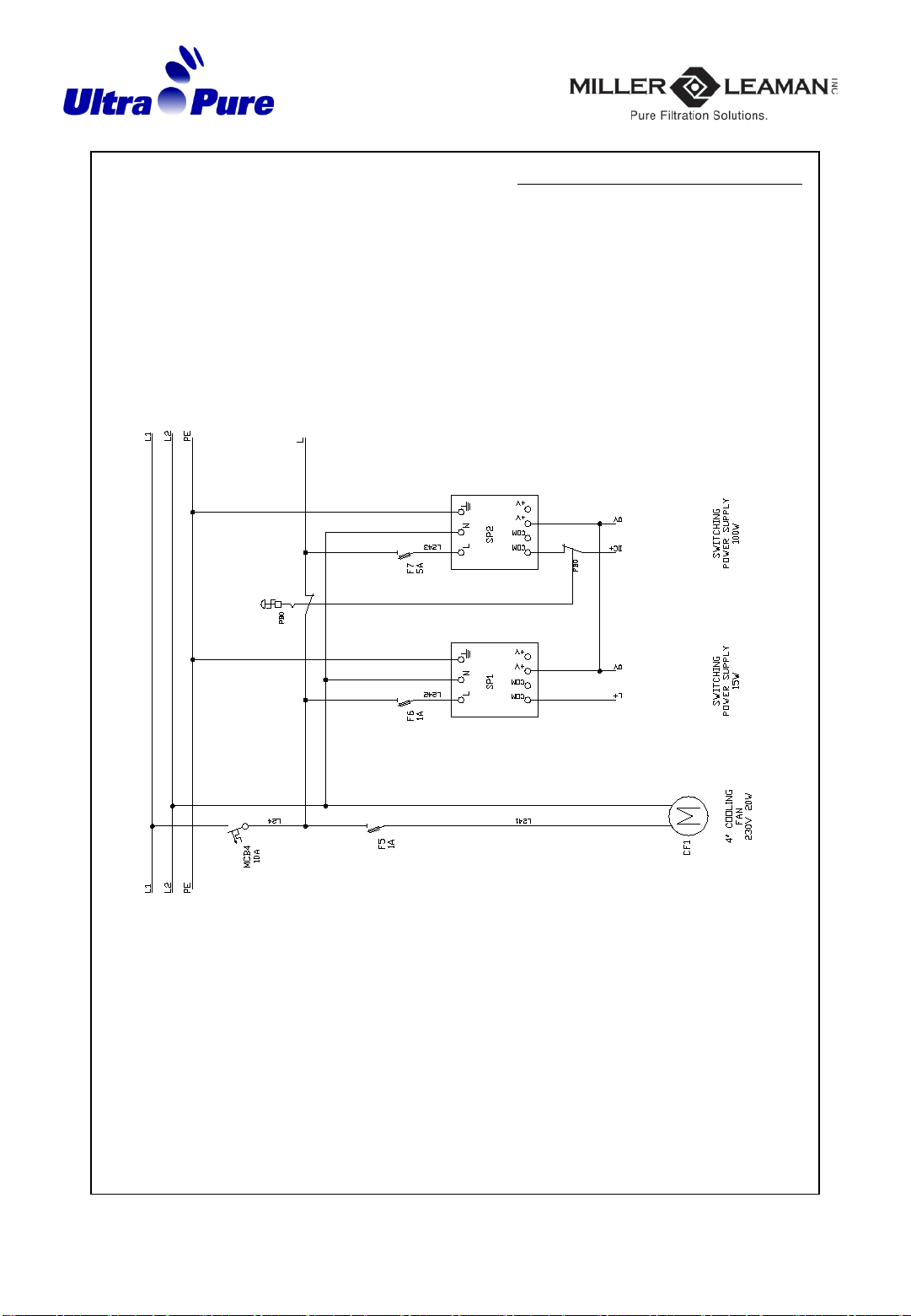
ML-02 - 4 Electrical Drawing (a)
E-mail : sales@millerleaman.com
www.millerleaman.com
20
ML-02 - 4 Electrical Drawing (b)
This manual suits for next models
1
Table of contents
Other Miller-Leaman Water Filtration System manuals


Popular Water Filtration System manuals by other brands

 RO Dia II HT operating instructions")


Graf
Graf Optimax-XXL DN300 Installation and maintenance instructions

Schaffner
Schaffner FN5420 User and installation manual

Grunbeck
Grunbeck pureliQ:K Operation manual

KOGANEI CORPORATION
KOGANEI CORPORATION FRZ Series instruction manual

Vizion
Vizion UF-216 series owner's manual

Philips
Philips AUT7006 user manual


