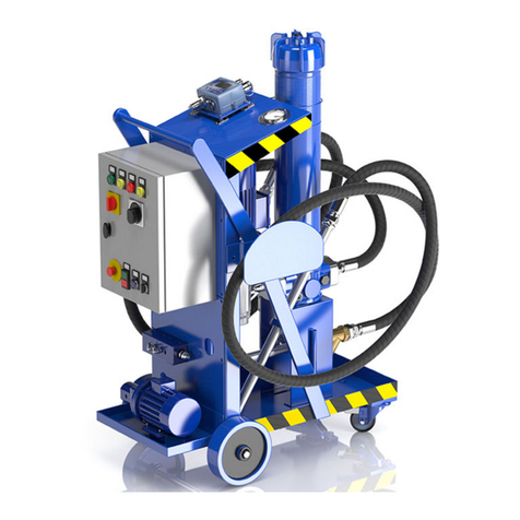
MPFiltri UFM181 User manual

TO PERFORMPASSION
User’s Manual UFM181
Mobile ltration unit


PRODUCT OVERVIEW
UFM181 ltration unit series
Key features:
- Transfer
- Filtration
- Flow rates 180 l/min
- Maximum working pressure 10 bar
- Absolute ltration
- Wide range of ltration media
- Water removal lter elements
- Single-phase and three-phase motors
- Comprehensive choice of congurations
- In-line contamination monitoring (ICM2.0 series particle counter)
- Equipped with handles and wheels for easy portability
- standard
Mobile ltration unit
1

Mobile ltration unit
2

DECLARATION OF CONFORMITY
The company:
MP Filtri S.p.A.
Via 1° Maggio, 3
20042 - Pessano con Bornago (MI) - Italy
as a manufacturer, it declares that the machine:
DECLARATION OF CONFORMITY IN ACCORDANCE WITH 2006/42/EC MACHINERY DIRECTIVE
EC declaration
to which this declaration refers, complies with the following Directives: 2006/42/EC Machinery Directive.
Furthermore, the technical documentation was compiled in accordance with Annex VII Part A.
The machine also complies with the provisions of the following standards:
UNI EN ISO 12100-1-2:2010
Safety of machinery
UNI EN ISO 13857:2008
Safety of machinery - Safety distances to prevent the reaching into dangerous areas with the upper and lower limbs
UNI EN ISO 13732-1:2009 Ergonomics of thermal environments - Methods for evaluating human response to contact with surfaces
UNI EN ISO 4413:2012 Hydraulics - General rules and safety requirements for systems and their components
Pessano con Bornago, 14/05/2019
Chief Executive Ofcer
CEO
Code / Model
UFM181TA3020P01
UFM181TA3021P01
Name
MOBILE FILTRATION UNIT
Mobile ltration unit
3

PRODUCT OVERVIEW
Declaration of Conformity
Table of contents
GENERAL WARNINGS
1 General warnings and information for the recipient
1.1 General information
1.2 General and safety instructions
1.3 Operator station and dangerous areas
1.4 Hazards and risks that cannot be eliminated
1.5 Personal protective equipment
TRANSPORT AND STORAGE
2 Transport and handling conditions
GENERAL WARRANTY CONDITIONS
3 Warranty, limits and exclusions
PRODUCT DOCUMENTATION
4 Mobile transfer and ltration units
4.1 Test certicate
4.2 Download Area
1
3
4
6
6
6
8
8
8
9
11
12
13
13
Page
Mobile ltration unit
4

TABLE OF CONTENTS
Page
5 Technical features
5.1 Dimensions
5.2 Hydraulics diagrams and material list
6 Installation procedures and general operation
6.1 Introduction
6.2 Filter element installation
6.3 Wiring diagram
6.3.1 Electrical connection
6.3.2 Triangular electrical connection of a three-phase motor
6.3.3 Electrical connection of a single-phase motor
6.3.4 Electrical panel
6.3.5 Electrical panel labels
6.4 Use
6.4.1 Installation
6.4.2 Power on
6.4.3 Air vent
6.4.4 Oil analysis with particle counter
6.4.5 Shutdown
6.4.6 Operating limits and environmental limits
6.5 Normal and scheduled maintenance
6.5.1 Oil leaks
6.6 Filter clogging
6.6.1 Replacing lter element
6.6.2 Air vent
6.6.3 Replacing and cleaning of the lter in the suction line
7 Designation & ordering code
8 Spare parts
8.1 List of spare parts
8.2 Filter element detail
UFM 181 - MOBILE FILTRATION UNIT
15
16
17
19
19
19
20
20
20
-
21
21
22
22
23
24
24
25
25
26
26
26
27
28
28
29
30
30
32
Mobile ltration unit
5

1 General warnings and information for the recipient
1.1 General information
The mobile ltration units of the UFM series have been designed and manufactured in compliance with the machinery directive and
the low voltage directive with regards to electric motors. The EC Declaration of Conformity is included in this manual.
The warranty has a duration of twelve months starting from the date shown on the delivery note. To consulte “General Warranty
Conditions” section of this Use and Maintenance Manual.
1.2 General and safety instructions
Read this manual carefully before commissioning, maintenance or other activities on or with the unit. Each operator involved in the
operation of the mobile ltration unit must wear the following personal protective equipment:
Before carrying out any installation or work on and/or with the machine it is necessary to strictly follow the instructions listed in
this manual. It is also necessary to comply with the provisions in force concerning accident prevention and safety in the workplace.
The warnings to prevent dangers to the health of the personnel assigned to the machine, are highlighted in this documentation
with signal words to notications:
Safety glasses Safety shoes Gloves
This means that failure to comply with the relevant safety regulations may result in slight injury
or damage to equipment.
If important information concerning the product affects the use of the product or a part of this
documentation, all of it must be particularly taken into account.
This means that failure to comply with the relevant safety regulations can result in death, serious injury
or considerable damage to equipment.
CAUTION
NOTE
DANGER
!
!
!
Mobile ltration unit
6

GENERAL WARNINGS
To allow rapid identication of the employees who must read this manual, denitions have been used with the following meaning:
The person in charge of using the machine for productive purposes. The operator is aware of the
measures taken by the machine manufacturer to eliminate the sources of risk of accidents at
work and complies with the operational constraints.
The person in charge of performing maintenance operations on the machine. The maintenance
technician is aware of the possible dangerous situations that may arise during his work and
takes the necessary precautions to avoid risks of accidents at work.
The person in charge of carrying out maintenance operations on the machine's electrical system.
The electrician is aware of the possible dangerous situations that may arise during his work and
takes appropriate precautions to avoid risks of accidents at work.
The person in charge of handling the machine or parts thereof. The slinger is aware of the
problems concerning the transport of machines or parts thereof in safe conditions; for this
purpose, they use lifting equipment suitable for the purpose following the instructions provided
by the machine manufacturer.
The person in charge of preparing the machine for normal operation. The machine setter is
aware of the measures taken by the machine manufacturer to eliminate the sources of risk of
accidents at work and complies with the operational constraints. The machine setter takes the
necessary precautions to intervene in conditions of maximum safety.
OPERATOR
MAINTENANCE
TECHNICIAN
ELECTRICIAN
PERSONNEL INVOLVED
IN SLINGING AND
HOISTING OPERATIONS
MACHINE SETTER
Mobile ltration unit
7

1.3 Operator station and dangerous areas
Areas adjacent to the electric motor due to the presence of live equipment and potentially very hot surfaces are to be considered
as dangerous areas. The operator has no reason to access electrical equipment and is not authorised to do so.
1.4 Hazards and risks that cannot be eliminated
Risk of electric shock on the electric motor, in case of motor malfunction, risk of burns due to high temperature, accidental oil
leakage with consequent possibility of slipping, rupture of the hoses with consequent loss of lubricant.
With oil temperatures above 40/45 °C, take extra caution in the handing of metal lances/tubes and movement of the mobile
ltration unit. Avoid direct contact with hot oil and the lter housing.
1.5 Personal Protective Equipment
For normal use of the mobile ltration unit, safety shoes, gloves and safety glasses must be worn. In general the PPE to be used
according to the operations on the machine are summarised in the following table:
OPERATION
Normal operation
Normal maintenance
Safety shoes, protective
gloves, safety glasses
Safety shoes, protective
gloves, safety glasses
PPE
The trolley must be taken out of service and/or dismantled in full compliance with the regulations in force
at that time in the country where the machine is installed.
The machine is not suitable for outdoor use and all electrical equipment
has a minimum degree of protection IP 55.
NOTE
NOTE
!
!
Mobile ltration unit
8

TRANSPORT / STORAGE
2 Transport and handling conditions
The ltration unit is transported packaged with strapping and plastic lm.
The product is moved by means of wheels. The movement of the same is carried out by acting on the special handle.
The weight of each individual unit is shown below:
Total weight UFM181 109 kg
Mobile ltration unit
9

Mobile ltration unit
10

GENERAL WARRANTY CONDITIONS
3 Warranty, limits and exclusions
1 - The seller assumes a guarantee of the normal mechanical operation of their product for a period of one year (except as provided
for in Item H4 referred to the general conditions of sale and warranty sent with each order conrmation) from the delivery date.
2 - The warranty is limited to the replacement of damaged or defective parts due to poor quality of the material or construction. It
does not extend to defects due to normal wear or due to inexperience or negligence of the customer and to parts that due to
the composition of the material or the nature of their use are subject to rapid wear.
3 - Damage or defects must be declared, under penalty of forfeiture, by registered letter within eight days of discovery.
The seller, once being aware of the existence of the defect, is obligated to replace the defective elements if they have not been
tampered with due to attempted repair or modication by the customer (or third parties), and provided that he has punctually
fullled the contractual obligations, with particular regard to payments which, if not carried out in the manner and within the
agreed terms, entail the forfeiture of the guarantee and the seller's right not to effect the replacements.
4 - Any other indemnity, request for compensation for damages, also by third parties, due to production shutdown of the customer
is expressly excluded.
5 - The items to be replaced must be sent with transport costs to be paid by the purchaser ex works of the seller who will replace
them as soon as possible with delivery to their premises. The replaced parts belonging to the customer remain at his disposal
for eight days within which they can be collected; following this deadline the seller is entitled to regard them as scrap in his
possession without any compensation.
6 - The examination of the failures and their causes will always be carried out in the seller’s workshops and all the related costs
will be borne by the customer. The customer is also responsible for all inspection costs that may be requested on site. In no
case may the customer demand the termination of the contract.
7 - The warranty is not transferable and applies only to the invoice recipient.
8 - The warranty is no longer valid when one of the following conditions is the case:
a) payments are not made by the client in the manner and terms agreed
b) tampering with what is provided without the seller's explicit authorisation
c) improper use of what is supplied
d) failure to perform maintenance
e) installation, modication, replacement of parts or of what is supplied
Mobile ltration unit
11

For other types of uids contact our technical / commercial service. NOTE
4 Mobile transfer and ltration units
The UFM series mobile ltration units are machines designed for transferring and ltering lubricants and hydraulic oils.
The UFM015 version can be moved thanks to the use of handle and low weight, all other versions have wheels for moving.
They can be used with uids at different temperatures (therefore different viscosities) as long as they fall within the limits indicated
by this manual. Operation with Mineral Oils, Synthetic Fluids & HFCs.
The machine can be used for:
TRANSFER
- transferring from drums into tanks
- to rell from drums into tanks
FILTRATION
- off-line ltration in tanks
- additional off-line ltration system in tanks
- off-line ltration of new oil into drums or underground/large tanks
- Particle counting and determination of cleanliness class according to ISO4406, NAS1638, AS4059
(only for versions with ICM mounted on UFM051-091-181-919)
- Measurement of the water saturation level (RH) contained in the uid and of the temperature
Depending on the version, the mobile ltration units can use lter elements and cartridges with different ltering media, ltration
degree and dimensions; the bre lter elements have high storage capacity and absolute ltration ßx(c)>1000.
Single-phase and three-phase electric motors.
Wide range of ow rate, from 15 l/min to 180 l/min.
Optical and electrical systems for lter monitoring.
Electrical systems for greater safety:
- unit shutdown in case of clogged lter (from the UFM041 version onwards)
- unit shutdown when the set cleanliness class is reached (particle counter version only).
Before commissioning the equipment make sure:
- you have read this manual carefully
- check the good condition of the mobile ltration unit
- report any damage or breakages suffered by the mobile ltration unit during transport
- verify the presence of all the accessories supplied
NOTE
Mobile ltration unit
12

PRODUCT DOCUMENTATION
UFM 091
UFM 015
USER’S MANUAL - UFM series
UFM 041
UFM 181
UFM 051
UFM 919
CONTAMINATION MONITORING
PRODUCTS General catalogue
Download
PDF
QUICK GUIDE
UFM series
Download
multi-language
PDF
MOBILE FILTRATION UNIT
General catalogue
Download
PDF
Select your language
and download PDF
EN
CMP View Software
Software multilingual
CMP View Software
Quick Guide
Select your
language and
download PDF
Download
Software
Select your
language and
download PDF
ICM
User’s Guide
4.1 Test certicate
Hard copy of test certicate is attached to the cart.
4.2 Download Area
Please scan the QR codes below to get updated electronic version of the related document.
Mobile ltration unit
13

Mobile ltration unit
14

UFM181
The system is supplied without lter element NOTE 2
5 Technical features
The mobile ltration unit consists of a support frame with handle and wheels for manoeuvrability.
The assembly/motor pump connected to the hoses is used for suctioning and discharging
the uid.
It is equipped with a suction lter and a discharge lter.
The mobile ltration unit is complete with electrical and mechanical safety systems, for
the lter and the assembly/motor pump.
Pump
Electric motor
Flow rate (l/min)
Max. working pressure
Viscosity
Suction lter
Type of ltering mat/degree of ltration
Internal/external ltration
Bypass valve ∆p set
Fluid temperature
Ambient temperature
Protection class
Seals
Compatibility with hydraulic uids
Hoses
Weight
Standard equipment
Equipment according to the versions
UFM181TA3020P01
UFM181TA3021P01
Screw pump with integrated pressure relief valve
4 kW 400/230 V three-phase - 2 poles
180 l/min - 2900 rpm
10 bar
Minimum operating viscosity 10 cSt
Maximum operating viscosity 800 cSt
Maximum only for cold starts 2000 cSt
Y-shape ne lter unit 800 µm
Fibre 1/3/6/10/16/25 βx(c)>1000
Wire mesh 25/60 µm
Water absorber
3.5 bar
from -10 °C to +80 °C
from -20 °C to +45 °C
IP 55
NBR
Mineral & Synthetic oils. For other uids contact MP Filtri.
Flexible suction hose DN50 L = 3000mm
Nozzle Øe = 50 L = 700mm
Flexible delivery hose DN38 L = 3000mm
Nozzle Øe = 42 L = 700mm
109 kg
Main lter bypass valve blocking
Pressure gauge
Electric clogging indicator with automatic motor stop
Electric clogging indicator with automatic motor stop,
ICM2.0 series particle counter and communication module
NOTE 1 NOTE 2
Microbre lter elements with water absorber: disposable components NOTE 1
Mobile ltration unit
15

5.1 Dimensions
Drain valve
Mobile ltration unit
16

UFM181TA3020P01
Version:
UFM181
Position Quantity Description
800 µm Y shaped lter
Gear pump / screw
Motor/pump coupling
Three-phase electric motor 4 kW 2P-B3/B5 (IE3)
Increased lter length
Microbre lter element 1 µm
Microbre lter element 3 µm
Microbre lter element 6 µm
Microbre lter element 10 µm
Microbre lter element 16 µm
Microbre lter element 25 µm
Filter element in wire mesh 25 µm
Filter element in wire mesh 60 µm
Water absorber lter element
Electric diff. pressure indicator (visual indication on panel)
Pressure gauge
Mobile unit frame
DN50 exible suction hose + nozzle
DN38 exible discharge hose + nozzle
Electrical panel three-phase version
Drain valve
Air vent valve
1
1
1
1
1
1
1
1
1
1
1
1
1
1
1
2
3
4
5
5.1
6
7
8
9
10
11
12
13
Microbre lter elements with water absorber: disposable components NOTE
NOTE
5.2 Hydraulic circuit and bill of materials
>> NEXT
PRESSURE
(OUT)
SUCTION
(IN)
180 l/min
G 1”
G 1 - 1/4”
Mobile ltration unit
17

A = IN Auxiliary pump for ICM2.0
B = IN ICM 2.0
C = OUT ICM 2.0 (closed)
D = OUT ICM 2.0
E = RETURN
F = RETURN (closed)
MP1 = Minimess - IN ICM 2.0
MP2 = Minimess - OUT ICM 2.0
UFM181TA3021P01
Version:
Position Quantity Description
Y shaped lter 900 µm
Gear pump / screw
Motor/pump coupling
Three-phase electric motor 4 kW 2P-B3/B5 (IE3)
Increased lter length
Microbre lter element 1 µm
Microbre lter element 3 µm
Microbre lter element 6 µm
Microbre lter element 10 µm
Microbre lter element 16 µm
Microbre lter element 25 µm
Filter element in wire mesh 25 µm
Filter element in wire mesh 60 µm
Water absorber lter element
Electric diff. pressure indicator (visual indication on panel)
Pressure gauge
Mobile unit frame
DN50 exible suction hose + nozzle
DN38 exible discharge hose + nozzle
Electrical panel three-phase version
Drain valve
Air vent valve
Gear pump
Single-phase electric motor 0.18 kW 4P-B3/B5
Monoblock
Relief valve
Motor/pump coupling
Particle counter
Communication module
1
1
1
1
1
1
1
1
1
1
1
1
1
1
1
1
1
2
1
1
1
1
2
3
4
5
5.1
6
7
8
9
10
11
12
13
14
15
16
17
18
19
20
Microbre lter elements with water absorber: disposable components NOTE
NOTE
PRESSURE
(OUT)
SUCTION
(IN)
180 l/min
G 1”
G 1 - 1/4”
Hydraulic circuit and bill of materials
>> NEXT
Mobile ltration unit
18
This manual suits for next models
2
Table of contents
Other MPFiltri Water Filtration System manuals

MPFiltri
MPFiltri UFM091 User manual

MPFiltri
MPFiltri UFM015 User manual

MPFiltri
MPFiltri FZX Series User manual

MPFiltri
MPFiltri UFM051 User manual

MPFiltri
MPFiltri FMMX050 Series Manual

MPFiltri
MPFiltri UFM Series Specification sheet

MPFiltri
MPFiltri UFM919 User manual

MPFiltri
MPFiltri UFM041 User manual

MPFiltri
MPFiltri UFM Series User manual
Popular Water Filtration System manuals by other brands

UV Pure Technologies
UV Pure Technologies Hallett 1000 maintenance

Contracor
Contracor CK-50 user manual

Bionest
Bionest SA-3 owner's manual

Kohler
Kohler TOOBI 5020 installation instructions

AQUAMAXX
AQUAMAXX FR-1ES installation guide

KENT
KENT MAXX Instruction handbook for installation, operation and maintenance