Miller-Leaman ULTRAPURE ML-VVF User manual

ML-VVF
VFD Pump Manual
1
INTRODUCTION:
The Miller-Leaman Variable Frequency Drive (Model ML-VVF) booster pump system is designed to
provide constant pressure even with fluctuating water volume demands. It provides this while
running with a “soft” start and stop feature providing added life to the pump. The ML-VVF is available
in 50gpm, 100gpm & 140gpm models in 230V and 460V 3 Phase and 230V 1 Phase. They are
“Turnkey” skid mounted systems available with brass or stainless-steel inlet and outlet manifolds.
System Specifications
VFD Serial Number
VFD Model Number
Pump Serial Number
Pump Model Number
Drive Serial Number
Drive PO Number
Performance Test Results
PSI Setting
psi
Sleep Function
Flow Switch
Enclosure Fan
Miller-Leaman 800 Orange Ave, Daytona Beach, FL 32114
P: 386.248.0500 F: 386.248.3033 www.millerleaman.com

2
SETUP AND INSTALLATION:
1. Place skid mounted system in desired location and level skid using adjustable feet.
2. Connect plumbing to check valve on inlet (front) of pump and to Ball Valve on outlet on pump.
3. Connect wiring to fuse block on inside of control box, make sure to check that voltage that is
being installed matches voltage for VFD Drive.
4. Plug in Fan for control box to 120v outlet. NOTE: Fan is controlled by switch on cord only, it
does not run off VFD controller. Fan is for extra ventilation and should be used at all times
during warm months.
5. System comes programmed, you will not need to do any programming.
WARNING: DO NOT MODIFY SYSTEM IN ANY WAY. Modifying system will negate warranty.
START-UP:
Every ML-VVF system from Miller-Leaman comes fully programmed and tested and is ready to go
right out of the crate. Simply follow thesesteps before pushing start.
1. Flood suction side of pump with water from city water supply, well water supply or storage tank.
2. Turn power on to ML-VVF system from disconnect near system or master breaker panel.
System should read Xpsi, 0 Amps, 0 Hz.
3. Keep ball valve on outlet manifold shut during initial start-up. (You may need to open valve to
flood pump)
4. Confirm keypad is in “REM” (displayed in top left corner of display screen). If keypad is in “LOC”
change to “REM” using LOC/REM button on keypad.
5. Push Start on keypad
6. Confirm Pump is rotating in the correct direction.
7. System should ramp up to 60psi and Hz will start to decrease. System will go into
ALARM 2018 –PID SLEEP “sleep” after 30 seconds of pump running with less than 57.5 Hz.
a. NOTE: ALARM 2018 - PID SLEEP is normal and means that the system has reached
maximum pressure and has sustained that pressure for 30 seconds without any water
demand.
8. After system goes into ALARM 2018 - PID SLEEP open ball valve on outlet manifold. System is
now operational.
Miller-Leaman 800 Orange Ave, Daytona Beach, FL 32114
P: 386.248.0500 F: 386.248.3033 www.millerleaman.com
3
MANUAL OPERATION:
There may be times you need to run the ML-VVF system slower or faster at a constant
Hz for troubleshooting purposes. This can be accomplished by following thesesteps.
1. Using LOC/REM button on keypad change operation to “LOC”. This will appear in upper left
corner of display.
2. Press Start.
3. Using arrow keys, you can increase and decrease the Hz thus speeding up or slowing down the
pump speed.
4. After troubleshooting is finished press the LOC/REM button to change back to “REM”, push start
to go back to normal operation.
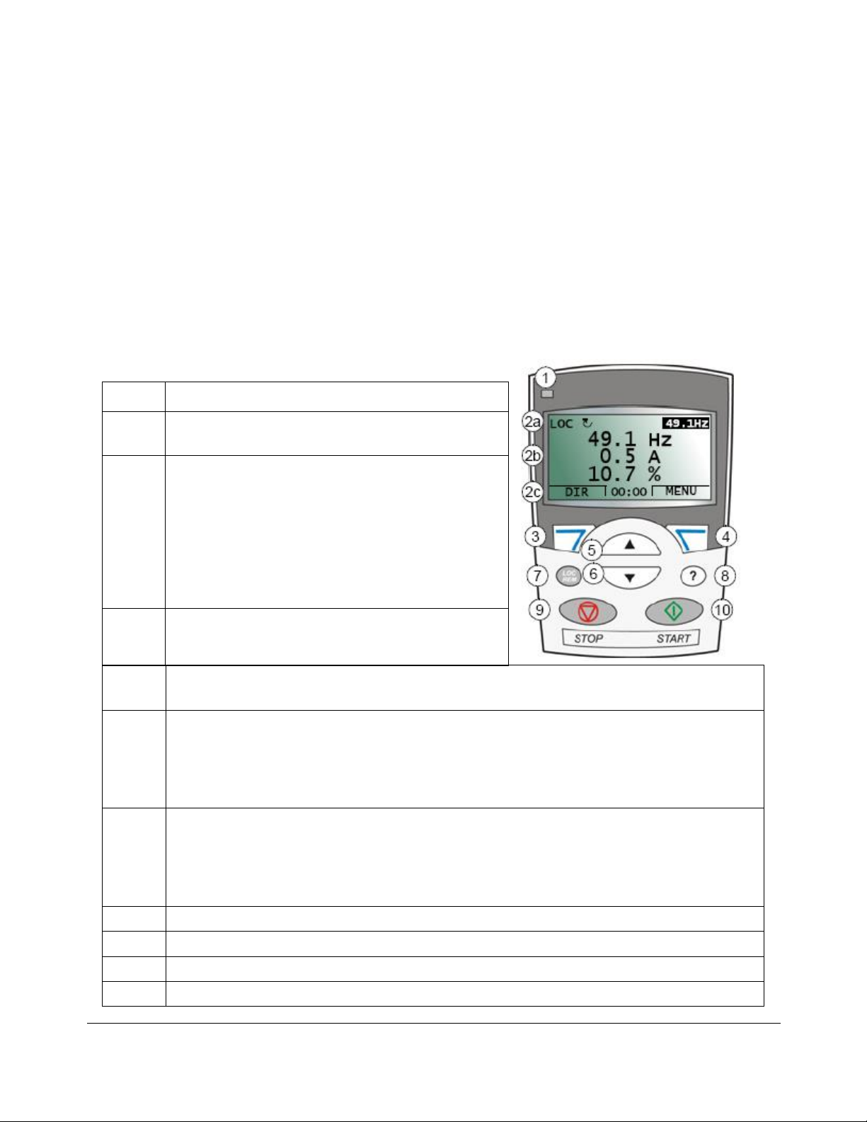
No.
Use
1
Status LED –Green for normal operation. If LED is
flashing or RED check faults.
2
LCD display –Divided into three main areas:
2a: Status line –Shows Remote or Local Mode,
rotation of pump, MAX % setting
2b: Center line –shows parameter values, line 1
psi, line 2 Amps, line 3 Hz
2c: Bottom Line –shows current function of the
two soft keys and if enabled, the clock display
3
Soft key 1 –Function depends on the context. The
text in the lower left corner of the LCD display
indicates the function
4
Soft key 2 –Function depends on the context. The text in the lower right corner of the LCD
display indicates the function
5
Up –
•Scrolls up through a menu or list displayed in the center of the LCD display.
•Increments a value up if a parameter is selected.
•Increments the reference value up if the upper right corner is highlighted.
Holding the key down changes the value faster.
6
Down –
•Scrolls down through a menu or list displayed in the center of the LCD display.
•Increments a value down if a parameter is selected.
•Increments the reference value down if the upper right corner is highlighted.
Holding the key down changes the value faster.
7
LOC/REM –Changes between Local and Remote control of the drive
8
Help –Displays context sensitive information when the key is pressed.
9
STOP –Stops the drive in Local or Remote mode.
10
START –Starts the drive in Local or Remote mode.
Miller-Leaman 800 Orange Ave, Daytona Beach, FL 32114
P: 386.248.0500 F: 386.248.3033 www.millerleaman.com

4
ALARM CODES:
ALARM 2001 – Overcurrent
•Drive detected an overcurrent situation
oCheck Motor load
oCheck acceleration time
oCheck motor and motor cable (including phasing)
ALARM 2002 – Overvoltage
•Drive detected an overvoltage situation
oCheck input power line for static or transient overvoltage
ALARM 2003 – Undervoltage
•Drive detected an undervoltage situation
oCheck input power supply
ALARM 2006 – AI1 Loss
•Analog input AI1 signal (Pressure transducer) has fallen below limit defined by parameter
oCheck pressure transducer connections
oCheck pressure transducer output reading vs inline pressure gauge
ALARM 2008 – Panel Loss
•Control panel has ceased communicating
oCheck Panel connection
oCheck control panel connector (ethernet cable)
oCheck group 10 START/STOP/DIR Settings
ALARM 2010 – Motor Temp
•Motor temp is too high (or appears to be too high) due to excessive load, insufficient motor
power or inadequate cooling.
oCheck motor ratings, load and cooling
ALARM 2018 – PID SLEEP
•Sleep function has entered sleeping mode
oALARM 2018 - PID SLEEP is normal and means that the system has reached maximum
pressure and has sustained that pressure for 30 seconds without any water demand.
Miller-Leaman 800 Orange Ave, Daytona Beach, FL 32114
P: 386.248.0500 F: 386.248.3033 www.millerleaman.com

5
FAULT CODES:
FAULT 0001 – Overcurrent
•Output current has exceeded trip level
oCheck motor load
oCheck motor and motor cable (including phasing)
FAULT 0002 – DC Overvolt
•Excessive intermediate circuit DC voltage. DC overvoltage trip limit is 420v for 200v drives and
840v for 400v drives.
oCheck input power line for static or transient overvoltage.
FAULT 0006 – DC Undervolt
•Intermediate circuit DC voltage is not sufficient.
oCheck input power voltage.
oCheck for missing input power phase.
oCheck fuses.
FAULT 0007 – AI1 Loss
•Analog input AI1 signal (Pressure transducer) has fallen below limit defined by parameter.
oCheck pressure transducer connections.
oCheck pressure transducer output reading vs inline pressure gauge.
FAULT 0009 – Motor Overtemp
•VFD Motor temp is too high (or appears to be too high) due to excessive load, insufficient motor
power or inadequate cooling.
oCheck motor ratings, load and cooling
FAULT 0010 – Panel Loss
•Control panel has ceased communicating
oCheck Panel connection
oCheck control panel connector (ethernet cable)
oCheck group 10 START/STOP/DIR Settings
FAULT 0014 – EXT FAULT 1
•Safety flow switch has triggered ext fault 1. The flow switch is an optional safety feature
available on the ML-VVF systems, it sends the drive into a fault when the pump continues to
run with no water flow for 90 seconds. This is to prevent the pump from overheating.
oCheck flow switch micro switch for damage.
oCheck pump inlet check valve for obstruction (if water can flow back to storage tank
pump will not hold pressure and continue to run with no flow on outlet side)
•*NOTE: The Safety Flow Switch has a built-in auto-restart and will try to reset itself 3 times
before going into a “Hard Fault” and shutting down the system.
FAULT 0016 – Earth Fault
•Drive has Detected earth (ground) fault in motor or motor cable.
oCheck motor.
oCheck Motor cable.
oCheck ground.
Miller-Leaman 800 Orange Ave, Daytona Beach, FL 32114
P: 386.248.0500 F: 386.248.3033 www.millerleaman.com

Table of contents


