Miller Weldmaster Seamrover DD User manual

Instruction Manual
Page 1
This instruction manual is intended to be a guide when operating the Seamrover DD. To ensure optimal
performance from your welder, please follow the recommendations and specifications precisely.
You can also subscribe to Miller Weldmaster Insiders to stay updated on tech tips, machine maintenance
updates, and more at www.weldmaster.com/insiders.

Instruction Manual
Page 2TABLE OF CONTENTS
Chapter 1: Intended Use
Chapter 2: Explanation of Warnings
Chapter 3: Electrical and Air Requirements
Chapter 4: Principles of Heat Sealing
Chapter 5: GPS Tracking and Data Logging System
Chapter 6: Definition of Controls
Chapter 7: Recommended Replacement Parts
Chapter 8: Machine Specifications
Chapter 9: Maintenance
Chapter 10: Transportation Specs and Storage
Chapter 11: Technical Requirements
Chapter 12: Training
Page 3
Pages 4
Page 5
Page 5
Page 6
Page 7-8
Pages 9
Pages 10
Page 11-16
Page 16
Page 16
Page 17
Table of Contents

Instruction Manual
Page 3
1.0 Intended Use
CHAPTER 1 INTENDED USE
The Seamrover DD is a rotary hot air welding machine intended to heat-seal weldable thermal plastics
such as fabric or membrane. Includes PVC, TPO and other weldable material. Always test weld first.
The manufacturer does not approve of:
•Any other uses for these machines.
•The removal of any safety guards while in operation.
•Unauthorized modification of the machines.
•Using replacement parts that are not manufacturer-approved.
Only a properly-trained technician may operate and/or perform any routine
maintenance or repairs to the machines.
NOTE: The manufacturer will not be held liable for any damage or injuries occurring
from any inappropriate use of this machine.
Instruction Manual
Page 4CHAPTER 2 EXPLANATION OF WARNINGS
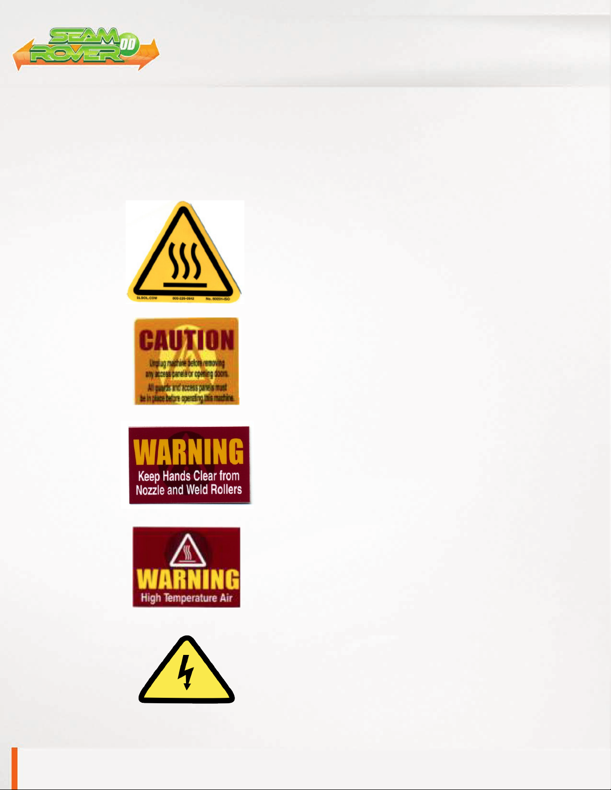
2.0 Explanation of Warnings
There are several different warnings. The warnings are to alert the operator of potentially hazard-
ous areas on the machine. Familiarize yourself with their meaning.
Caution: Unplug Machine
To prevent electrocution, the machine should always
have the power disconnected before the cover is open.
Caution: Electricity
This is a high voltage machine and proper precautions
should be taken during operation and servicing.
Caution: Hot
Areas near the nozzle are hazardous and unsafe to
touch.
Warning: Keep Hands Clear
To prevent any pinching or burns, be aware of the loca-
tion of your hands at all times.
Warning: High Temperature Air
High temperature air is forced though the nozzle as-
sembly and can burn the operator from a distance.

Instruction Manual
Page 5 CHAPTER 3 ELECTRICAL AND AIR REQUIREMENTS
3.0 Electrical and Air Requirements
Warning! Only a qualified electrician may connect the electrical power.
Preparation - World Power
1. Make sure the Power Supply is at 230v, 25amp.
2. Make sure the voltage and current is dedicated to the machine and to the above
specification.
3. Before operation of the machine be sure the surrounding area of the machine is
free of flammable debris. Only authorized persons should be in the area of the
machine while in use.
Electrical Supply
The Miller Weldmaster Seamrover DD requires the following electrical requirements:
•25 Amp - Single phase - 230 Volts
•Recommend a 10k+ generator
4.0 Principals of Heat Sealing
Heat
Hot Air Heating System
The Heat required for the welding operation is created electrically by one heating element locat-
ed inside the Heat Element Housing. The Internal Air Compressor pumps air over the heating
element and carries the heat through the Hot Air Nozzle, applying the heat to the material to
be welded. The hot air temperature ranges from 100 to 1350 Degrees Fahrenheit (25 to 730
Degrees Celsius).
Speed
The Speed of the Weld Rollers determines the amount of time the heat is applied to the material
being welded. The slower the speed setting, the more the material will be heated. The faster the
speed setting, the less the material will be heated. To achieve the best weld, a minimal amount
of heat should be applied to the material while still achieving a full weld. Too much heat will
cause distortion of the material; while not enough heat will prevent the material from welding.
Pressure
The pressure of the weld roller is determined by the weight of the machine on the surface and
is the final step when creating a weld. The pressure of the weld roller compresses the heated
material together completing the welding process.
Summary
When heat sealing, the correct combination of heat, speed, and pressure will allow you to
achieve a properly welded seam.
ALWAYS PERFORM A TEST WELD!

Instruction Manual
Page 6CHAPTER 5 GPS Tracking and Data Logging System Page 6
Instruction Manual
Page 7 CHAPTER 6 DEFINITION OF CONTROLS
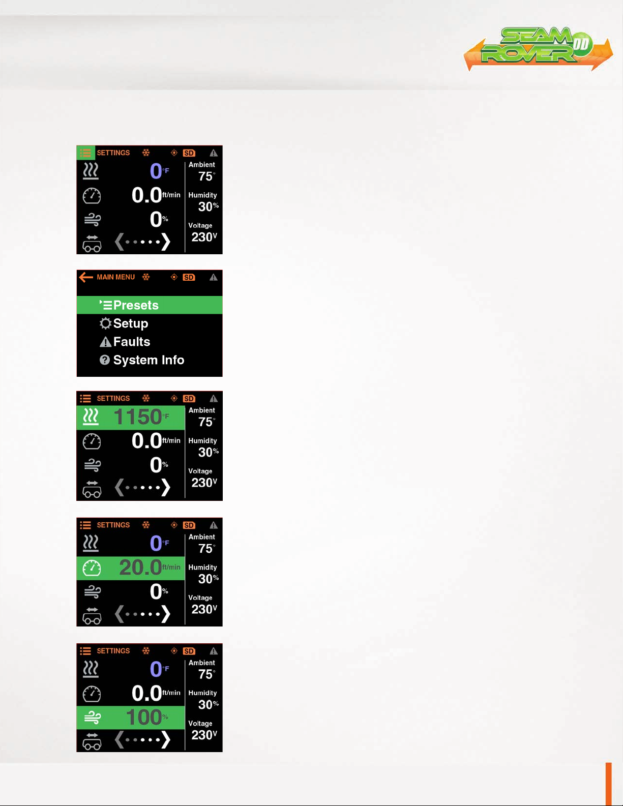
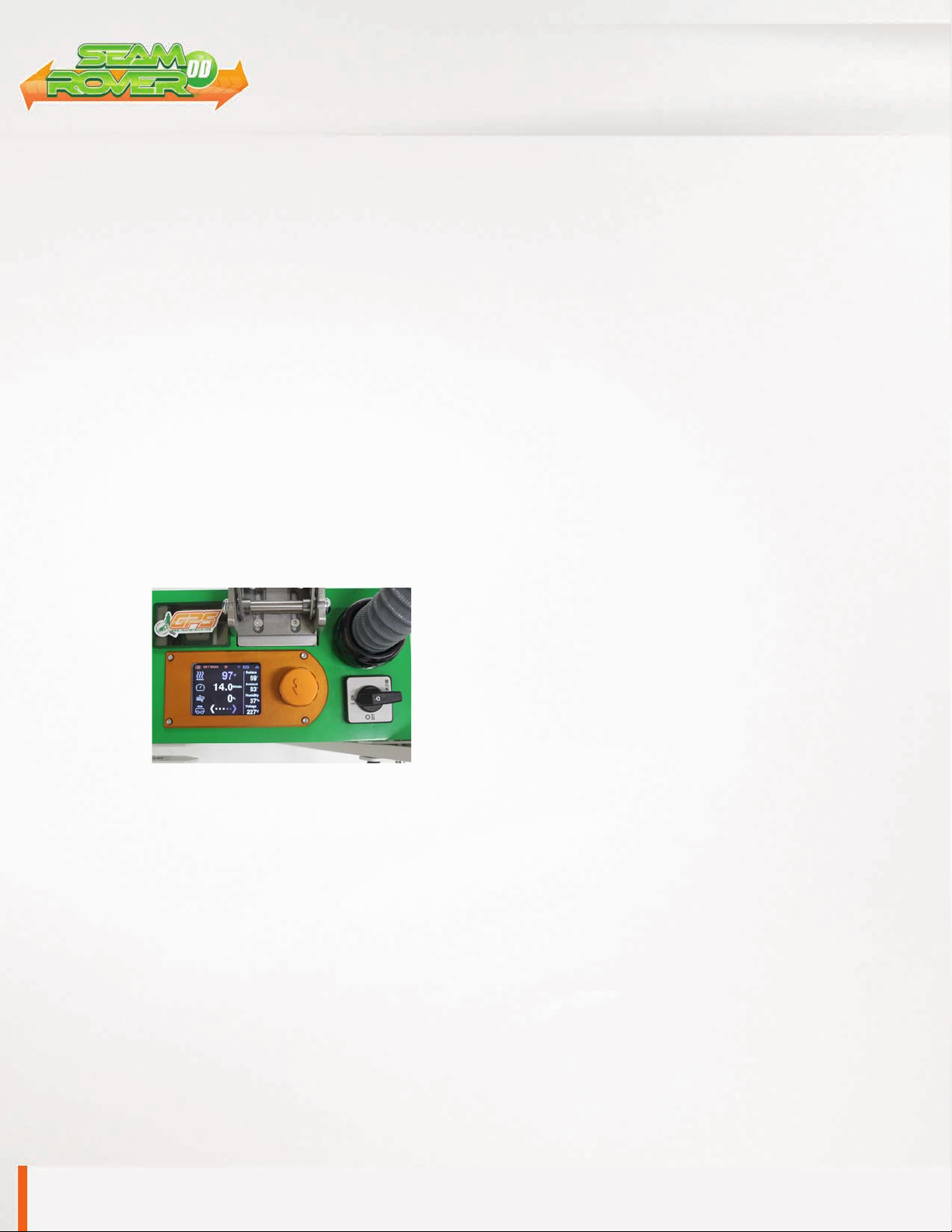
Main Screen - HMI Operation
Presets: This is a particular combination of the parameters of heat and
speed used to weld different types of fabric. This shows which recipe
you’re currently using on the machine. 0 - 15 Available recipe settings.
Machine Speed: This is the speed of the Weld Roller. The speed can be
adjusted by spinning the control knob. Each detent of the knob increases
or decreases the speed by .1ft/min.
Actual Temperature: This is how hot the machine is currently.
Temperature Set Point: This is how hot you want the machine to be for
the purpose of welding your thermal plastics.
6.0 Definition of Controls
Page 7
Home Screen
Menu
Set Heat
Set Speed
Set Blower
Instruction Manual
Page 8CHAPTER 6 DEFINITION OF CONTROLS
6.0 Definition of Controls
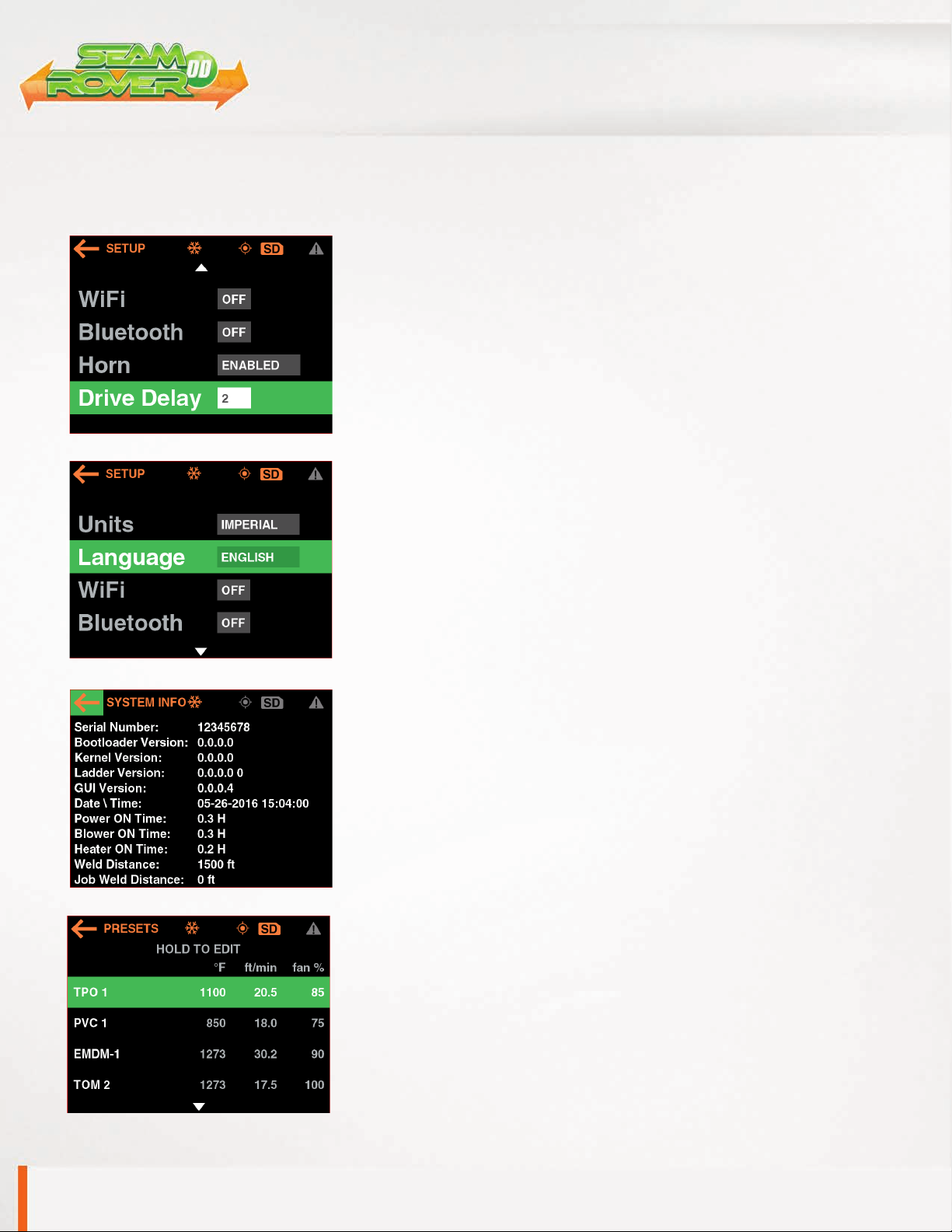
Delay Settings: These are used to eliminate voids in seam. Remember to
test various drive delay settings to ensure quality welds. If the drive delay
is too long the material may be burnt.
Drive Start Delay Time: Once the nozzle swings into position, the Drive
Start Delay Time will delay the weld rollers from turning until the set point
is reached. The Drive Start Delay Time will be adjusted by the operator to
the desired setting.
Language: Select the language according to demand.
MAX Output: 1350˚F 32ft/min 50-100% blower.
Hour Meter: The hour meter will count total time of which the heating
system is on.
Presets: When changing parameters, pressing the SAVE button will save
the adjusted settings to the selected recipe.
Drive Delay
Language
Presets
Hour Meter
Instruction Manual
Page 9 CHAPTER 7 RECOMMENDED REPLACEMENT PARTS
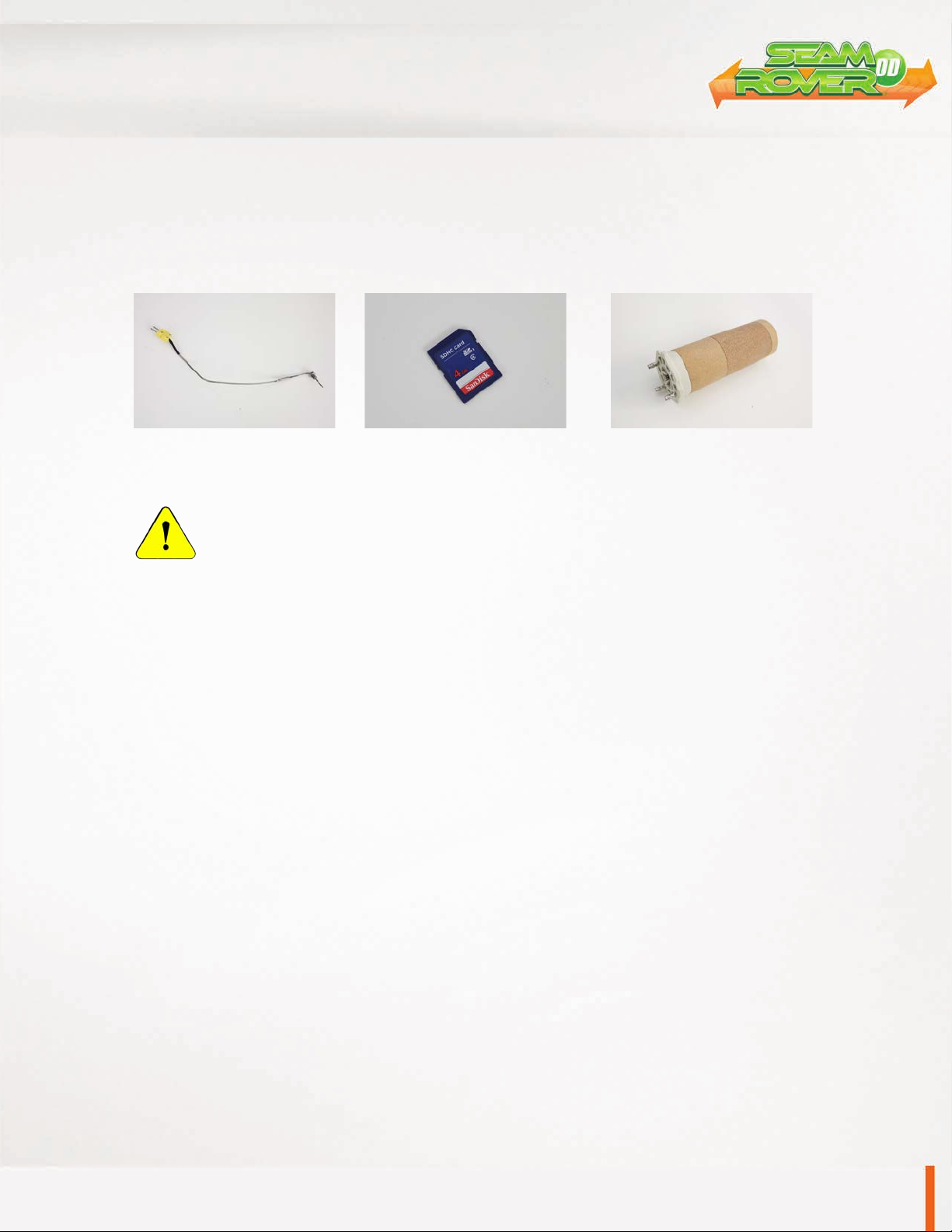
7.0 Recommended Replacement Parts
Miller Weldmaster recommends keeping the following spare parts in stock:
NOTE: The manufacturer will not be held liable for any damage or injuries occurring
from any inappropriate use of this machine.
Instruction Manual
Page 10
CHAPTER 8 MACHINE SPECIFICATIONS
8.0 Machine Specifications
Principles of Operation
The Seamrover DD is a heat sealing machine which welds thermal plastic fabrics or films by Hot Air,
through applying pressure, consistent speed, and accurate temperature for perfectly sealing thermal
plastic materials.
Technical Specifications
•Amp Rating - 25amp at 230volt
•Rated Power - 4600 W
•Rated Voltage - 230v AC, 50/60hz
•Maximum Temperature - 1350°F (730°C)
•Machine Speed - 1-32 ft/min
•Overall Dimensions - 27” x 14” x 13”
•Seam Width - up to 2”
•Net Weight - 88lbs
Operator Controls Section
•Control Panel: The HMI (Human Machine Interface)
Digital Screen allows you to set system controls.
•Power On/Off Switch: Power switch turns the
machine on and off.
Other
•Power Supply Outboard Fuses: Used for the protective control of the General Power Supply
of the complete machine.
•Start/Stop Switch: Controls the starting and stopping of the seaming operation. (Nozzle
Swing)
Instruction Manual
Page 11 CHAPTER 9 MAINTENANCE
9.0 Maintenance
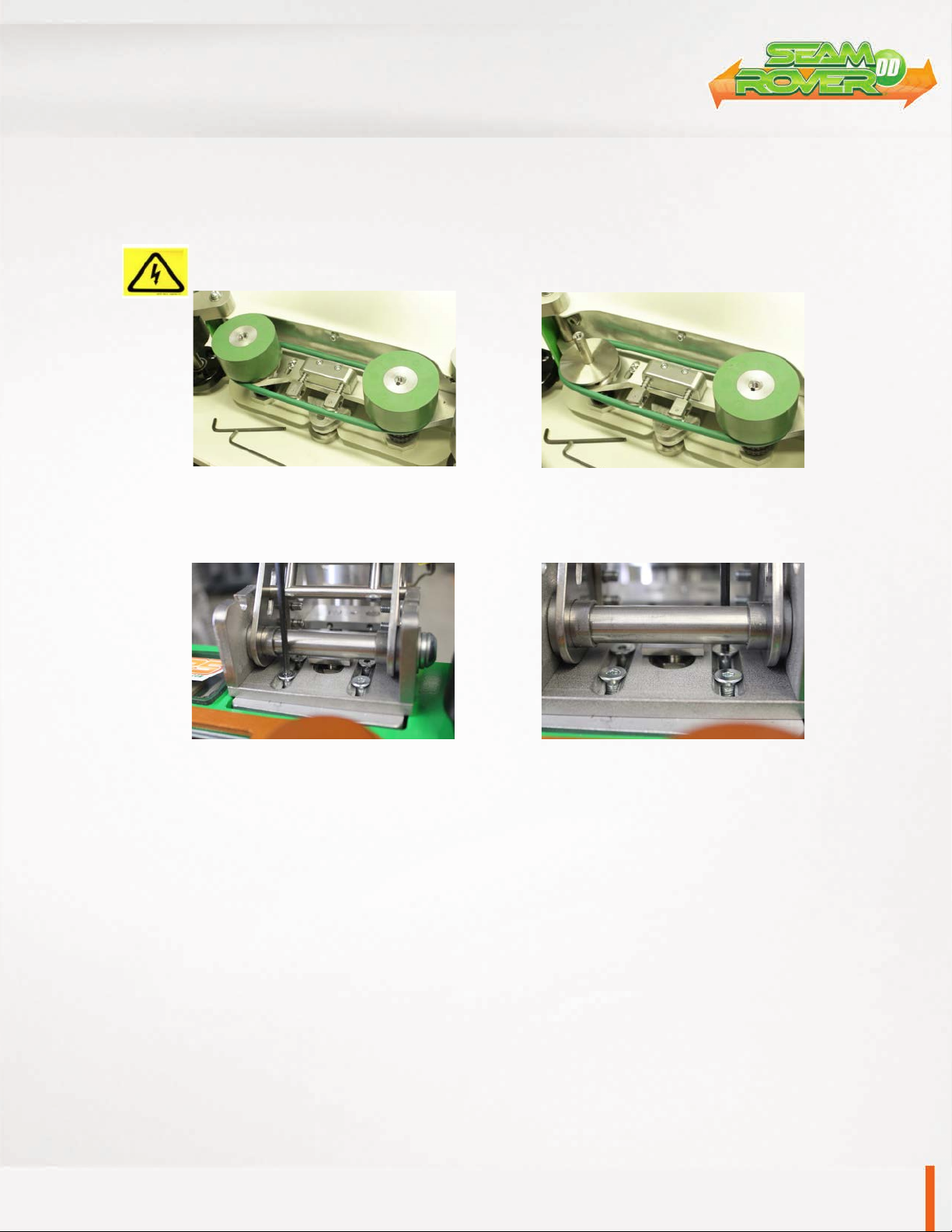
Weld Roller: To replace weld roller remove the fasteners on the drive shaft. Slide the weld roller off the drive
shaft and remove key from key-way. Installation is reverse of removal.
Warning! The operator must disconnect the power from the machine before proceeding.
Nozzle Position (Horizontal): To adjust horizontal nozzle position loosen the four flat head bolts located on
the nozzle mounting bracket. When all four bolts are slightly loose, slide the nozzle into place while applying
downward pressure on the nozzle mounting bracket. Once the nozzle placement is satisfactory, tighten the
bolts in a crisscross pattern starting with one of the bolts closest to the element housing (Fig. 2).
Fig. 1 Fig. 2

Instruction Manual
Page 12
Nozzle Position (Vertical): To adjust vertical nozzle position
locate the socket head cap screw and jam nut underneath the
nozzle float assembly. Break the jam nut loose and drive the
socket head cap screw in or out to adjust the resting position
of the nozzle. Once the nozzle placement is satisfactory, tight-
en the jam nut. Fine tune the vertical nozzle position such that
the nozzle can easily swing into the seam to be welded.
9.0 Maintenance
Thermocouple: Replace the thermocouple by removing the four socket head cap screws on the side of
the element housing. This allows removal of the thermocouple guard. Break the thermocouple free using a
wrench. Cut and remove the protective heat shrink from the thermocouple plug and unplug the thermocou-
ple. Installation is reverse of removal.
CHAPTER 9 MAINTENANCE
Instruction Manual
Page 13
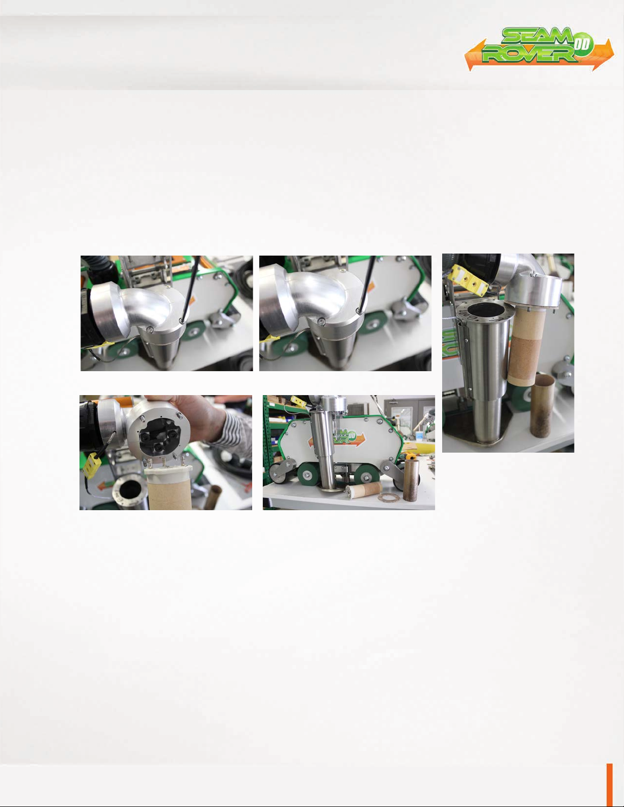
Element: To replace the element loosen and remove the four socket head cap screws from the top of the
element housing cap. Slowly pull the cap directly out of the element housing. Remove the element insulat-
ing tube and the element housing cap gasket and set aside. Now, the element can be unplugged from the
element housing cap. Installation is reverse of removal.
9.0 Maintenance
Step 1 Step 2
Step 3
Step 4 Step 5
CHAPTER 9 MAINTENANCE

Instruction Manual
Page 14CHAPTER 9 MAINTENANCE
9.0 Maintenance
Electrical Circuits
1. When replacing parts and components, you must use the part or components
of the same type as the original or equivalent to the original type. Original
equipment replacement parts should be purchased through Miller Weldmaster
and or a Miller Weldmaster authorize distributor.
2. To avoid damaging the control module, Display and Operating Panel, never plug
or unplug the cables connecting the PLC, Display and Operating Panel while the
power is on.
3. If there is any fault that cannot be removed, please immediately contact the
service department at Industrial Heat Sources (IHS) at +1 (330) 970-9353.
Drive System
1. Check if the Driving Sprockets are dislocated or loosened.
2. Check if the chains are too loose. Tighten as needed.
NOTICE: By not properly maintaining the machine, the performance may be effected. Please
contact Miller Weldmaster with any questions.
Instruction Manual
Page 15 CHAPTER 9 MAINTENANCE
9.0 Maintenance
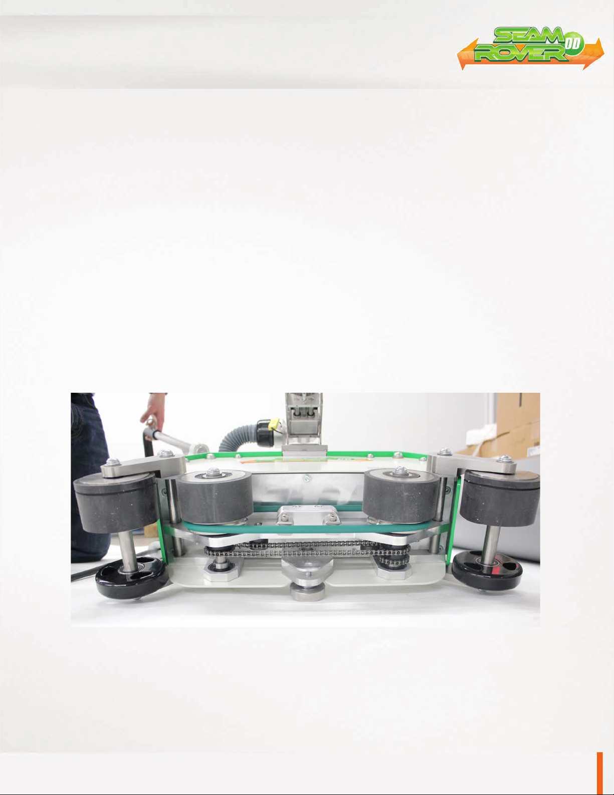
Tightening/Oiling Chains
The Miller Weldmaster Seamrover DD has two chains that are used to drive weld rollers. Although not a high
maintenance item, chains should be inspected once a year to ensure there is not excessive corrosion, rust, or
dirt. Also inspect for any looseness or slack. If needed, lubricate chains once a year with 80w – 90w gear oil.
1. Turn the circuit breaker to the off position.
2. Disconnect the power cord from the power supply.
3. Tilt the machine on it’s side and inspect the chains. Perform any maintenance to the chains as
needed.

Instruction Manual
Page 16CHAPTER 9 MAINTENANCE
9.0 Maintenance
Hot Air Heat System Adjustments
Begin by turning your hot air on and setting to the desired temperature.
1. Depth of your nozzle should be at approximately 1 of an inch from the pinch point
of your weld rollers. If the nozzle is aligned, perform a test weld. If not replace the nozzle
or have machine serviced.
10.0 Transportation Specs and Storage
11.0 Technical Requirements
Storage
The manufacturer recommends that any time the machine is not in use, it must be protected from
excess dust and moisture. The operator should familiarize themselves with the warning symbols on
the machine to be alert to the potentially hazardous areas on the machine.
NOTE: The manufacturer will not be held liable for any damage or injuries occurring from any
inappropriate use of this machine.
Technical Requirements
1. When the Weld Rollers are aligned properly, the edges of the two rollers should
be parallel and aligned.
2. Heat System Swing: The swing in/out of the heat system should be smooth
and natural at moderate speed.
3. Air lines and air fittings should be free of leaks.
NOTE: Changes in factors such as thickness of materials, qualifications of the op-
erators and different environment and weather may directly affect the product. The
operator should be able to understand the following adjustable factors particularly:
1. Heating Temperature
2. The pressure of the Weld Rollers
3. Air volume
4. Placement of heating system
/4
3

Instruction Manual
Page 17
12.0 Training
CHAPTER 12 TRAINING

Instruction Manual
Page 18NOTES
NOTES:_________________________________________________________________
_______________________________________________________________________
_______________________________________________________________________
_______________________________________________________________________
_______________________________________________________________________
_______________________________________________________________________
_______________________________________________________________________
_______________________________________________________________________
_______________________________________________________________________
______________________________________________________________________
_______________________________________________________________________
_______________________________________________________________________
_______________________________________________________________________
_______________________________________________________________________
_______________________________________________________________________
_______________________________________________________________________

Instruction Manual
Page 19
NOTES:_________________________________________________________________
_______________________________________________________________________
_______________________________________________________________________
_______________________________________________________________________
_______________________________________________________________________
_______________________________________________________________________
_______________________________________________________________________
_______________________________________________________________________
_______________________________________________________________________
______________________________________________________________________
_______________________________________________________________________
_______________________________________________________________________
_______________________________________________________________________
_______________________________________________________________________
_______________________________________________________________________
_______________________________________________________________________
NOTES

Instruction Manual
Page 20NOTES
NOTES:_________________________________________________________________
_______________________________________________________________________
_______________________________________________________________________
_______________________________________________________________________
_______________________________________________________________________
_______________________________________________________________________
_______________________________________________________________________
_______________________________________________________________________
_______________________________________________________________________
______________________________________________________________________
_______________________________________________________________________
_______________________________________________________________________
_______________________________________________________________________
_______________________________________________________________________
_______________________________________________________________________
_______________________________________________________________________
Table of contents
Other Miller Weldmaster Welding System manuals

Miller Weldmaster
Miller Weldmaster T-100 User manual

Miller Weldmaster
Miller Weldmaster T600 Extreme User manual

Miller Weldmaster
Miller Weldmaster 112 Extreme User manual

Miller Weldmaster
Miller Weldmaster T3 Extreme User manual

Miller Weldmaster
Miller Weldmaster 112 Extreme User manual

Miller Weldmaster
Miller Weldmaster Impulse 3.0 Extreme User manual

Miller Weldmaster
Miller Weldmaster Triad Extreme User manual

Miller Weldmaster
Miller Weldmaster Extreme T300 User manual


