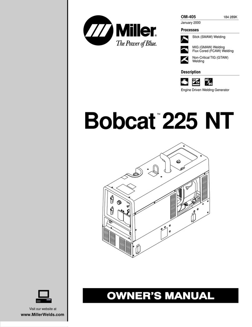
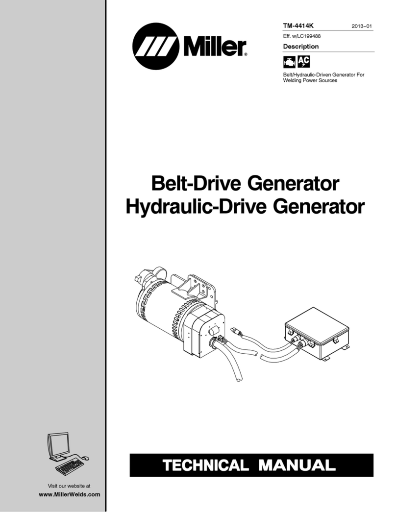
Miller TM-268 User manual

Visit our website at
www.MillerWelds.com
Description
Belt-Driven Generator
TM-268 819A 2014−11
Eff. w/MD040275R And Following
4 kW And 7.5 kW
Belt-Drive Generators

2
TABLE OF CONTENTS
SECTION 1 − SAFETY PRECAUTIONS FOR SERVICING 1........................................
1-1. Symbol Usage 1.......................................................................
1-2. Servicing Hazards 1....................................................................
1-3. California Proposition 65 Warnings 3......................................................
1-4. EMF Information 3.....................................................................
SECTION 2 − DEFINITIONS 4..................................................................
2-1. Additional Safety Symbols And Definitions 4................................................
2-2. Miscellaneous Symbols And Definitions 4.................................................
SECTION 3 − SPECIFICATIONS 5..............................................................
3-1. Description 5..........................................................................
3-2. 4 kW Model Specifications 5.............................................................
3-3. 7.5 kW Model Specifications 5...........................................................
3-4. AC Power Curve 6.....................................................................
SECTION 4 − MAINTENANCE AND TROUBLESHOOTING 7.......................................
4-1. Maintenance Schedule 7................................................................
4-2. Overload Protection 7..................................................................
SECTION 5 − 4 kW MODELS THEORY OF OPERATION 8.........................................
SECTION 6 − 7.5 kW MODELS THEORY OF OPERATION 9.......................................
SECTION 7 − TROUBLESHOOTING 4kW GENERATOR 10.........................................
7-1. Troubleshooting Table 10.................................................................
7-2. Field Flashing 11........................................................................
SECTION 8 − TROUBLESHOOTING 7.5kW GENERATOR 12.......................................
8-1. Troubleshooting Table 12.................................................................
8-2. Troubleshooting Circuit Diagram For Welding Generator 14....................................
8-3. Waveforms For Section 8-2 16............................................................
8-4. Power Board PC1 Testing Information 17...................................................
8-5. Power Board PC1 Test Point Values 17.....................................................
8-6. Control Board PC2 Testing Information 18...................................................
8-7. Control Board PC2 Test Point Values 18....................................................
8-8. Inspecting Brushes, Replacing Brushes, And Cleaning Slip Rings 19............................
8-9. Setting Control Board PC2 For 50 Hz Operation 20...........................................
8-10. Checking Unit Output After Servicing 21....................................................
SECTION 9 − DISASSEMBLY AND REASSEMBLY 22..............................................
9-1. Disassembling/Reassembling 4 kW Generator 22............................................
9-2. Disassembling/Reassembling 7.5 kW Generator 23...........................................
SECTION 10 − ELECTRICAL DIAGRAMS 24......................................................
SECTION 11 − 4 kW MODEL EFF w/ME131503R 34................................................
SECTION 12 − 7.5 kW MODEL EFF w/MD040275R 37..............................................

TM-268 819 Page 1Belt Drive Generator
SECTION 1 − SAFETY PRECAUTIONS FOR SERVICING
Protect yourself and others from injury — read, follow, and save these important safety precautions and operating instructions.
1-1. Symbol Usage OM-268 819A - 2014−06, safety_rtm 2013-09
DANGER! − Indicates a hazardous situation which, if
not avoided, will result in death or serious injury. The
possible hazards are shown in the adjoining symbols
or explained in the text.
Indicates a hazardous situation which, if not avoided,
could result in death or serious injury. The possible
hazards are shown in the adjoining symbols or ex-
plained in the text.
NOTICE − Indicates statements not related to personal injury.
.Indicates special instructions.
This group of symbols means Warning! Watch Out! ELECTRIC
SHOCK, MOVING PARTS, and HOT PARTS hazards. Consult sym-
bols and related instructions below for necessary actions to avoid the
hazards.
1-2. Servicing Hazards
The symbols shown below are used throughout this manual
to call attention to and identify possible hazards. When you
see the symbol, watch out, and follow the related instructions
to avoid the hazard.
Only qualified persons should test, maintain, and repair this
unit.
During servicing, keep everybody, especially children, away.
ELECTRIC SHOCK can kill.
DDo not touch live electrical parts.
DStopengine and remove input power plug from
receptacle(if applicable) before testing or re-
pairing unit unless the procedure specifically
requiresan energized unit.
DInsulateyourself from ground by standing or working on dry insu-
latingmats big enough to prevent contact with the ground.
DDo not leave live unit unattended.
DIf this procedure requires an energized unit, have only personnel
familiarwith and following standard safety practices do the job.
DWhentesting live unit, use the one-hand method. Do not put both
hands inside unit. Keep one hand free.
SIGNIFICANT DC VOLTAGE exists in inverter power
sources AFTER stopping engine.
DStop engine on inverter and discharge input capacitors according
to instructions in Troubleshooting Section before touching any
parts.
MOVING PARTS can injure.
DKeepaway from moving parts such as fans,
belts, and rotors.
DKeep away from pinch points such as drive
rolls.
DHave only qualified people remove doors,
panels, covers, or guards for maintenance
and troubleshooting as necessary.
DKeep hands, hair, loose clothing, and tools
away from moving parts.
DBeforeworking on generator, remove spark plugs or injectors
to keep engine from kicking back or starting.
DBlock flywheel so that it will not turn while working on genera-
tor components.
DReinstall doors, panels, covers, or guards when servicing is
finished and before starting engine.
FLYING METAL or DIRT can injure eyes.
DWear safety glasses with side shields or face
shield during servicing.
DBe careful not to short metal tools, parts, or
wires together during testing and servicing.
STATIC (ESD) can damage PC boards.
DPut on grounded wrist strap BEFORE handling
boards or parts.
DUse proper static-proof bags and boxes to
store, move, or ship PC boards.
Using a generator indoors CAN KILL
YOU IN MINUTES.
DGeneratorexhaust contains carbon monoxide.
This is a poison you cannot see or smell.
DNEVER use inside a home or garage, EVEN IF
doors and windows are open.
DOnly use OUTSIDE and far away from windows, doors, and
vents.
FUEL can cause fire or explosion.
DStopengine and let it cool off before checking or
addingfuel.
DDo not add fuel while smoking or if unit is near
any sparks or open flames.
DDo not overfill tank; clean up any spilled fuel.
FIRE OR EXPLOSION hazard.
DDo not place unit on, over, or near combustible surfaces.
DDo not service unit near flammables.
BATTERY EXPLOSION can BLIND.
DAlways wear a face shield, rubber gloves, and
protective clothing when working on a battery.
DStop engine before disconnecting or connect-
ing battery cables.
DDo not allow tools to cause sparks when working on a battery.
DDo not use welder to charge batteries or jump start vehicles.
DObserve correct polarity (+ and −) on batteries.
DDisconnect negative (−) cable first and connect it last.
BATTERY ACID can BURN SKIN and EYES.
DDo not tip battery.
DReplace damaged battery.
DFlush eyes and skin immediately with water.

TM-268 819 Page 2 Belt Drive Generator
STEAM AND HOT COOLANT can burn.
DIf possible, check coolant level when engine is
cold to avoid scalding.
DAlways check coolant level at overflow tank, if
present on unit, instead of radiator.
DIf the engine is warm, checking is needed, and there is no overflow
tank, follow the next two statements.
DWear safety glasses and gloves and put a rag over radiator cap.
DTurn cap slightly and let pressure escape slowly before completely
removingcap.
ELECTRIC AND MAGNETIC FIELDS (EMF)
can affect Implanted Medical Devices.
DWearers of Pacemakers and other Implanted
MedicalDevices should keep away from serv-
icing areas until consulting their doctor and the
device manufacturer.
FALLING EQUIPMENT can injure.
DUse lifting eye to lift unit and properly installed
accessories only, NOT gas cylinders. Do not
exceed maximum lift eye weight rating (see
Specifications).
DUse equipment of adequate capacity to lift and support unit.
DIf using lift forks to move unit, be sure forks are long enough to
extend beyond opposite side of unit.
DFollowthe guidelines in the Applications Manual for the Revised
NIOSH Lifting Equation (Publication No. 94−110) when manu-
ally lifting heavy parts or equipment.
HOT PARTS can burn.
DDo not touch hot engine parts bare-handed.
DAllow cooling period before working on
equipment.
DTo handle hot parts, use proper tools and/or
wear heavy, insulated welding gloves and
clothingto prevent burns.
TILTING OR TIPPING can injure.
DDo not put any body part under unit while lifting.
DAlways use proper equipment (hoists, slings,
chains, blocks, etc.) of adequate capacity to lift
and support components (stator, rotor, engine,
etc.) as needed during job.
PINCH POINTS can injure.
DBe careful when working on stator and rotor assemblies.
EXPLODING PARTS can injure.
DFailedparts can explode or cause other parts to
explodewhen power is applied to inverters.
DAlways wear a face shield and long sleeves
when servicing inverters.
H.F. RADIATION can cause interference.
DHigh-frequency (H.F.) can interfere with radio
navigation, safety services, computers, and
communicationsequipment.
DHave only qualified persons familiar with elec-
tronic equipment perform this installation.
DThe user is responsible for having a qualified electrician promptly
correct any interference problem resulting from the installation.
DIf notified by the FCC about interference, stop using the equipment
at once.
DHave the installation regularly checked and maintained.
DKeep high-frequency source doors and panels tightly shut, keep
spark gaps at correct setting, and use grounding and shielding to
minimize the possibility of interference.
OVERUSE can cause OVERHEATING.
DAllow cooling period; follow rated duty cycle.
DReduce current or reduce duty cycle before
startingto weld again.
DDo not block or filter airflow to unit.
SHOCK HAZARD from testing.
DStopengine or turn Off welding power source (if
applicable)before making or changing meter
lead connections.
DUse at least one meter lead that has a self-
retainingspring clip such as an alligator clip.
DRead instructions for test equipment.
READ INSTRUCTIONS.
DUse Testing Booklet (Part No. 150 853) when
servicing this unit.
DConsultthe Owner’s Manual for welding safety
precautions.
DUse only genuine replacement parts from the manufacturer.
DReadand follow all labels and the TechnicalManual carefully be-
fore installing, operating, or servicing unit. Read the safety in-
formationat the beginning of the manual and in each section.
DPerform maintenance and service according to the Technical
Manual,industry standards, and national, state, and local codes.
DReinstallinjectors and bleed air from fuel system according to
enginemanual.
HYDRAULIC EQUIPMENT can injur
e
or kill.
DBefore working on hydraulic system, turn of
f
and lockout/tagout unit, release pressure, and
be sure hydraulic pressure cannot be accident-
ally applied.
DDo not work on hydraulic system with unit running unless you are a
qualifiedperson and following the manufacturer’s instructions.
DDo not modify or alter hydraulic pump or manufacturer-supplied
equipment. Do not disconnect, disable, or override any safety
equipmentin the hydraulic system.
DKeepaway from potential pinch points or crush points created by
equipment connected to the hydraulic system.
DDo not work under or around any equipment that is supported only
by hydraulic pressure. Properly support equipment by mechanical
means.
HYDRAULIC FLUID can injure or kill
.
DBeforeworking on hydraulic system, turn off a
nd
lockout/tagoutunit, release pressure, and be su
re
hydraulicpressure cannot be accidentally applie
d.
DRelieve pressure before disconnecting or co
n-
nectinghydraulic lines.
DCheck hydraulic system components and all co
n-
nections and hoses for damage, leaks, and we
ar
before operating unit.
DWear protective equipment such as safe
ty
glasses, leather gloves, heavy shirt and trouse
rs,
high shoes, and a cap when working on hydrau
lic
system.
DUse a piece of paper or cardboard to search f
or
leaks−−never use bare hands. Do not use equ
ip-
mentif leaks are found.

TM-268 819 Page 3Belt Drive Generator
DHYDRAULICFLUID is FLAMMABLE−−do not work on hydraulics
near sparks or flames; do not smoke near hydraulic fluid.
DReinstall doors, panels, covers, or guards when servicing is
finishedand before starting unit.
DIf ANY fluid is injected into the skin, it must be surgically removed
withina few hours by a doctor familiar with this type of injury or gan-
grenemay result.
COMPRESSED AIR EQUIPMENT can
injure or kill.
DBeforeworking on compressed air system, turn
off and lockout/tagout unit, release pressure,
and be sure air pressure cannot be accidentally
applied.
DDo not work on compressed air system with unit running unless
you are a qualified person and following the manufacturer’s in-
structions.
DDo not modify or alter compressor or manufacturer-supplied
equipment. Do not disconnect, disable, or override any safety
equipmentin the compressed air system.
DKeepaway from potential pinch points or crush points created by
equipment connected to the compressed air system.
DDo not work under or around any equipment that is supported only
by air pressure. Properly support equipment by mechanical
means.
COMPRESSED AIR can injure or kill.
DBefore working on compressed air system,
turn off and lockout/tagout unit, release pres-
sure, and be sure air pressure cannot be acci-
dentally applied.
DRelieve pressure before disconnecting or con-
nectingair lines.
DCheck compressed air system components
and all connections and hoses for damage,
leaks, and wear before operating unit.
DDo not direct air stream toward self or others.
DWear protective equipment such as safety glasses, hearing pro-
tection,leather gloves, heavy shirt and trousers, high shoes, and a
cap when working on compressed air system.
DUse soapy water or an ultrasonic detector to search for
leaks−−never use bare hands. Do not use equipment if leaks are
found.
DReinstall doors, panels, covers, or guards when servicing is
finishedand before starting unit.
DIf ANY air is injected into the skin or body seek medical help imme-
diately.
TRAPPED AIR PRESSURE AND WHIPPING
HOSES can injure.
DReleaseair pressure from tools and system be-
fore servicing, adding or changing attach-
ments,or opening compressor oil drain or oil fill
cap.
1-3. California Proposition 65 Warnings
Welding or cutting equipment produces fumes or gases
which contain chemicals known to the State of California to
cause birth defects and, in some cases, cancer. (California
Health & Safety Code Section 25249.5 et seq.)
Battery posts, terminals and related accessories contain lead
and lead compounds, chemicals known to the State of
California to cause cancer and birth defects or other
reproductiveharm. Wash hands after handling.
This product contains chemicals, including lead, known to
the state of California to cause cancer, birth defects, or other
reproductiveharm. Wash hands after use.
For Gasoline Engines:
Engine exhaust contains chemicals known to the State of
Californiato cause cancer, birth defects, or other reproduc-
tive harm.
For Diesel Engines:
Diesel engine exhaust and some of its constituents are
known to the State of California to cause cancer, birth
defects,and other reproductive harm.
1-4. EMF Information
Electric current flowing through any conductor causes localized electric
and magnetic fields (EMF). The current from arc welding (and allied pro-
cesses including spot welding, gouging, plasma arc cutting, and
inductionheating operations) creates an EMF field around the welding
circuit. EMF fields may interfere with some medical implants, e.g. pace-
makers. Protective measures for persons wearing medical implants
have to be taken. For example, restrict access for passers−by or con-
duct individual risk assessment for welders. All welders should use the
following procedures in order to minimize exposure to EMF fields from
the welding circuit:
1. Keep cables close together by twisting or taping them, or using a
cable cover.
2. Do not place your body between welding cables. Arrange cables
to one side and away from the operator.
3. Do not coil or drape cables around your body.
4. Keep head and trunk as far away from the equipment in the
welding circuit as possible.
5. Connect work clamp to workpiece as close to the weld as
possible.
6. Do not work next to, sit or lean on the welding power source.
7. Do not weld whilst carrying the welding power source or wire
feeder.
About Implanted Medical Devices:
Implanted Medical Device wearers should consult their doctor and the
device manufacturer before performing or going near arc welding, spot
welding,gouging, plasma arc cutting, or induction heating operations.
If cleared by your doctor, then following the above procedures is recom-
mended.

TM-268 819 Page 4 Belt Driven Generator
SECTION 2 − DEFINITIONS
2-1. Additional Safety Symbols And Definitions
Movingparts can injure.
Safe100 2012−08
2-2. Miscellaneous Symbols And Definitions
Circuit Breaker Read Operator’s
Manual AAmperes VVolts
Positive Negative Alternating Current
(AC) Output
Time hHours Temperature Protective Earth
(Ground)
Notes

TM-268 819 Page 5
Belt Driven Generator
SECTION 3 − SPECIFICATIONS
3-1. Description
This belt-driven generator supplies ac power to the platform to run tools, lights, and cutting and welding equipment.
All power regulation components are located in a control box that is connected by cable to the generator. The genera-
tor supplies power when running at the specified speed with the Power switch on (switch is located on platform). For
the 4 kW models, a 2-pole, 20 Amp circuit breaker protects the generator from overload. For 7.5 kW models, a 3-pole,
30 Amp circuit breaker protects the generator from overload. The 4 kW model is brushless.
3-2. 4 kW Model Specifications
Drive-Type Output GeneratorSpeed
Belt-Drive/Pulley
Single-Phase, 4 kVA/kW, 20 A,
120/240 V, 60 Hz or
115/230 V, 50 Hz
1.0 Power Factor
100% Duty Cycle
3000 rpm (50 Hz)
3600 rpm (60 Hz)
Generator Dimensions Control Box Dimensions
Length 18-3/4 in (476 mm) Length 11-1/2 in (292 mm)
Width 9-1/4 in (235 mm) Width 9-1/2 in (241 mm)
Height 13 in (330 mm) Height 4-1/2 in (114 mm)
Weight Weight
100 lb (45 kg) 8 lb (4 kg)
3-3. 7.5 kW Model Specifications
Drive-Type Output GeneratorSpeed
Belt-Drive/Pulley
Single-Phase, 6 kVA/kW, 25 A, 120/240 V,
50/60 Hz
1.0 Power Factor
100% Duty Cycle
Three-Phase 7.5 kVA/kW, 18 A,
240 V, 50/60 Hz,
1.0 Power Factor
100% Duty Cycle
3000 rpm (50 Hz)
3600 rpm (60 Hz)
Generator Dimensions Control Box Dimensions
Length 20-1/2 in (521 mm) Length 11-1/2 in (292 mm)
Width 9 in (229 mm) Width 9-1/2 in (241 mm)
Height 13 in (330 mm) Height 4-1/2 in (114 mm)
Weight Weight
110 lb (50 kg) 10 lb (5 kg)

TM-268 819 Page 6 Belt Driven Generator
3-4. AC Power Curve
209 397 / 209 398 / 265 921
The ac power curve shows the
power in amperes available from
the generator.
0
50
100
150
200
250
300
0 5 10 15 20 25 30 35 40 45 50
AC AMPERES
AC VOLTS
0
50
100
150
200
250
300
0 5 10 15 20 25 30 35 40
AC AMPERES
AC VOLTS
0
50
100
150
200
250
300
010203040506070
Voltage (Volts)
Current (Amp)
50HZ
60HZ
4 kW Models
6 kW Single−Phase
7.5 kW Three−Phase
7.5 kW Models

TM-268 819 Page 7
Belt Driven Generator
SECTION 4 − MAINTENANCE AND TROUBLESHOOTING
4-1. Maintenance Schedule
!Stop engine before maintaining.
.Service more often if used in severe conditions.
* To be done by Factory Authorized Service Agent.
Every 250 h
1/2 in.
(13 mm) Check Belt
Tension Replace
Unreadable
Labels.
Every 1000 h
Blow Out Inside Of
Generator.
During Heavy Service
,
Clean Monthly.
Service 7.5 kW
Generator Brushes And
Slip Rings. Service
More Often In Dirty
Conditions.*
7.5 kW Model
!Stop engine.
.When a circuit breaker opens,
it usually indicates a more seri-
ous problem exists. Contact
Factory Authorized Service
Agent.
Open cover to access generator.
1 Circuit Breaker CB1
CB1 protects the generator wind-
ings from overload. If CB1 opens,
generatoroutput stops.
Close covers before operating unit.
4-2. Overload Protection
803 233 / 250 654
1
1
4 kW Model
7.5 kW Model

TM-4414 Page 8 Belt/Hydraulic Drive Generator
1 Engine
Supplies force to turn revolving
field (rotor).
2 Revolving Field (Rotor)
Turns at 3000 rpm (50 Hz) or 3600
rpm (60 Hz). The speed determines
voltagesin stator windings.
3 Stator Windings
Supply power to generator power
circuits.
4 ControlRelay CR1
When12 volts DC (battery voltage)
is applied, CR1 energizes to com-
plete the circuit allowing generator
output.
5 Capacitor C1
Engine speed and capacitor value
determinegenerator output.
6 Generator Power Circuit
Breaker CB1
Protects the generator windings
from overload.
7 Terminals 1T, 2T, 3T
Provides connection point for cus-
tomersupplied equipment and re-
ceptacles.
SECTION 5 − 4 kW MODELS THEORY OF OPERATION
Revolving
Field
(Rotor) Stator Windings
Generator Power
213
6
7
Engine
Circuit
Breaker
CB1
Terminals
1T, 2T,
3T
+12 Volt DC Input Voltage
(Customer-Supplied)
AC Or DC Control Circuits
Mechanical Coupling
Generator Output
Magnetic Coupling
4
Control
Relay
CR1
5
Capacitor
C1

TM-4414 Page 9Belt/Hydraulic-Drive Generator
1 Engine
Supplies force to turn revolving
field (rotor).
2 Revolving Field (Rotor)
Turns at 3000 rpm (50 Hz) or 3600
rpm (60 Hz). The speed and excita-
tion current of the field coils deter-
minevoltages in stator windings.
3 Stator Windings
Supplypower to exciter and gener-
ator power circuits.
4 Power Board PC1
Works with PC2 to adjust output by
changingrevolving field current af-
ter comparing feedback from PC2
to generator open-circuit voltage.
Uses current feedback signal for
currentlimiting circuit to prevent ro-
tor failure from overheating.
5 Control Board PC2
Works with PC1 to regulate revolv-
ing field current. The PWM (pulse
widthmodulation) signal originates
on PC2 and is sent to PC1.
6 Generator Power Circuit
Breaker CB1
Protects the generator windings
from overload.
7 Terminal Block TE1
Provides connection point for cus-
tomersupplied equipment and re-
ceptacles.
SECTION 6 − 7.5 kW MODELS THEORY OF OPERATION
Revolving
Field
(Rotor)
Exciter
Stator Windings
Generator Power
213
Power
Board
PC1
6
7
4
Voltage Feedback Signal
Excitation DC Supply
Engine
Circuit
Breaker
CB1
Terminal
Block
TE1
Control
Board
PC2
5
+12 Volt DC Input Voltage
(Customer-Supplied)
AC Or DC Control Circuits
Mechanical Coupling
Generator Output
Magnetic Coupling

TM-268 819 Page 10 Belt Driven Generator
SECTION 7 − TROUBLESHOOTING 4kW GENERATOR
7-1. Troubleshooting Table
.See Section 7-2 for test points and values and
Section11 and following for parts location.
.Use MILLER Testing Booklet (Part No. 150 853)
when servicing this unit.
.To avoid charges that are not covered under warranty, troubleshoot and replace components as described. Warranty requests on equipment
that could have been repaired in the field or are misdiagnosed may be denied.
Inspect generator and repair or replace components or wiring that shown signs of physical damage.
Inspect stator winding for evidence of overheating. Do not return the generator unless indicated by the troubleshooting guide and factory au-
thorizedservice agent.
Do not return the control box.
Trouble Remedy
No generator output at platform
receptacles. Be sure generator control switch is turned on at platform.
Check and secure electrical connections at platform, generator, and control box.
Be sure all equipment is turned off when starting unit.
Check circuit breaker CB1 for loose terminals. Check continuity across poles of CB1. Reset or replace
CB1 (see Section 4-2).
Check connections at receptacle RC4 Be sure battery voltage is present (12 volts DC) to enable
control relay CR1.
Check control relay CR1: Check all connections, check coil continuity, check for proper coil voltage, and
check contact voltage (input to common and output to common) to ensure contacts are operating. Re-
place CR1 if indicated.
Disconnect stator leads 1, 4, and 90 (if applicable) from circuit breaker CB1, and check continuity bet-
ween leads. Replace generator if indicated.
Check capacitor C1 and replace if indicated.
Excitation of field lost. Flash field according to Section 7-2.
Low generator output at platform
receptacles. Verify generator is running at 3600 rpm for 60 Hz, 3000 rpm for 50 Hz.
Disconnect stator leads 1, 4, and 90 (if applicable) from circuit breaker CB1, and check continuity bet-
ween leads. Replace generator if indicated.
Check capacitor C1 and replace if indicated.
High generator output at platform
receptacles. Verify generator is running at 3600 rpm. for 60 Hz, 3000 rpm for 50 Hz.
Erratic generator output at platform
receptacles. Check and secure electrical connections at platform, generator, and control box.
Verify generator is running at 3600 rpm. for 60 Hz, 3000 rpm for 50 Hz
Check circuit breaker CB1 for loose terminals. Check continuity across poles of CB1. Reset or replace
CB1 (see Section 4-2).

TM-268 819 Page 11
Belt Driven Generator
7-2. Field Flashing
264 721−TPTM1
!Stop generator.
Disconnect plug on wiring enclo-
sure cover. Loosen strain relief
bushing.Remove wiring enclosure
cover.
1 12 Volt Battery
2 Terminal 1T
3 Terminal 2T
4 Battery Negative (−) Lead
5 Battery Positive (+) Lead
6 Circuit Breaker CB1
Be sure CB1 is ON.
Flashthe field by connecting negat-
ive of battery to 2T. With the genera-
tor running, momentarily connect
the battery positive to 1T.
Check for output voltage. If output
voltage is not present, repeat field
flashingprocedure.
When output voltage is available,
stop generator and reinstall cover.
Tools Needed:
2
1
3
4
5
6

TM-268 819 Page 12 Belt Driven Generator
SECTION 8 − TROUBLESHOOTING 7.5kW GENERATOR
8-1. Troubleshooting Table
.See Section 8-2 for test points and values and
Section11 and following for parts location.
.Use MILLER Testing Booklet (Part No. 150 853)
when servicing this unit.
.To avoid charges that are not covered under warranty, troubleshoot and replace components as described. Warranty requests on equipment
that could have been repaired in the field or are misdiagnosed may be denied.
Inspect generator and repair or replace components or wiring that shown signs of physical damage.
Inspect stator winding for evidence of overheating. Do not return the generator unless indicated by the troubleshooting guide and factory au-
thorizedservice agent.
Do not return the control box. Troubleshoot to the circuit board level.
Trouble Remedy
No generator output at platform AC
receptacles. Be sure generator control switch is turned on at platform.
Check and secure electrical connections at platform, generator, and control box.
Be sure all equipment is turned off when starting unit.
Check circuit breaker CB1 for loose terminals. Check continuity across poles of CB1. Reset or replace
CB1 (see Section 4-2).
Check plug PLG3 connection and/or connections at receptacles RC2 and RC4.
Be sure enable voltage (+12 volts DC) is being supplied to control box.
Check slip rings, wiring to brushes, and brush position on slip rings. Install new brushes if indicated. See
Section8-8.
Disconnectleads 12 and 13 from brushes, and check continuity across slip rings (nominal reading is 26
ohms).Replace generator if rotor is open.
Disconnectstator weld leads 1, 2, and 3 from circuit breaker CB1, and check continuity between leads.
Replace generator if indicated.
Disconnectplug PLG4 and check continuity between exciter leads 5 and 6. Replace generator if indicat-
ed.
Check power board PC1 and connections, and replace if indicated (see Section 8-4).
Check control board PC2 and connections, and replace if indicated (see Section 8-6).
Low generator output at platform AC
receptacles. Verify generator is running at 3600 rpm (60 Hz) or 3000 rpm (50 Hz).
If generator voltage is approximately 60 volts (instead of normal 230−240 volts AC), replace control board
PC2.
Check slip rings, wiring to brushes, and brush position on slip rings. Install new brushes if indicated. See
Section8-8.
Disconnectleads 12 and 13 from brushes, and check continuity across slip rings nominal reading is 26
ohms). Replace generator if rotor is open.
Disconnectstator leads 1, 2, and 3 from circuit breaker CB1, and check continuity between leads. Repla-
ce generator if indicated.
Disconnectplug PLG4 and check continuity between exciter leads 5 and 6. Replace generator if indicat-
ed.
Check power board PC1 and connections, and replace if indicated (see Section 8-4).
Check control board PC2 and connections, and replace if indicated (see Section 8-6)..

TM-268 819 Page 13
Belt Driven Generator
Trouble Remedy
High generator output at platform AC
receptacles. Verify generator is running at 3600 rpm (60 Hz) or 3000 rpm (50 Hz).
Check slip rings, wiring to brushes, and brush position on slip rings. Install new brushes if indicated. See
Section8-8.
Check power board PC1 and connections. Check rotor PWM voltage (see Section 8-2 and 8-4) and re-
place if indicated.
Check control board PC2 and connections, and replace if indicated (see Section 8-6).
Erratic generator output at platform AC
receptacles. Check and secure electrical connections at platform, generator, and control box.
Verify generator is running at 3600 rpm (60 Hz) or 3000 rpm (50 Hz).
If generator voltage is approximately 60 volts (instead of normal 230−240 volts AC), replace control board
PC2.
Check circuit breaker CB1 for loose terminals. Check continuity across poles of CB1. Reset or replace
CB1 (see Section 4-2).
Check slip rings, wiring to brushes, and brush position on slip rings. Install new brushes if indicated. See
Section8-8.
Disconnectleads 12 and 13 from brushes, and check continuity across slip rings nominal reading is 26
ohms). Replace generator if rotor is open.
Check power board PC1 and connections, and replace if indicated (see Section 8-4).
Check control board PC2 and connections, and replace if indicated (see Section 8-6).
Notes

TM-268 819 Page 14 Belt Driven Generator
8-2. Troubleshooting Circuit Diagram For Welding Generator
See Section 8-6
for PC2 data
I2
See Section 8-4
for PC1 data
Ridge denotes Pin 1
Ridge denotes Pin 1
PLG1
PLG31
Pin 5 - Circuit Common
I1
Pin 7 Circuit Common
RC1
V13
V12
.Voltage readings taken with
PLG1 connected to RC1 on PC2.
RC31
V11
V10
.Voltagereadings taken with PLG31
connected to RC31 on PC1.
I1 = 1 amps DC (60 Hz)
No greater than 3.5 amps
DC under load
I2 = 1 amps DC (60 Hz)
No greater than 3.5 amps
DC under load

TM-268 819 Page 15
Belt Driven Generator
210 193-B
See Section 8-3 for
waveforms A,B
Test Equipment Needed:
Check Resistance at TE1
C to D,
C to E,
C to F,
E to F,
D to F
All readings should be 1
ohm. Check with lead 42 lift-
ed. Replace generator if
windings are shorted to case
or open.
Waveform A
Pin 1
.Voltage readings taken with PLG4/RC4 connected.
Resistance readings taken with PLG4/RC4 disconnected.
V9
V8
V7
1 ohm
26 ohms
Measure Output Voltages V1
Thru V6 At Basket Receptacle
Voltage Readings
a) Tolerance − ±10% unless
specified
b) Condition − 70°F (21°C); cold
machine (no warm-up); no load
c) Power rpm (3600 at 60 Hz, 3000 at
50 Hz) unless specified
d) Reference − single arrow:
reference to circuit common
(lead 42); double arrow:
reference to points indicated
e) Wiring Diagram − see Section 10
V1 Thru V6 Taken At Basket Receptacle
V1 X to Y − 240 volts AC ±10%
V2 X to Z − 240 volts AC ±10%
V3 Y to Z − 240 volts AC ±10%
V4 X to G − 120 volts AC ±10%
V5 Y to G − 120 volts AC ±10%
V6 Z to G − 208 volts AC ±10%
V7 Rotor:
20 volts DC at no load ±20%
70 volts DC at full load ±10%
V8 Exciter:
138 volts AC at no load ±10%
155 volts AC at full load ±10%
V9 Voltage Feedback:
240 volts AC ±10%
V10 Shutdown Signal:
0 volts DC during normal operation*
V11 PWM Signal: 0 to +15 volts DC
1.5 volts DC normal no load
4.3 volts DC at full load
V12 Generator Enable:
Battery voltage when generator is
enabled (on)
0 volts DC when generator is not en-
abled (off)
V13 Battery Voltage
* If 12 volts DC is present, check rotor
and if rotor checks ok, replace con-
trol board PC1.

TM-268 819 Page 16 Belt Driven Generator
8-3. Waveforms For Section 8-2
Test Equipment Needed:
5 ms 100 V
A. Generator Open-Circuit Voltage, No Load, 60 Hz
5 ms 5 V
B. Pulse Width Modulation (PWM) Signal Between
Power Board PC1 And Control Board PC2 (V11 on
Troubleshooting Circuit Diagram)
gnd
gnd
.The waveforms represent the output
of the generator. When operating
properly, the generator waveforms
match those shown here.
Waveforms shown are for 60 Hertz
models;waveforms for 50 Hertz mod-
els are similar
5
10
15

TM-268 819 Page 17
Belt Driven Generator
8-4. Power Board PC1 Testing Information
803 236 / Ref. 209 400
Be sure plugs are secure before
testing.See Section 8-5 for specific
values during testing.
1 Power Board PC1
2 Receptacle RC31
.Receptacle RC31 was pre-
viously labeled RC14.
Test Equipment Needed:
2
1
8-5. Power Board PC1 Test Point Values
PC1 Voltage Readings
a) Tolerance −
±
10% unless specified
b) Condition − no load; generator run
-
ning at 3000 (50 Hz) or 3600 rpm (6
0
Hz)
c) Reference − to circuit common
(RC31-7) unless noted
Receptacle Pin Value
RC31 1 Pulse Width Modulation (PWM) Signal: +1.5 volts at no load; voltage increases with generator load to
approximately 4.3 volts DC at maximum.
2Shutdown Signal: 0 volts DC during normal operation. If 12 volts DC is present, check rotor and if
rotor checks ok, replace control board PC1.
3+12 volts DC
4Revolving field (rotor): +25 volts DC at no load with respect to RC31-6; +75 volts DC at full load with
respect to RC31-6
5Not used
6Revolving field (rotor): +25 volts DC at no load with respect to RC31-4; +75 volts DC at full load with
respect to RC31-4
7Circuit common
8Exciter: 150 volts AC with respect to RC31-9
9Exciter: 150 volts AC with respect to RC31-8

TM-268 819 Page 18 Belt Driven Generator
8-6. Control Board PC2 Testing Information
803 236 / 207 883-D
Be sure plugs are secure before
testing.See Section 8-5 for specific
values during testing.
1 Power Board PC2
2 Receptacle RC1
Test Equipment Needed:
21
8-7. Control Board PC2 Test Point Values
PC2 Voltage Readings
a) Tolerance −
±
10% unless specified
b) Condition − no load; generator run
-
ning at 3000 (50 Hz) or 3600 rpm (6
0
Hz)
c) Reference − to circuit common
(RC1-5) unless noted
Receptacle Pin Value
RC1 1 Voltage Feedback: 240 volts AC with respect to RC1-2
2Voltage Feedback: 240 volts AC with respect to RC1-1
3Pulse Width Modulation (PWM) Signal: +1.5 volts at no load; voltage increases with generator load to
approximately 4.3 volts DC at maximum.
4Shutdown Signal: 0 volts DC during normal operation. If 12 volts DC is present, check rotor and if
rotor checks ok, replace control board PC1.
5Circuit common
6Revolving field (rotor): +25 volts DC at no load with respect to power board PC1 RC31-4; +75 volts
DC at full load with respect to power board PC1 RC31-4
7+ 12 volts DC
8Enable Line: +12 volts DC when generator is enabled (On); 0 volts DC when generator is not enabled
(Off)
9Revolving field (rotor): +25 volts DC at no load with respect to power board PC1 RC31-4; +75 volts
DC at full load with respect to power board PC1 RC31-4
This manual suits for next models
1
Table of contents
Other Miller Portable Generator manuals

Miller
Miller Metro 300DXQ User manual

Miller
Miller ENPAK User manual

Miller
Miller Subarc DC 650 User manual

Miller
Miller Bobcat 225 NT User manual

Miller
Miller Fusion 160 User manual

Miller
Miller Big Blue 300 PRO Series User manual

Miller
Miller Blue Star 185 User manual

Miller
Miller SubArc AC/DC Digital 1000 Amp User manual

Miller
Miller XMT 450 CC/CV User manual

Miller
Miller Blue Star 145DX User manual