manuals.online logo
Brands
  1. Home
  2. •
  3. Brands
  4. •
  5. Miller
  6. •
  7. Welding System
  8. •
  9. Miller EnPak A60GBHW User manual

Miller EnPak A60GBHW User manual

A60GBHW
Quick Start Guide
Service Locations
Engine Filters
and Fill Points
Fuel Pump
Hydraulic Pump
Compressor
Filters and
Fill Point
Remote/Manual
Switch
CB-1 Location
Cool Pak CB
Location
Fuse and Relay
Panel
Brush Location
Serial Number
Location
1
2
3
4
5
6
7
8
9
10
10
9
5
6
7
2 31 14 4 8
READ INSTRUCTIONS.
• Read and follow all labels and the Owner’s Manual carefully before installing, operating or
servicing unit. Read the safety information at the beginning of the manual and in each section.
WARNING
Control Panel
Start Button
Home Screen
Adjust Control/Select Button
Turning On Unit
Safety interlock signal must be provided to turn unit on. Refer to
section 5-8 in Owner’s Manual for more information.
Press the Start button to turn the Control Panel on. A splash screen
will display for a few seconds before the Home screen is displayed.
Press the Start button to turn on the engine. Use the soft buttons to
open the Weld, Battery, and Settings screens.
Turning Off Unit
Press the Start button to turn the unit off.
Turning Off Control Panel
Hold the Start button for 2 seconds to turn the control panel off.
Control panel will display “Shutting Down” and turn off after a few
seconds along with stopping the engine if running.
2
1
2
3
3 1
Top Status Bar
Status Bar Text
Displays user feedback and any active alerts
and errors.
Glow Plug Icon
Lit when the glow plugs are activated before
cranking.
Auto Start/Stop Icon
Lit when Auto Start/Stop is enabled.
Gauges
RPM Gauge
Displays engine RPM. When unit is stopped,
“OFF” is highlighted. When unit is Auto
Stopped, “READY” is highlighted.
Air Compressor PSI Gauge
The MIN and MAX air compressor PSI
settings are indicated by tick marks.
Chassis Power Gauge
When Chassis Power is not providing output,
gauge shows chassis battery voltage.
If unit is not running, Auto Start/Stop is
enabled, and chassis battery voltage drops
below 12.3 volts, the unit will Auto Start.
When Chassis Power is providing output,
gauge shows chassis power amperage
output.
Engine Load Gauge
Displays current load on the engine. When
gauge reads near or above max, the engine
power is maxed out.
Hydraulics Gauge
Displays hydraulic output (hydraulic
units only).
Battery Charge Gauge
Displays battery charge current output.
Bottom of gauge shows whether the unit is
in 12V or 24V mode.
When output is above 100A, “BOOST”
illuminates.
Soft Buttons
Weld Operation Button
Opens the Weld screen (weld units only).
Battery Charge Operation Button
Opens the Battery Charge screen. On the
Battery Charge screen, the user can start
and stop battery charge and change
12V/24V operation.
Air Compressor Operation Button
Turns air compressor On or Off.
Settings Button
Press to access System Settings,
Maintenance, and System Info screens.
1
2
3
4
5
6
Settings Menu
System Settings
Select to change unit operation parameters.
Maintenance Menu
Select to check, change, or reset the
maintenance interval schedule.
System Info
Select to check and update software, check
and download summary file, and restore unit
to factory defaults.
Troubleshooting
Displays live unit data for troubleshooting
purposes.
1
2
3
4
Home Screen
1 2 3
4 5 6
7
10 11 12 13
89
7
8
10
11
12
13
9
1
2
3
4
To Change System Settings
Step 1: Rotate Adjust Control/Select button to select a setting.
Step 2: Press Adjust Control/Select button on desired setting.
Step 3: Rotate Adjust Control/Select button to update the setting.
Step 4: Press Adjust Control/Select button to
save the setting, or press the Back button to discard setting change.
Press HOME button to return to Home screen.
Air Compressor Operation
Air Compressor Operation Button
While in the Home screen and the Weld screen, press
the Air Compressor Operation button to toggle the
compressor output.
Compressor is On when AIR icon is white, and Off when
AIR icon is gray.
NOTE: Weld output and generator power may be reduced when the air
compressor is on.
1
1
System Settings
System Settings Item Selectable Item Options Description
Power Priority – Optimizes output priority between hydraulics and air compressor.
Air Pressure Min 90 psi up to 10 psi less than max pressure Minimum pressure to start air compressor (adjustable in 1 psi increments).
Air Pressure Max 175 psi down to 10 psi greater than Maximum pressure to stop air compressor (adjustable in 1 psi increments). Lower is better to conserve
min pressure engine power.
Air Response Low, Medium, High Optimizes the response when a heavy air load is applied instead of waiting to turn the air compressor
on when the minimum psi threshold is met.
Auto Start/Stop Enabled / Disabled Engine will stop when no load is applied for the Auto Start/Stop Time threshold. Engine will start again
NOTE: Enabled is recommended. when a load is applied.
Auto Start/Stop Time 2 to 30 minutes How long the unit will run before Auto Stopping with no load.
RPM Auto Idles at 1800 rpm and adjusts based on demand.
2800 Locked at 2800 rpm.
Screen Brightness 1 to 10 Changes the brightness of the display.
Hydraulic Max Pressure 2000 to 4000 psi Maximum hydraulic pressure set point.
NOTE: Compensator is factory set to 3300 psi. If setting maximum pressure above 3300 psi factory setting, a Factory Authorized Service agent will
need to adjust compensator.
Hydraulic Max Flow 3 to 20 gpm NOTE: Set to 8 gpm for most cranes. Maximum hydraulic flow set point. Never set hydraulic flow higher than crane rating.
Crane Remote Type 0V to 12V Step Chooses crane remote signal type.
0V to 12V Proportional
12V to 0V Proportional
Crane Voltage Threshold 0.1V to 12V Optimizes voltage threshold for OFF vs ON.
NOTE: If unit does not idle down •For "0V to 12V Step" and "0V to 12V Proportional" crane remotes, set Crane Voltage Threshold to 0.1V.
when all loads are off, increase the •For IMT Cranes, set Crane Voltage Threshold higher than 0.1V to allow unit to idle down when crane
Crane Voltage Threshold slightly is not enabled.
until unit idles down. •For "12V to 0V Proportional" crane remotes, set Crane Voltage Threshold to slightly less than 12V.
Tap To Start (Weld Units Only) Enabled / Disabled Enabled: Restarts engine while in Auto Stop mode by tapping welding rod to workpiece.
NOTE: Enabled is recommended. Disabled: Engine does not restart by tapping welding rod.
Safe Start Enabled / Disabled Enabled: When in weld screen or battery charge mode, unit will automatically switch to Chassis Power
NOTE: Enabled is recommended. when chassis battery voltage drops below 12.3 volts.
Disabled: Unit does not automatically switch to Chassis Power.
Power Time 1 to 20 minutes Adjustable timeout for automatic switch to Chassis Power.
MillerWelds.com
#294931 ©2023 MillerElectric Mfg. LLC
Maintenance
Service Intervals
Change service intervals or reset interval
countdown here.
The Maintenance screen displays engine
and compressor hours for the unit and
allows the user to reset oil change hours
and change the interval (only shorter than
recommended).
Hours Before Next Oil Change
Required For Each Component
Press the Home button to go to the Home
screen. Press the Back button to go to the
Menu screen.
1
Label located under the top cover.
Service intervals, filters and filter kit part
numbers are all listed here for reference.
Additional information and details are
available in the owner’s manual.
Record Serial Number Of Your Unit
Contact your Upfitter for service or questions.
Upfitter
Service Contact
Phone
Email
Maintenance Label
1

Other Miller Welding System manuals

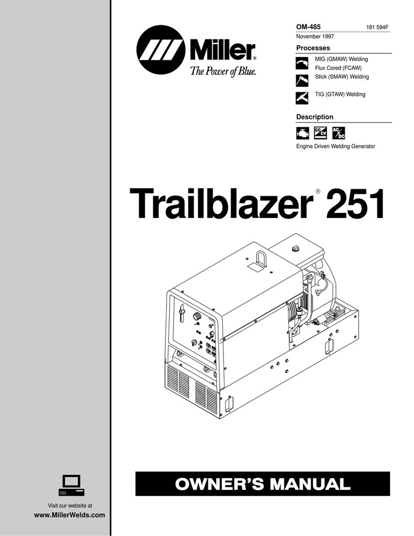
Miller Trailblazer 325 User manual

Miller

Miller Trailblazer 325 User manual

Miller Shielded Metal Arc Welding Instruction Manual

Miller

Miller Shielded Metal Arc Welding Instruction Manual

Miller Blue Thunder Series User manual

Miller

Miller Blue Thunder Series User manual

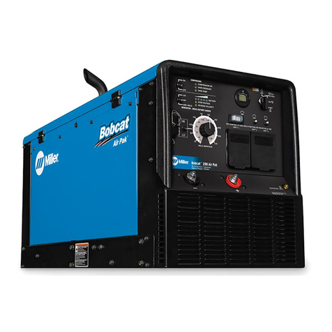
Miller Bobcat 200 Air Pak User manual

Miller

Miller Bobcat 200 Air Pak User manual

Miller XMT 450 CV User manual

Miller

Miller XMT 450 CV User manual

Miller Renegade 180 User manual

Miller

Miller Renegade 180 User manual

Miller Intellifire 250 User manual

Miller

Miller Intellifire 250 User manual

Miller Trailblazer 302 Diesel User manual

Miller

Miller Trailblazer 302 Diesel User manual

Miller AlumaPower 350 MPa User manual

Miller

Miller AlumaPower 350 MPa User manual

Miller Summit Arc 1250 User manual

Miller

Miller Summit Arc 1250 User manual

Miller Big Blue 251D User manual

Miller

Miller Big Blue 251D User manual

Miller Maxstar 140 STR User manual

Miller

Miller Maxstar 140 STR User manual

Miller SQUAREWAVE 1000 User manual

Miller

Miller SQUAREWAVE 1000 User manual

Miller MigMatic 300 User manual

Miller

Miller MigMatic 300 User manual

Miller Big Blue 300 D User manual

Miller

Miller Big Blue 300 D User manual

Miller Dynasty 300 SD User manual

Miller

Miller Dynasty 300 SD User manual

Miller MTXC 3501M Robot Gun User manual

Miller

Miller MTXC 3501M Robot Gun User manual

Miller GA-4OGL User manual

Miller

Miller GA-4OGL User manual

Miller Multimatic 220 AC/DC User manual

Miller

Miller Multimatic 220 AC/DC User manual

Miller Big Blue 450 Duo CST User manual

Miller

Miller Big Blue 450 Duo CST User manual

Miller STi 160 User manual

Miller

Miller STi 160 User manual

Miller Axcess 300 User manual

Miller

Miller Axcess 300 User manual

Miller XMT 300 CC/TIG User manual

Miller

Miller XMT 300 CC/TIG User manual

Miller Big Blue 500X Pro User manual

Miller

Miller Big Blue 500X Pro User manual

Popular Welding System manuals by other brands

ESAB Aristo Mig WeldCloud U5000i instruction manual

ESAB

ESAB Aristo Mig WeldCloud U5000i instruction manual

WTC MedWeld 5000 Technical reference manual

WTC

WTC MedWeld 5000 Technical reference manual

WELDMARK TIG200 owner's manual

WELDMARK

WELDMARK TIG200 owner's manual

CIGWELD 2RT TRANSMIG operating manual

CIGWELD

CIGWELD 2RT TRANSMIG operating manual

Abicor Binzel ABIPLAS CUT 200 W/MT operating instructions

Abicor Binzel

Abicor Binzel ABIPLAS CUT 200 W/MT operating instructions

Lincoln POWER MIG 300 Operator's manual

Lincoln

Lincoln POWER MIG 300 Operator's manual

Thermal Dynamics PAK Master 150XL Service manual

Thermal Dynamics

Thermal Dynamics PAK Master 150XL Service manual

Hobart Welding Products Champion Elite 225 owner's manual

Hobart Welding Products

Hobart Welding Products Champion Elite 225 owner's manual

AMP Command Pro iii 9500 operating manual

AMP

AMP Command Pro iii 9500 operating manual

Thermal Dynamics Pak Master 100XL operating manual

Thermal Dynamics

Thermal Dynamics Pak Master 100XL operating manual

WELDPRO TIGACDC200GD Operator's manual

WELDPRO

WELDPRO TIGACDC200GD Operator's manual

MAC TOOLS TIGW 150/230 V owner's manual

MAC TOOLS

MAC TOOLS TIGW 150/230 V owner's manual

IVT WM-130 manual

IVT

IVT WM-130 manual

TER SRL Multi Synergic 280 instruction manual

TER SRL

TER SRL Multi Synergic 280 instruction manual

Lincoln Electric RED-D-ARC LN-25 PRO EXTREME Operator's manual

Lincoln Electric

Lincoln Electric RED-D-ARC LN-25 PRO EXTREME Operator's manual

Lincoln Electric PRO-CUT 25 Operator's manual

Lincoln Electric

Lincoln Electric PRO-CUT 25 Operator's manual

Furukawa electric S124 user manual

Furukawa electric

Furukawa electric S124 user manual

EWM Microplasma 25 operating instructions

EWM

EWM Microplasma 25 operating instructions

manuals.online logo
manuals.online logoBrands
  • About & Mission
  • Contact us
  • Privacy Policy
  • Terms and Conditions

Copyright 2025 Manuals.Online. All Rights Reserved.