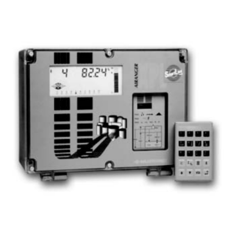
Milltronics smartlinx User manual

Instruction Manual February 2003
REMOTE I/O
smartlinx interface module
R

© Siemens MilltronicsProcessInstruments Inc. 2003
Safety Guidelines
Warning notices must be observed to ensure personal safety as well as that of others, and to
protect the product and the connected equipment. These warning notices are accompanied
by a clarification of the level of caution to be observed.
Qualified Personnel
This device/system may only be set up and operated in conjunction with this manual.
Qualified personnel are only authorized to install and operate this equipment in accordance
with established safety practices and standards.
Warning: This product can only function properly and safely if it is correctly transported,
stored, installed, set up, operated, and maintained.
Note: Always use product in accordance with specifications.
Copyright Siemens Milltronics Process
Instruments Inc.2003.AllRights ReservedDisclaimer of Liability
This document is available in bound version and in
electronic version. We encourage users to
purchase authorized bound manuals, or to view
electronic versions as designed and authored by
Siemens Milltronics Process Instruments Inc.
Siemens Milltronics Process Instruments Inc. will
not be responsible for the contents of partial or
whole reproductions of either bound or electronic
versions.
While we have verified the contents of
this manual for agreement with the
instrumentation described, variations
remain possible. Thus we cannot
guarantee full agreement. The
contents of this manual are regularly
reviewed and corrections are included
in subsequent editions. We welcome
all suggestions for improvement.
Technical data subject to change.
MILLTRONICS®is a registered trademark of Siemens Milltronics Process Instruments Inc.
Contact SMPI Technical Publications at the following address:
Technical Publications
Siemens Milltronics Process Instruments Inc.
1954 Technology Drive, P.O. Box 4225
Peterborough, Ontario, Canada, K9J 7B1
Email: techpubs@milltronics.com
For the library of SMPI instruction manuals, visit our Web site: www.milltronics.com

i
mmmmm
Table of Contents
Table of Contents
Table of Contents .................................................................................................................i
SmartLinx Remote I/O… ...................................................................................................1
Safety Notes .............................................................................................................................................2
The Manual ...............................................................................................................................................2
Specifications ......................................................................................................................3
Installation ...........................................................................................................................4
Compatibility .............................................................................................................................................4
Software Compatibility ................................................................................................................4
Hardware Compatibility ...............................................................................................................5
Cable Connector ......................................................................................................................................7
Termination Switch .................................................................................................................................9
Reserved Switch ............................................................................................................................9
Operation ............................................................................................................................10
Communications Setup ....................................................................................................11
Recommendations ................................................................................................................................11
Specific Parameters .............................................................................................................................13
P751 Baud Rate ............................................................................................................................13
P752 Rack Number ......................................................................................................................13
P753 Starting Group ....................................................................................................................13
P754 Rack Size .............................................................................................................................13
P755 Last Rack .............................................................................................................................14
Map Element Selection .......................................................................................................................14
P762 Map Element Selection parameter ...............................................................................14
Module Identification ...........................................................................................................................16
P794 SmartLinx Module Type ...................................................................................................16
P795 SmartLinx Protocol ............................................................................................................16
P634: Communication Totalizer Resolution .....................................................................................17
Application Layer ..............................................................................................................18
Parameter Indexes ................................................................................................................................18
Primary Index ...............................................................................................................................19
Secondary Index ..........................................................................................................................20
Data Access Methods ..........................................................................................................................20
Direct Access ...............................................................................................................................20
Multiple Parameter Access (MPA) ........................................................................................21
Single Parameter Access (SPA) ..............................................................................................22
Data Map – Level Products ................................................................................................................24
Level Products – Block Transfers ............................................................................................24
Write Block ...................................................................................................................................24
Read Block ....................................................................................................................................27
Level Products – Discrete I/O ...................................................................................................30
Discrete Output Image Table ....................................................................................................31

ii
mmmmm
Table of Contents
Discrete Input Image Table .......................................................................................................33
Data Map: Mass Dynamics Products ..............................................................................................35
Write Block ...................................................................................................................................35
Read Block ....................................................................................................................................39
Data Types ...............................................................................................................................................45
Integer ............................................................................................................................................45
Bit Values .......................................................................................................................................45
Unsigned Double Precision Integer (UINT32) ......................................................................46
Split Values ...................................................................................................................................46
Text Messages .............................................................................................................................47
Relay Function Codes (P111 in Level Products Only) ........................................................48
Troubleshooting .................................................................................................................50
Generally .................................................................................................................................................50
Specifically ..............................................................................................................................................50
Technical Support or Product Feedback .........................................................................................52
Appendix A – Reducing the amount of data being transferred over the Bus .......53
Level Products ........................................................................................................................................53
Write Block ...................................................................................................................................54
Read Block ....................................................................................................................................56
Mass Dynamics Products ...................................................................................................................58
Write Block ...................................................................................................................................59
Read Block ....................................................................................................................................61
Index 63

7ML19981AP03 SmartLinx Remote I/O – INSTRUCTION MANUAL Page 1
mmmmm
SmartLinx Remote I/O
SmartLinx Remote I/O…
The Siemens Milltronics SmartLinx1module for Allen-Bradley Remote I/O is a plug-in
communications card designed to interface a Siemens Milltronics SmartLinx compatible
instrument to an Allen-Bradley Remote I/O network.
Only those instruments which support the Remote I/O protocol can use this card. See
Compatible Instruments
: on page 9 for a list of compatible host instruments.
Remote I/O is an industry standard protocol owned by Allen-Bradley®which is part of
Rockwell Automation. For a full description of the Remote I/O protocol, contact Rockwell
or visit their web site at www.rockwell.com.
Technical Support and Product Feedback
For product feedback or technical support, please contact your local Siemens Milltronics
1. SmartLinx® is a registered trademark of Siemens MIlltronics Process Instru-
ments Inc.
Note: Siemens Milltronics does not own the Remote I/O protocol. All information
regarding that protocol is subject to change without notice.
Allen-Bradley PLC
Remote I/O bus
Siemens Milltronics
Instruments

Page 2 SmartLinx Remote I/O – INSTRUCTION MANUAL 7ML19981AP03
mmmmm
SmartLinx Remote I/O
Safety Notes
Special attention must be paid to warnings and notes highlighted from the rest of the text
by grey boxes.
The Manual
This manual will help you install and connect a Siemens Milltronics SmartLinx-DP
module, and set it up for communication with a master device on a Remote I/O network.
The manual is targeted at a technical audience in the industrial communications field
with a sound working knowledge of Remote I/O. (Please see next page for more details.)
We always welcome questions, comments, or suggestions about manual content, design,
and accessibility.
Please direct your questions or comments to techpubs@siemens -milltronics.com. For the
complete library of Siemens Milltronics manuals, go to www.siemens-milltronics.com.
WARNING: relates to a caution symbol on the product, and means
thatfailureto observethe necessaryprecautions canresultindeath,
serious injury, and/or considerable material damage.
WARNING: means that failure to observe the necessary precautions
can result in death, serious injury, and/or considerable material
damage.
CAUTION: means that failure to observe the necessary precautions can
result in considerable material damage.
Note: means important information about the product or that part of the operating
manual.
Notes:
• Please follow the installation and operating procedures for a quick, trouble-free
installation and to ensure the maximum accuracy and reliability of your Siemens
Milltronics SmartLinx Remote I/O module.
• This manual applies to the SmartLinx Remote I/O module only.

7ML19981AP03 SmartLinx Remote I/O– INSTRUCTION MANUAL Page 3
mmmmm
Speicifcaions
Specifications
Application:
• compatible with master devices on an Allen-Bradley Remote I/O bus
Compatible Instruments:
• AiRanger XPL Plus / SITRANS LU 10
• AiRanger DPL Plus / SITRANS LU 02
• AiRanger SPL / SITRANS LU 01
•CraneRanger
• InterRanger DPS 300
• EnviroRanger ERS 500
• MultiRanger 100/200
•HydroRanger200
Mass Dynamics
• Milltronics BW500
• Milltronics SF500
Communication Settings:
• baud rate: 57.6, 115.2, or 230.4 Kbaud
• starting group: ¼ to full rack
• rack size: ¼ to full rack
Connection:
• 3-position terminal block for wire end
Termination:
• switch selectable, open or 82 Ωinternal
Cable:
• Belden 9463 “Blue Hose” or equivalent

Page 4 SmartLinx Remote I/O – INSTRUCTION MANUAL 7ML19981AP03
mmmmm
Installation
Installation
The SmartLinx module is either shipped installed in the Siemens Milltronics instrument or
shipped separately for on-site installation. Refer to the manual of your Siemens
Milltronics instrument for details on module location and physical installation.
Compatibility
For the SmartLinx Profibus card there are different hardware and software configurations
available depending on the equipment used.
Software Compatibility
If a device is SmartLinx ready, it will work with the correct SmartLinx card for that device.
However, if the firmware version is a lower number than the one listed below, the P762
Map Element Selection Parameter will not be available. Also, for the BW500 and the
SF500, the read block will be a smaller size.
Retrofits:
If you are replacing an older SmartLinx device with a new SmartLinx device, and you are
using any product other than the BW500 or SF500, then you can use the default values for
P762.
If you are replacing a BW500 or SF500 with a new device, then set P762 primary index
15 = 0, and P762 primary index 16 = 0.
Product Software Rev. Product Software Rev.
AiRanger XPL Plus /
SITRANS LU 10
5.23
Milltronics SF500
3.05
AiRanger DPL Plus /
SITRANS LU 02 Milltronics BW500
AiRanger SPL /
SITRANS LU 01 MultiRanger 100 1.04
InterRanger DPS 300 MultiRanger 200 1.03
HydroRanger 200
EnviroRanger ERS 500 5.06

7ML19981AP03 SmartLinx Remote I/O – INSTRUCTION MANUAL Page 5
mmmmm
Installation
Hardware Compatibility
All available SmartLinx card configurations are shown here for reference.
The cardshown below is compatible with the following Siemens
Milltronics units:
• AiRanger XPL Plus / SITRANS LU 10
• AiRanger DPL Plus / SITRANS LU 02
• AiRanger SPL / SITRANS LU 01
•CraneRanger
• InterRanger DPS 300
module connector (underside) to Siemens Milltronics host instrument
mounting hole
mounting hole
reserved switches
status LEDs
termination switch
cable connector

Page 6 SmartLinx Remote I/O – INSTRUCTION MANUAL 7ML19981AP03
mmmmm
Installation
The cardshown below is compatible with the following Siemens
Milltronics units1:
EnviroRanger Rack or Panel
1. The termination switch is found only on the older SmartLinx cards, not on the
new cards.
• EnviroRanger ERS 500
• Milltronics BW5001
• Milltronics SF5001
• MultiRanger 100/200
• HydroRanger 200
module connector (underside) to Siemens Milltronics host instrument
mounting hole
mounting hole
reserved switches
status LEDs
termination switch
module connector (underside, 10-pin)

7ML19981AP03 SmartLinx Remote I/O – INSTRUCTION MANUAL Page 7
mmmmm
Installation
The card shown below is compatible with EnviroRanger Wallmount,
Milltronics BW500, Milltronics SF500, MultiRanger 100/200, HydroRanger
200
Cable Connector
Connect using Belden 9463 “Blue Hose” cable or equivalent and terminate (blue/clear)
according to Allen-Bradley specification and conventions.
Notes:
• Install the SmartLinx card so that the mounting holes align and the pin connectors
will mate correctly. You’ll find that the module connectors have room for two more
pins than are found on the card.
• Correct cable routing is important for electromagnetic noise suppression. Follow
the routing instructions contained your unit’s instruction manual.
module connector (underside) to Siemens Milltronics host instrument
mounting hole
mounting hole
reserved switches
status LEDs
termination switch
cable connector

Page 8 SmartLinx Remote I/O – INSTRUCTION MANUAL 7ML19981AP03
mmmmm
Installation
AiRanger / SITRANS LU Series, CraneRanger, InterRanger DPS
300
EnviroRanger ERS 500 (Wall Mount), Milltronics BW500, Milltronics SF500,
MultiRanger 100/200, HydroRanger
EnviroRanger ERS 500 (Rack or Panel Mount)
When using a SmartLinx card with the EnviroRanger all wiring is made to the
EnviroRanger terminal board. The Remote I/O connections map to the EnviroRanger
terminal board as shown:
terminal
block number
cable
colour
3blue
2shield
1clear
terminal
block number
cable
colour
3blue
2shield
1clear
EnviroRanger Connection
65 Blue
66 Clear
69 Shield
blue
shield
clear
150 W termination
resistor (if required)
blue
shield
clear
150 W termination
resistor (if required)

7ML19981AP03 SmartLinx Remote I/O – INSTRUCTION MANUAL Page 9
mmmmm
Installation
Termination Switch1
*See Cable Connector, below for resistor placement
Use the onboard 82 Ωfor 230.4 kbps or an external 150 Ωfor 57.6 or 115.2 kbps. Using 150
Ωtermination will limit the number of physical devices on your network to 16.
Refer to your PLC User Manual for information on selecting the baud rate, cable type,
maximum cable length, and termination resistor values for your installation.
Reserved Switch
All dip switches must be set “on.”
Termination Setting Switch Position
open (not used) off
150 Ω (use external resistor)* off
82 Ωon on
1. The termination switch is not present on all cards.
on
off

Page 10 SmartLinx Remote I/O – INSTRUCTION MANUAL 7ML19981AP03
mmmmm
Operation
Operation
Communication on the Remote I/O link is indicated by the SmartLinx LEDs.
Green LED
ON module is operational
Amber LED
ON data is being exchanged
OFF data is not being exchanged
Red LED
FLASH bus intact: Allen-Bradley PLC in program, or Siemens
Milltronics host instrument set to different rack size than
PLC
ON not being scanned by PLC

7ML19981AP03 SmartLinx Remote I/O – INSTRUCTION MANUAL Page 11
mmmmm
Communicatons Set-up
Communications Setup
Host instruments use parameters to configure the SmartLinx card. Parameters values
may be entered into the instrument with a hand-held programmer, or by using Siemens
Milltronics' Dolphin Plus PC software.
Recommendations
The following are recommendations about how to configure the Siemens Milltronics
instrument on the Remote I/O network. Other configurations are possible but these have
been found to provide the best operation.
Rack Size
Set up the Siemens Milltronics host instrument as a 1/4 rack size to conserve remote rack
space available to the PLC. As discrete I/O operation is very limited when using 1/4 rack
size configuration, block transfer read and write commands (see page 17) are
recommended.
Communication Type
If you are using an Milltronics BW500 or Milltronics SF500, then you have to use Block
Transfers. However, if you are using a level product, you then have a choice between
using Discrete I/O method and Block Transfer Method.
Generally, Block Transfers are the better way to go, since more data is available to you.
However, if you are using an older SLC500 and only want the level information, the
Discrete I/O is definitely the easiest method.
BTR and BTW Timing
Exercise caution when deciding how often to trigger the Block Transfer Read (BTR) and
Block Transfer Write (BTW) instructions.
Triggering too often increases the delay of all block transfers on the Remote I/O link. The
recommended guideline is to trigger the BTR and BTW instructions no faster than every
0.3 seconds.
Note: Some parameters used for SmartLinx are similar to those that are used for
other functions in the host instrument. Ensure that you change the correct ones (P751
to P755) to configure the SmartLinx card.
For example:P772 on some host instruments is the Baud Rate of the built in
communications ports. Do not confuse that parameter with P751, which is the Baud
Rate of the SmartLinx A-B Remote I/O card.
Note:Shipped with the SmartLinx A-B Remote I/O card is a diskette containing some
program examples for a PLC5, SLC500, and ControLogix.

Page 12 SmartLinx Remote I/O – INSTRUCTION MANUAL 7ML19981AP03
mmmmm
Communications Set-up
BTR and BTW Data Sizes
The data size of the input and output modules is dependent on P762, and on the type of
unit the module is plugged into, (either Level or Mass Dynamics). (The following
instructions assume that P762 is set to the default values shown in the chart on page 14.)
Level Products (includes AiRanger / SITRANS LU Series, ERS 500,
MultiRanger 100/200, HydroRanger 200)
• 42 words input (see
Write Block
on page 24)
• 13 words output (see
Read Block
on page 27)
• read and write data as 16-bit words (see
Data Types
on page 45)
Mass Dynamics Products (includes BW500, SF500)
•34
1words input (see
Write Block
on page 35)
• 19 words output (see
Read Block
on page 49)
• read and write data as 16-bit words (see
Data Types
on page 45)
1. 34 is the correct value for BW500/SF500 units that have firmware V 3.05 or
greater and have all the values of P762 turned on. For older units, the input size
is 31 words.

7ML19981AP03 SmartLinx Remote I/O – INSTRUCTION MANUAL Page 13
mmmmm
Communicatons Set-up
Specific Parameters
These parameters are set on the host instrument. The SmartLinx card must be installed
before they are accessible. Consult the host instrument’s manual for instructions on
programming.
“f”
indicates the factory preset.
P751 Baud Rate
Sets the baud rate for Remote I/O communication between the Siemens Milltronics host
instrument and the Allen-Bradley PLC.
Set this parameter to match the baud rate used by all devices on the RIO bus.
Values
P752 Rack Number
Sets the rack number (octal) that the Siemens Milltronics host instrument has been
assigned on the Remote I/O link.
Check your PLC manual for the supported range.
Values
01 to 73
Preset: 2
P753 Starting Group
Sets the starting group number for the Siemens Milltronics host instrument
P754 Rack Size
Sets the discrete I/O address space. Valid settings are 1 to 4 quarter racks, dependent
upon the starting group (P753).
057.6Kbaud
1115.2Kbaud
2
f
230.4 Kbaud
Values Rack Size (see P754)
0
f
1/4, 1/2, 3/4 or full
2 1/4, 1/2 or 3/4
41/4or1/2
61/4
Values Rack Size Starting Group (P753)
1
1/4 I
0, 2, 4, or 6
2 1/2 0, 2 or 4
33/4 0or2
4full 0

Page 14 SmartLinx Remote I/O – INSTRUCTION MANUAL 7ML19981AP03
mmmmm
Communications Set-up
P755 Last Rack
Indicates if the Siemens Milltronics host instrument is on the last rack.
The last rack is defined as the highest numbered rack on the Remote I/O link.
Value
Map Element Selection
P762 Map Element Selection parameter
P762 allows you to select what elements to include in the Input and Output Tables. By
selecting only the data required, you can reduce the amount of data being transferred
over the bus.
The chart on page 15 gives the default values for this parameter. If the default values are
used then the configuration and Data Map (see page 24) in the main body of this manual
remain correct. If any of these values is changed, then the Data Map will be shortened
and the configuration will change. Please see Appendix A on page 53 for details on how
to use P762
0fnotlast
1last
Notes:
• P762 should only be modified by an advanced user who wants to limit the amount of
data being transferred. See Appendix A – Reducing the amount of data being
transferred over the Bus on page 53 for more details.
• Changes do not take effect until after a power cycle.

7ML19981AP03 SmartLinx Remote I/O – INSTRUCTION MANUAL Page 15
mmmmm
Communicatons Set-up
.
AiRanger / SITRANS LU,
EnviroRanger, MultiRanger BW 500, SF 500
P762
Index Name of area Default
value Range Name of
area
Default
value Range
1Instrument status 10 = No
1=Yes
Instrument
status 10 = No
1=Yes
2Reading 10
0= No
1…10 =
include that
number of
items
Rate 1 0 = No
1=Yes
3Alarm 10
0= No
1…10 =
include that
number of
items
Load 10 = No
1=Yes
4 Point on Priority 1 0 = No
1=Yes Speed 1 0 = No
1=Yes
5MPA 10 = No
1=Yes Total 10 = No
1=Yes
6SPA 1 0 = No
1=Yes
Relay
Status 10 = No
1=Yes
7Operating Mode 10 = No
1=Yes DI Status 10 = No
1=Yes
8SPA1
0 = No
1=Yes
9Command
Control 10 = No
1=Yes
10 MultiSpan 1 0 = No
1=Yes
11 PID 10 = No
1=Yes
12 Batch 1 0 = No
1=Yes
13 Batch
Prewarn 10 = No
1=Yes
14 Word Order 1 0 = No
1=Yes
15 Status 2 11
1. For firmware V 3.05, the default is 0. For all higher versions, the default is 1.
0 = No
1=Yes
16 Batch Total 110 = No
1=Yes

Page 16 SmartLinx Remote I/O – INSTRUCTION MANUAL 7ML19981AP03
mmmmm
Communications Set-up
Module Identification
Parameters P794 and P795 are used together to identify the module type and protocol
used.
P794 SmartLinx Module Type
Identifies the module used.
P795 SmartLinx Protocol
Identifies the protocol used: the value varies according to the module, and whether it is a
type 1 or type 2.
Value Module
0 No module present
1Anybus DT module
2 Anybus S module
Siemens Milltronics
Instrument Card P794 value P795 value
ER-500
BW500 / SF500
MultiRanger 100 / 200
AB RIO 1 72
Profibus-DP 2 1
DeviceNet 2 37
AiRanger / SITRANS LU
AB RIO 172
Profibus-DP 1 0
DeviceNet 124
Modbus RTU 1 57
Modem Card 1133
Other manuals for smartlinx
1
Table of contents
Other Milltronics Control Unit manuals
Popular Control Unit manuals by other brands

red lion
red lion ITMA product manual

Burger & Brown
Burger & Brown SMARTFLOW SWAP SPV8 Installation and operating instructions

Blu Stream
Blu Stream Multicast ACM200 API Documentation

Data Video
Data Video RMC-180 instruction manual

Alfalaval
Alfalaval SSV instruction manual

MOIXA
MOIXA Smart Battery user manual