Milltronics ST-100 SERIES User manual

ST-100 SERIES
ULTRASONIC TRANSDUCER
Instruction Manual
PL-419
December 1994
33454190
PRR - 1.1

hank you for purchasing Milltronics’ products.
We endeavour to design equipment that is simple to use and reliable in its
operation, with the aim of satisfying our customers’ needs.
Milltronics has been designing and manufacturing process equipment since
1954. Our fields of expertise include ultrasonic and capacitance level
measurement in-line weighing of dry bulk solids and motion sensing.
Milltronics is established world wide through associate offices and
representatives. Our network is continually being refined to provide our
customers with first rate sales information, engineering assistance and after
sales support.
For more details on our products and service, please contact us and we will
provide you with a listing of the offices or representatives nearest you.
!"##$ % !"##"&&
'()*+$$,-
!"#&$#&#"" % !"#&$#&#"
./0+1"".23
!$4"5$$& % !$4"5$$&"
67/+2*+1/1*89
!"#""" % !"#""
+,:;$"-
!$$&&"" % !$$'&$
1<///#"//+<
!""&" % !""&&"$"
71,,&"9
!"'#'&#$&& % !"'#'&#&
.)/(6:"$""-%
!##' % !#&#'&
(==/"(>#'$.+
!$4"5& % !$4"5&'
",+)0./ &"
!'##$$ % !'##$'
!" #$%%&
'()
* 3 ??222)/)
+6+
T

ABOUT THE TRANSDUCER
The ST-100 series of transducers operates in
association with Milltronics ultrasonic level
monitoring products.
The transducer converts the electrical energy of
the transmit pulse from the transceiver into
acoustical energy. It then converts the acoustical
energy of the echo back into electrical energy for
the transceiver receive period.
The effective acoustical energy is generated from
the transducer face and is radiated outward,
decreasing in amplitude at a rate inversely
proportional to the square of the distance.
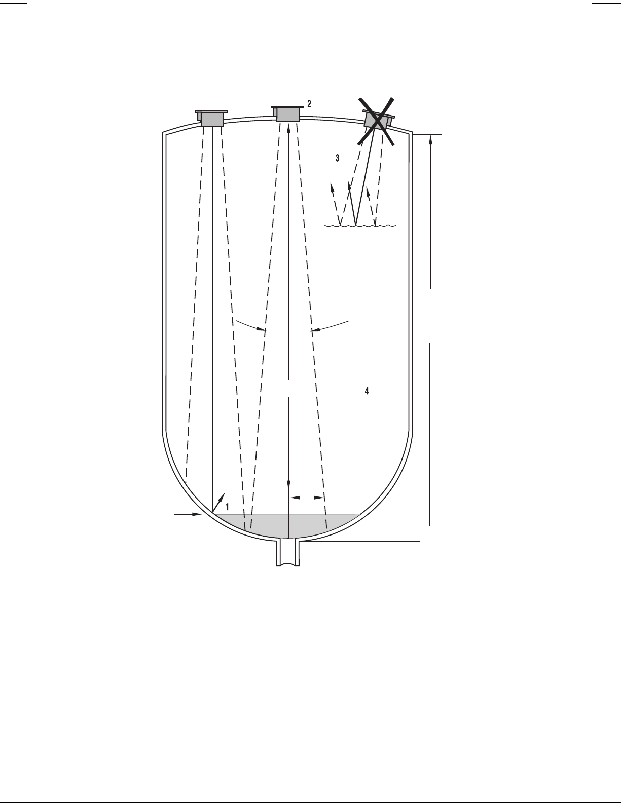
Maximum power is radiated axially (perpendicular)
from the transducer face in a line referred to as the
axis of transmission. Where power is reduced by half
(– 3 dB), a conical boundary defining the sound beam,
centered about the axis of transmission is established.
The diametric measurement of the cone in degrees
defines the beam angle. Impedance matching
techniques are used to optimize the transfer of
power from the transducer into air and from the air
back into the transducer.
SPECIFICATIONS
Model : » ST-100
Measurement range : » typically 30 m (100 ft.) restricted to transceiver maximum▲
Temperature range : » – 40 to 93 °C (– 40 to 200 °F)✧
Frequency : » typically 44 KHz, transceiver dependent
Beam angle : » 7°
Weight* : » 15.9 Kg (35 lb)
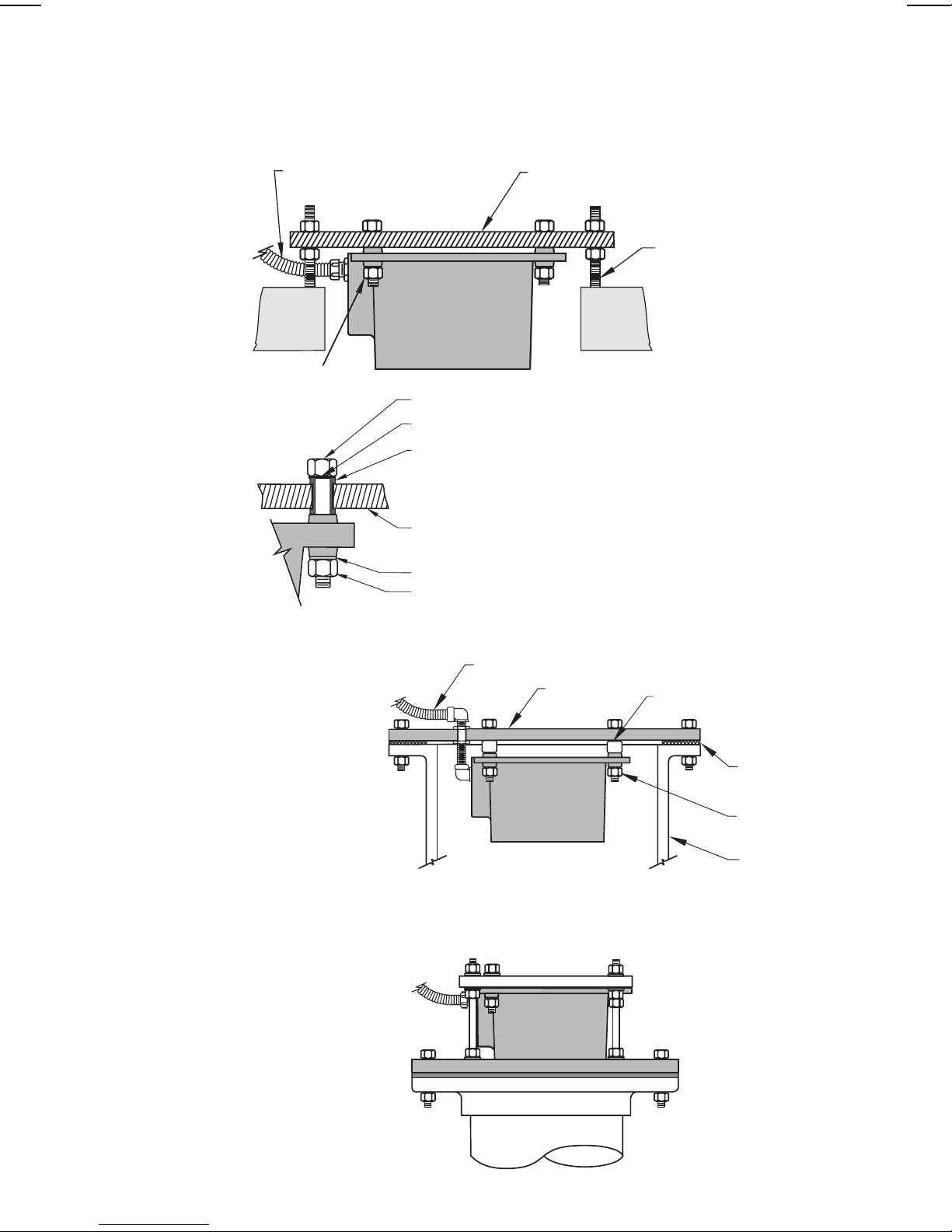
Construction : » aluminum housing with polyurethane face
» 1/2" NPT female conduit connection
» options: » flanging: the transducer can be factory flanged,
consult Milltronics
» facing: » CPVC for corrosive applications.
» Teflonfor corrosive applications.
» polyethylene foam for dry-dust applications.
Separation : » typically 365 m (1200 ft) from associated transceiver▲
Approvals : » CSA, FM and BASEEFA / CENELEC
*approximate shipping weight of transducer with standard cable length and unflanged
▲refer to associated transceiver manual.
✧ maximum temperature for polyethylene foam facing is 77 °C (170 °F).
Teflonis a registered trade mark of Dupont.
–3 db
boundary
transducer
face
axis of
transmission,
perpendicular
to transmission
face
12 °
beam
angle
transducer
PL-419 1

OUTLINE AND CONNECTION
DO’S AND DON’TS
VERY IMPORTANT
Do not route cable openly in raceways.
For optimum isolation against electrical noise, run cable in a grounded metal conduit with no
other cabling (except temperature sensor). Ground shield only at transceiver. Insulate shield
at junctions to prevent inadvertent grounding.
Transducer wiring must be done in conjunction with approved conduit, boxes and fittings
and to procedures in accordance with all governing regulations.
Seal all thread connections to prevent ingress of moisture.
Do not run cable near high voltage or current runs, contactors and SCR control drives.
For BASEEFA Zone 0, cable must be terminated externally to Zone 0 in an appropriate
manner. the cable must be protected against mechanical damage, and arrangements sealed
to prevent migration of atmosphere from Zone 0.
To reduce risk of electrostatic discharge, housing (except face) must be covered with copper
mesh and grounded.
95/07/11
152 mm
(6.0")
284 mm
(11.2")
229 mm
(9.0")
mounting holes
13 mm (0.5") dia.
(3 places)
radiating face
1/2" NPT
internal
thread
23 mm
(0.9")
102 mm
(4.0")
51mm
(2.0")
S
H
L
D
H
O
T
terminal block
in junction box
red (hot)
black
transducer cable
green
shield to approved
ground of junction
box and conduit
shield
hot
RG62 A/U cable
Milltronics
transceiver
PL-419 2

MOUNTING
DO’S AND DON’TS
VERY IMPORTANT
Mount the transducer so that it is above the maximum material level by at least the blanking
value. Refer to the associated transceiver manual.
Do not overtighten mounting. Hand tightening of the mounting hardware is sufficient.
On liquid applications, the transducer must be mounted so that the axis of transmission is
perpendicular to the liquid surface. Avoid aiming into vortexes.
Where the transducer is mounted to a standpipe, the inner standpipe surface and end must be
smooth and free of burrs, ridges and seams.
Consider the optional temperature sensor when mounting the transducer.
PL-419 3

MOUNTING
Typical Solids Application
Typical Liquid Applications
mounting plate
to junction box
refer to mounting detail
threaded studs provide
adjustment for sighting
transducer
Mounting Detail
bolt
washer
rubber washers or
grommet
mounting plate or
blind flange
washer
nut
Blind Flange
Flanged
conduit
connection
blind flange spacer
gasket
nut and bolt
assembly
standpipe
Flange, gasket and
hardware supplied by
customer. Refer to Liquid
Applications - Standpipes
Customer flanged
standpipe. If a metal
flange must be welded to
pipe, refer to Liquid
Applications - Standpipes.
PL-419 4

APPLICATIONS
LIQUID APPLICATIONS - STANDPIPES
In many applications access must be made via a standpipe. In such cases, Milltronics can
provide flange mounted transducers that will readily mate to the flanged standpipe. Another
option is to hang the transducer from a blind flange.
The standpipe length should be as short and the diameter as large as possible. As a rule of
thumb, the –3 dB cone of the sound beam should not intersect the standpipe wall in
applications opening into a vessel or larger area. Otherwise, additional blanking will be
required to compensate for the interference zone created by the opening.
no additional
blanking
required
flanged
transducer
no
intersection
vessel
no vessel
no additional
blanking
required
standpipe
sound beam
intersects
reflection at
interference
zone created
by opening
near blanking extension
of 150 mm (6’) past end of
standpipe may be required
vessel
PL-419 5

LIQUID APPLICATIONS - VOLUME
1. Beam should not detect bin bottom. If this occurs use range extension parameters
(on transceivers where available) to omit false echoes. A 7°beam angle represents a
rise : run of about 15 : 1. In most tanks, the transducer should be centered as much as
possible (without interference from inlet) for optimum reading range.
2. Sound beam must be perpendicular to liquid surface.
If standpipe is used, refer to Liquid Applications - Standpipes.
3. Echo has missed improperly leveled transducer.
4. When performing an empty or full calibration, the tank must contain its normal vapour and
be at its normal temperature.
tank manufacturer’s
empty level
discharge
run
empty level for
"alternate" location.
Below this level, echo
would reflect away
from the transducer.
rise
span: corresponds to
tank manufacturer’s
empty level
7°beam angle
tank manufacturer’s
full level
"Bad"
"Preferred"
"Alternate"
PL-419 6

SOLIDS APPLICATIONS - TYPICAL
bin wall seams
filling profile
emptying profile
1. Transducer angled to avoid seams
in bin wall and aimed at discharge in
order to read bin when empty.
2. Avoid intersecting bin wall seams,
structural members and wall
irregularities. Otherwise, refer to
transceiver manual.
3. Transducer too close to
material inlet. Falling
material will intersect
sound beam and cause
erroneous readings or
loss of echo.
minimal angle of
repose
transducer
discharge
4. On fluid-like solids, aim
transducer perpendicular
to material surface.
5. On dual discharge bins,
aim each transducer at
the discharge point.
PL-419 7

APPLICATIONS WITH AGITATOR
STORAGE BIN WITH AGITATOR
1. Transducer should be kept away from infeed.
2. Where agitators are in use, use the Agitator Discrimination parameter on
transceivers where available.
3. Transducer should be aimed away from wall projections.
infeed
agitator
PL-419 8
Table of contents
Other Milltronics Transducer manuals

Milltronics
Milltronics XPS-10 User manual

Milltronics
Milltronics PL-590 User manual

Milltronics
Milltronics PL-551 User manual

Milltronics
Milltronics XRS-5 User manual

Milltronics
Milltronics EASY AIMER 2 User manual

Milltronics
Milltronics PL-521 User manual

Milltronics
Milltronics ST-50 Series User manual

Milltronics
Milltronics XLS Series User manual
Popular Transducer manuals by other brands

Norcross
Norcross 8000.06T Installation and operation manual

Setra Systems
Setra Systems Multi-Sense 231 manual

Applied
Applied DRDL operating instructions

controlair
controlair 500-BD Installation, operation and maintenance instructions

Schertler
Schertler DYN-V user guide

Setra Systems
Setra Systems Multi-Sense 231RS manual