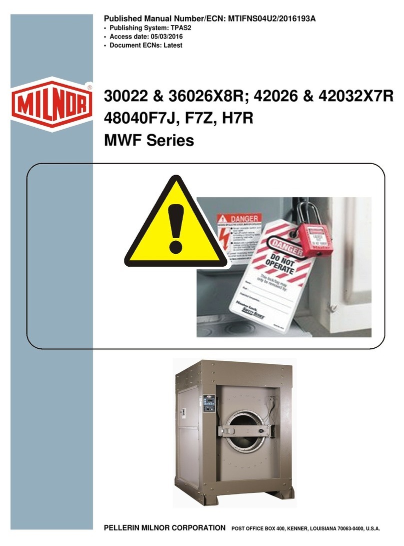
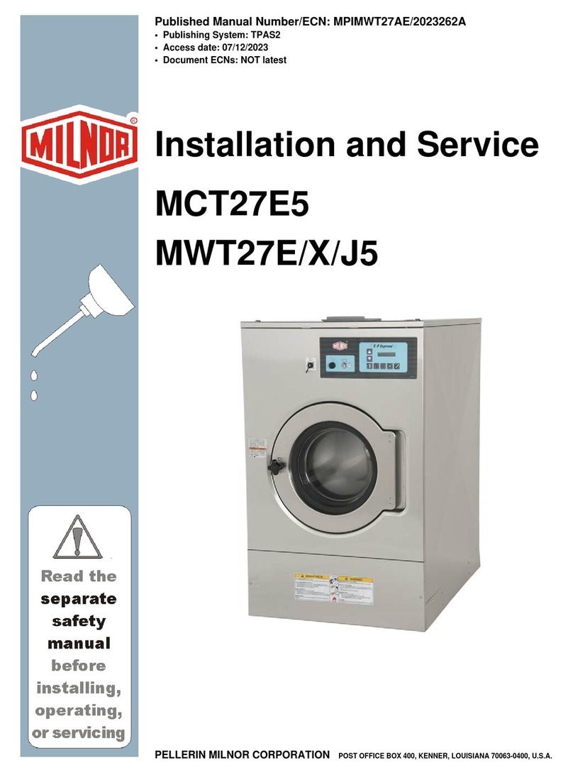
Milnor 30022X8R Operating manual

Published Manual Number/ECN: MKWXAH01U1/2022035A
• Publishing System: TPAS2
• Access date: 01/13/2022
• Document ECNs: Latest
30022X8R
PELLERIN MILNOR CORPORATION POST OFFICE BOX 400, KENNER, LOUISIANA 70063-0400, U.S.A.


MKWXAH01U1/22035A
1. English
Maintenance Guide - Washer-extractor, Top-suspended, Oil
Bearings and Grease Seals, 30022X8R MKWXAH01EN/2021444


English 1


PELLERIN MILNOR CORPORATION Post Office Box 400, Kenner, Louisiana 70063–0400, U.S.A.
Manual Number: MKWXAH01EN
Edition (ECN): 2021444
Maintenance Guide
Washer-extractor, Top-
suspended, Oil Bearings
and Grease Seals, 30022X8R

Pellerin Milnor Corporation i
Contents
1 Machine Description and Identification ........................................................................................4
1.1 About This Manual and Your Milnor® Machine ..............................................................4
1.1.1 Description ..............................................................................................................4
1.1.2 Machine Identification.............................................................................................4
• Machine Data Plate ...............................................................................................4
2 Safety.............................................................................................................................................5
2.1 Safety — Suspended Washer Extractors ...........................................................................5
2.1.1 Safety Alert Messages—Internal Electrical and Mechanical Hazards....................5
2.1.2 Safety Alert Messages—Cylinder and Processing Hazards....................................5
2.1.3 Safety Alert Messages—Unsafe Conditions ...........................................................7
2.1.3.1 Damage and Malfunction Hazards ...............................................................7
2.1.3.1.1 Hazards Resulting from Inoperative Safety Devices.........................7
2.1.3.1.2 Hazards Resulting from Damaged Mechanical Devices ...................7
2.1.3.2 Careless Use Hazards ...................................................................................8
2.1.3.2.1 Careless Operation Hazards—Vital Information for Operator
Personnel (see also operator hazards throughout manual) ...............8
2.1.3.2.2 Careless Servicing Hazards—Vital Information for Service
Personnel (see also service hazards throughout manuals)................8
2.2 Prevent Damage from Chemical Supplies and Chemical Systems ...................................9
2.2.1 How Chemical Supplies Can Cause Damage..........................................................9
• Dangerous Chemical Supplies and Wash Formulas..............................................9
• Incorrect Configuration or Connection of Equipment ........................................10
2.2.2 Equipment and Procedures That Can Prevent Damage.........................................12
• Use the chemical manifold supplied. ..................................................................12
• Close the line.......................................................................................................13
• Do not let a vacuum occur...................................................................................13
• Flush the chemical tube with water.....................................................................13
• Put the chemical tube fully below the inlet.........................................................13
• Prevent leaks. ......................................................................................................13
3 Routine Maintenance...................................................................................................................14
3.1 Routine Maintenance .......................................................................................................14
3.1.1 Maintenance Summary..........................................................................................14
3.1.1.1 Guards and Related Components ...............................................................15
3.1.1.2 Filters, Screens, and Sensitive Components...............................................15
3.1.1.3 Fluid Containers .........................................................................................16
3.1.1.4 Components that Become Worn .................................................................16
3.1.1.5 Bearings and Bushings ...............................................................................16
3.1.1.6 Motor Grease Schedule ..............................................................................16
3.1.1.7 Mechanisms and Settings ...........................................................................17
3.1.2 How To Remove Contamination ...........................................................................17
3.1.3 Lubricant Identification .........................................................................................18
3.1.4 Grease Gun Procedures .........................................................................................19
3.1.5 Procedures for Bearing Components Connected to a Grease Plate.......................19
3.1.6 Procedures for Motors ...........................................................................................20
3.1.7 How To Show the Maintenance On a Calendar ....................................................22
3.2 Maintenance Components—Machines and Controls Group ...........................................23
ii Pellerin Milnor Corporation
3.2.1 How to Examine V-belts and Pulleys ....................................................................23
3.2.2 Inverters.................................................................................................................25
3.2.3 Chemical Devices..................................................................................................25
3.2.4 Water and Steam Devices ......................................................................................26
3.2.5 How to Examine Compressed Air Mechanisms....................................................28
3.2.6 How to Do a Test of Emergency Stop Mechanisms..............................................30
3.3 Maintenance Components—Large Extractors ................................................................32
3.3.1 Lubricant Maintenance for Oil-filled Bearing Housings.......................................32
3.3.2 About the Shock Absorbers...................................................................................32
Figures
Figure 1 Machine Data Plate.....................................................................................................4
Figure 2 Incorrect Configurations That Let the Chemical Supply Go In the Ma-
chine by a Siphon......................................................................................................11
Figure 3 Incorrect Configurations That Let the Chemical Supply Go In the Ma-
chine by Gravity........................................................................................................12
Figure 4 Examples of Manifolds for Chemical Tubes. Your equipment can look
different.....................................................................................................................12
Figure 5 A Configuration that Prevents Flow in the Machine When the Pump is
Off (if the chemical tube and tank have no pressure) ...............................................13
Figure 6 Motor Grease Maintenance Conditions ....................................................................21
Figure 7 Belt and Pulley Conditions To Look For .................................................................23
Figure 8 How to Adjust Belt Tension On a Machine That Uses Spring Tension ...................24
Figure 9 Electric Box and Inverter. These are examples. Your machine can look
different.....................................................................................................................25
Figure 10 Chemical Inlet Manifolds for Chemical Pump Systems. See caution
statement below. These are examples. Your machine can look different. ................26
Figure 11 Soap Chute and Optional 5-compartment Supply Injector. These are ex-
amples. Your machine can look different. ................................................................26
Figure 12 Air Tube for the Water Level Sensor. These are examples. Your ma-
chine can look different. ...........................................................................................27
Figure 13 Water Pressure Regulator for Chemical Flush. These are examples.
Your machine can look different...............................................................................27
Figure 14 Steam Inlet Strainer. These are examples. Your machine can look
different.....................................................................................................................28
Figure 15 Compressed Air Inlet Strainers. These are examples. Your machine can
look different.............................................................................................................28
Figure 16 Self-purging Air Line Filter to Remove Moisture and Other Contamina-
tion. These are examples. Your machine can look different.....................................29
Figure 17 Compressed Air Mechanisms These are examples. Your machine can
look different. ...........................................................................................................30
Figure 18 Oil Maintenance Areas for Bearing Assembly. A 30022T5E is shown.
Your machine can look different...............................................................................32
Figure 19 Grease Ports for Oil-filled Bearing Assembly with Seal Grease
Maintenance..............................................................................................................32
Figure 20 Suspension Components on Each Side of Rubber Spring-Hung Washer-
extractors...................................................................................................................33
Contents

Pellerin Milnor Corporation iii
Tables
Table 1 Guards and Related Components .............................................................................15
Table 2 Filters, Screens, and Sensitive Components ............................................................15
Table 3 Fluid Containers .......................................................................................................16
Table 4 Components that Become Worn ..............................................................................16
Table 5 Bearings and Bushings .............................................................................................16
Table 6 Motor Grease Schedule ............................................................................................17
Table 7 Mechanisms and Settings .........................................................................................17
Table 8 Contamination Types, Cleaning Agents, and Procedures ........................................17
Table 9 Lubricant Identification ...........................................................................................19
Table 10 Motor Grease Intervals and Quantities ....................................................................22
Table 11 Where to Put Marks On a Calendar .........................................................................23
Contents

4Pellerin Milnor Corporation
1 Machine Description and Identification
BNUUUF02 / 2021442 BNUUUF02 0000369288 10/25/21 9:27 AM Released
1.1 About This Manual and Your Milnor® Machine
BNUUUF02.C01 0000369287 A.6 A.9 10/14/21 8:55 AM Released
This manual applies to two or more models that share the mechanical characteristics stated below.
If you received this manual with your machine, your machine is one of the applicable models.
However, before using this manual, verify that your machine does have these characteristics.
1.1.1 Description
BNUUUF02.C02 0000369286 A.6 A.35 11/16/21 8:39 AM Released
Washer-extractors wash linen using water and non-volatile chemicals then remove excess water
by centrifugal force. This washer-extractor is the mechanical type described below.
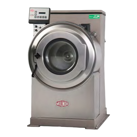
30022X8R A machine represented by this model number is a top suspended (rubber springs)
washer-extractor with an oil-filled bearing housing and grease seals. The capacity is 60 lb.(27
kg).
1.1.2 Machine Identification BNUUUF02.R01 0000369284 A.6 A.9 10/25/21 9:22 AM Released
Machine Data Plate — Find the model number and other data for your machine on the ma-
chine data plate affixed to the machine and described below.
Figure 1. Machine Data Plate
View of Data Plate (English text shown) Legend
1. Model number.
2. Data that uniquely identifies your
machine
3. Cylinder maximum rotation speed
in revolutions per minute, if
applicable
4. Cylinder volume in the units of
measure shown, if applicable
5. Piped utility requirements
6. Hydraulic oil pressure, if
applicable
7. Electrical requirements
8. Part number for multi-unit ma-
chine, if applicable.

2 Safety
BNWSUS08 / 21224 BNWSUS08 0000348933 A.2 5/26/21 12:00 PM Released
2.1 Safety — Suspended Washer Extractors
BNWSUS08.C01 0000348932 A.6 A.2 5/26/21 11:48 AM Released
2.1.1 Safety Alert Messages—Internal Electrical and
Mechanical Hazards BNWSUS01.C03 0000234965 A.6 A.2 A.4 1/2/20 2:19 PM Released
The following are instructions about hazards inside the machine and in electrical enclosures.
WARNING: Electrocution and Electrical Burn Hazards — Contact with electric
power can kill or seriously injure you. Electric power is present inside the
cabinetry unless the main machine power disconnect is off.
�Do not unlock or open electric box doors.
�Do not remove guards, covers, or panels.
�Do not reach into the machine housing or frame.
�Keep yourself and others off of machine.
�Know the location of the main machine disconnect and use it in an emergency to re-
move all electric power from the machine.
WARNING: Entangle and Crush Hazards — Contact with moving components nor-
mally isolated by guards, covers, and panels, can entangle and crush your
limbs. These components move automatically.
�Do not remove guards, covers, or panels.
�Do not reach into the machine housing or frame.
�Keep yourself and others off of machine.
�Know the location of all emergency stop switches, pull cords, and/or kick plates and
use them in an emergency to stop machine motion.
2.1.2 Safety Alert Messages—Cylinder and Processing
Hazards BNWSUS03.C03 0000234973 A.6 A.2 A.3 1/2/20 2:19 PM Released
The following are instructions about hazards related to the cylinder and laundering process.
Pellerin Milnor Corporation 5

6Pellerin Milnor Corporation
DANGER: Entangle and Sever Hazards — Contact with goods being processed can
cause the goods to wrap around your body or limbs and dismember you.
The goods are normally isolated by the locked cylinder door.
�Do not attempt to open the door or reach into the cylinder until the cyl-
inder is stopped.
�Do not touch goods inside or hanging partially outside the turning
cylinder.
�Do not operate the machine with a malfunctioning door interlock.
�Open pocket machines only—Do not jog the cylinder and pull the goods at the same
time.
�Open pocket machines only—Keep yourself and others clear of cylinder and goods
during jogging operation.
�Do not operate the machine with malfunctioning two-hand manual controls.
�Know the location of all emergency stop switches, pull cords, and/or kick plates and
use them in an emergency to stop machine motion.
�Know the location of the main machine disconnect and use it in an emergency to re-
move all electric power from the machine.
WARNING: Crush Hazards — Contact with the turning cylinder can crush your limbs.
The cylinder will repel any object you try to stop it with, possibly causing
the object to strike or stab you. The turning cylinder is normally isolated
by the locked cylinder door.
�Do not attempt to open the door or reach into the cylinder until the cyl-
inder is stopped.
�Do not place any object in the turning cylinder.
�Do not operate the machine with a malfunctioning door interlock.
�Open pocket machines only—Keep yourself and others clear of cylinder and goods
during jogging operation.
�Do not operate the machine with malfunctioning two-hand manual controls.
WARNING: Confined Space Hazards — Confinement in the cylinder can kill or injure
you. Hazards include but are not limited to panic, burns, poisoning, suffo-
cation, heat prostration, biological contamination, electrocution, and
crushing.
�Do not attempt unauthorized servicing, repairs, or modification.
WARNING: Explosion and Fire Hazards — Flammable substances can explode or
ignite in the cylinder, drain trough, or sewer. The machine is designed for
washing with water, not any other solvent. Processing can cause solvent-
containing goods to give off flammable vapors.
�Do not use flammable solvents in processing.
Safety

Pellerin Milnor Corporation 7
�Do not process goods containing flammable substances. Consult with your local fire
department/public safety office and all insurance providers.
2.1.3 Safety Alert Messages—Unsafe Conditions
BNWSUS04.C01 0000235002 A.6 A.2 A.3 12/10/20 4:36 PM Released
2.1.3.1 Damage and Malfunction Hazards
BNWSUS04.C02 0000235001 A.6 A.2 A.3 12/10/20 4:36 PM Released
2.1.3.1.1 Hazards Resulting from Inoperative Safety Devices
BNWSUS04.C03 0000235000 A.6 A.2 12/10/20 4:36 PM Released
DANGER: Entangle and Sever Hazards — Cylinder door interlock—Operating the
machine with a malfunctioning door interlock can permit opening the door
when the cylinder is turning and/or starting the cycle with the door open,
exposing the turning cylinder.
�Do not operate the machine with any evidence of damage or
malfunction.
WARNING: Multiple Hazards — Operating the machine with an inoperative safety
device can kill or injure personnel, damage or destroy the machine, dam-
age property, and/or void the warranty.
�Do not tamper with or disable any safety device or operate the machine with a mal-
functioning safety device. Request authorized service.
WARNING: Electrocution and Electrical Burn Hazards — Electric box doors—Op-
erating the machine with any electric box door unlocked can expose high
voltage conductors inside the box.
�Do not unlock or open electric box doors.
WARNING: Entangle and Crush Hazards — Guards, covers, and panels—Operating
the machine with any guard, cover, or panel removed exposes moving
components.
�Do not remove guards, covers, or panels.
2.1.3.1.2 Hazards Resulting from Damaged Mechanical Devices
BNWSUS04.C04 0000234999 A.6 A.2 A.4 12/10/20 4:36 PM Released
WARNING: Multiple Hazards — Operating a damaged machine can kill or injure per-
sonnel, further damage or destroy the machine, damage property, and/or
void the warranty.
�Do not operate a damaged or malfunctioning machine. Request authorized service.
Safety

8Pellerin Milnor Corporation
WARNING: Explosion Hazards — Cylinder—A damaged cylinder can rip apart dur-
ing extraction, puncturing the shell and discharging metal fragments at
high speed.
�Do not operate the machine with any evidence of damage or
malfunction.
WARNING: Explosion Hazards — Clutch and speed switch (multiple motor ma-
chines)—A damaged clutch or speed switch can permit the low speed mo-
tor to engage during extract. This will over-speed the motor and pulleys
and can cause them to rip apart, discharging metal fragments at high speed.
�Stop the machine immediately if any of these conditions occur: • ab-
normal whining sound during extract • skidding sound as extract ends •
clutches remain engaged or re-engage during extract
2.1.3.2 Careless Use Hazards BNWSUS04.C05 0000234998 A.6 A.2 A.3 12/10/20 4:36 PM Released
2.1.3.2.1 Careless Operation Hazards—Vital Information for Operator Personnel
(see also operator hazards throughout manual)
BNWSUS04.C06 0000234997 A.6 A.2 A.4 12/10/20 4:36 PM Released
WARNING: Multiple Hazards — Careless operator actions can kill or injure person-
nel, damage or destroy the machine, damage property, and/or void the
warranty.
�Do not tamper with or disable any safety device or operate the machine with a mal-
functioning safety device. Request authorized service.
�Do not operate a damaged or malfunctioning machine. Request authorized service.
�Do not attempt unauthorized servicing, repairs, or modification.
�Do not use the machine in any manner contrary to the factory instructions.
�Use the machine only for its customary and intended purpose.
�Understand the consequences of operating manually.
2.1.3.2.2 Careless Servicing Hazards—Vital Information for Service Personnel (see
also service hazards throughout manuals)
BNWSUS04.C07 0000234996 A.6 A.2 A.4 12/10/20 4:36 PM Released
WARNING: Electrocution and Electrical Burn Hazards — Contact with electric
power can kill or seriously injure you. Electric power is present inside the
cabinetry unless the main machine power disconnect is off.
�Do not service the machine unless qualified and authorized. You must
clearly understand the hazards and how to avoid them.
�Abide by the current OSHA lockout/tagout standard when lockout/tag-
out is called for in the service instructions. Outside the USA, abide by the OSHA standard
in the absence of any other overriding standard.
Safety

Pellerin Milnor Corporation 9
WARNING: Entangle and Crush Hazards — Contact with moving components nor-
mally isolated by guards, covers, and panels, can entangle and crush your
limbs. These components move automatically.
�Do not service the machine unless qualified and authorized. You must
clearly understand the hazards and how to avoid them.
�Abide by the current OSHA lockout/tagout standard when lockout/tag-
out is called for in the service instructions. Outside the USA, abide by the OSHA standard
in the absence of any other overriding standard.
WARNING: Confined Space Hazards — Confinement in the cylinder can kill or injure
you. Hazards include but are not limited to panic, burns, poisoning, suffo-
cation, heat prostration, biological contamination, electrocution, and
crushing.
�Do not enter the cylinder until it has been thoroughly purged, flushed,
drained, cooled, and immobilized.
BIWUUI03 / 2019296 BNUUUR02 0000160550 E.3 1/2/20 2:14 PM Released
2.2 Prevent Damage from Chemical Supplies and
Chemical Systems
BNUUUR02.C01 0000160549 A.6 E.3 B.3 1/2/20 2:14 PM Released
All Milnor®washer-extractors and CBW®tunnel washers use stainless steel with the ANSI 304
specification. This material gives good performance when chemical supplies are correctly ap-
plied. If chemical supplies are incorrectly applied, this material can be damaged. The damage can
be very bad and it can occur quickly.
Chemical supply companies usually:
• supply chemical pump systems that put the supplies in the machine,
• connect the chemical pump system to the machine,
• write wash formulas that control the chemical concentrations.
The company that does these procedures must make sure that these procedures do not cause dam-
age. Pellerin Milnor Corporation accepts no responsibility for chemical damage to the ma-
chines it makes or to the goods in a machine.
2.2.1 How Chemical Supplies Can Cause Damage
BNUUUR02.R01 0000160548 A.6 E.3 B.5 10/1/21 11:24 AM Released
Dangerous Chemical Supplies and Wash Formulas — Some examples that
can cause damage are:
• a very high concentration of chlorine bleach,
• a mixture of acid sour and hypo chlorite,
• chemical supplies (examples: chlorine bleach, hydrofluosilicic acid) that stay on the stainless
steel because they are not quickly flushed with water.
Safety

10 Pellerin Milnor Corporation
The book “Textile Laundering Technology” by Charles L. Riggs gives data about correct chemi-
cal supplies and formulas.
Incorrect Configuration or Connection of Equipment — Many chemical
systems:
• do not prevent a vacuum in the chemical tube (for example, with a vacuum breaker) when the
pump is off,
• do not prevent flow (for example, with a valve) where the chemical tube goes in the machine.
Damage will occur if a chemical supply can go in the machine when the chemical system is off.
Some configurations of components can let the chemical supplies go in the machine by a siphon
(Figure 2, page 11). Some can let chemical supplies go in the machine by gravity (Figure 3, page
12).
Safety

12 Pellerin Milnor Corporation
Figure 3. Incorrect Configurations That Let the Chemical Supply Go In the Machine by Gravity
Schematic Views
Legend
P...Pump
T...Chemical tank
D...Chemical tube. Liquid in the gray areas can go in the machine.
2.2.2 Equipment and Procedures That Can Prevent Damage
BNUUUR02.R02 0000160545 A.6 E.3 B.3 1/2/20 2:14 PM Released
Use the chemical manifold supplied. — There is a manifold on the machine to at-
tach chemical tubes from a chemical pump system. The manifold has a source of water to flush
the chemical supplies with water.
Figure 4. Examples of Manifolds for Chemical Tubes. Your equipment can look different.
Safety

Pellerin Milnor Corporation 13
Close the line. — If the pump does not always close the line when it is off, use a shutoff
valve to do this.
Do not let a vacuum occur. — Supply a vacuum breaker in the chemical line that is
higher than the full level of the tank.
Flush the chemical tube with water. — If the liquid that stays in the tube between
the pump and the machine can flow in the machine, flush the tube with water after the pump
stops.
Put the chemical tube fully below the inlet. — It is also necessary that there is no
pressure in the chemical tube or tank when the system is off.
Figure 5. A Configuration that Prevents Flow in the Machine When the Pump is Off (if the chemical
tube and tank have no pressure)
Schematic View Legend
I...Chemical inlet on the machine
L...Chemical tube
P...Pump
T...Chemical tank
Prevent leaks. — When you do maintenance on the chemical pump system:
• Use the correct components.
• Make sure that all connections are the correct fit.
• Make sure that all connections are tight.
Safety
Table of contents
Other Milnor Washer manuals

Milnor
Milnor 48040M7K Manual

Milnor
Milnor MWR12J5 User manual

Milnor
Milnor MCT12E5 Manual

Milnor
Milnor 30015T6X User manual

Milnor
Milnor 30022H7J Installation and operating manual

Milnor
Milnor 30022X8J Manual

Milnor
Milnor 36026X8R User manual

Milnor
Milnor BICWUT01 Operating instructions

Milnor
Milnor 60 Series Operating manual

Milnor
Milnor 30015C4A User manual

Milnor
Milnor 30 Series User manual

Milnor
Milnor 42044SR2 User manual

Milnor
Milnor 76028 G3 CBW Manual

Milnor
Milnor MWF63C Series Operating manual

Milnor
Milnor 60044SR2 Manual

Milnor
Milnor 76028 G3 CBW Manual

Milnor
Milnor 30022F8J Installation and operating manual

Milnor
Milnor MWF63C7 Manual

Milnor
Milnor Mark II User manual

Milnor
Milnor 72044 WP3 User manual