Milton Roy LINC L471 Series User manual

I N S T R U C T I O N M A N U A L
ELECTRIC LEVEL CONTROLS
LINC L471 • L471SC • LV471 • L971
SERIES
Recognized as a
world-class leader in
Electric & Pneumatic
level control switches,
flow indicators,
chemical metering
pumps, and
allied products.

I N S T R U C T I O N M A N U A L
ORDERING INFORMATION
To Order, Call 800.455.LINC
Or FAX your order anytime to
215.293.0498
For the Nearest Authorized
Representative:
By Telephone: 800.455.LINC for
the US & Canada, 215.293.0465
or 215.441.0800 for International
customers
By Fax: 215.293.0498
E-mail:
info@miltonroy.com
Technical Support
By Telephone: 800.455.LINC
By e-mail:
info@miltonroy.com
PP LINC
age 1age 1 LINC MILMILTTONON RROOYY •• 201201 IVYLANDIVYLAND RROOADAD •• IVYLANDIVYLAND PPA,A, 1897418974 •• USAUSA •• TEL.TEL. 215.293.0465215.293.0465 •• FFAXAX 215.293.0498215.293.0498

I N S T R U C T I O N M A N U A L
TABLE OF CONTENTS
Contents –L471, 471SC, LV471, L971 Electric Level Controls .......................... Page
L471 & L471SC Series Ordering Chart ...............................................3-4
Scope Of This Manual .............................................................5
Product Description ...............................................................5
Operation .......................................................................5
Features ........................................................................5
Installation ......................................................................6
Maintenance.....................................................................7
Float and Arm....................................................................7
Relay ..........................................................................7
Switch..........................................................................7
Electric Relays: Installation and Maintenance .......................................... 13
Assembly Drawings & Parts Lists
Figure 1, L471-01, 21 Level Switch ...................................................8
L471-01, 21 Level Switch Parts List...................................................8
Figure 2, L471-02, 03 Level Switch ...................................................9
L471-02, 03 Level Switch Parts List...................................................9
Figure 3, L471-01-04 Level Switch................................................... 10
L471-01-04 Level Switch Parts List .................................................. 10
Figure 4, L471-39, 79 Level Switch .................................................. 11
L471-39, 79 Level Switch Parts List.................................................. 11
Figure 5, L471-69, 89 Level Switch .................................................. 12
L471-69, 89 Level Switch Parts List.................................................. 12
Figure 6, Electric Relay 21593...................................................... 14
Electric Relay 21593 Parts List` ..................................................... 14
Figure 7, L471SC-01, 02 Level Switch................................................ 15
L471SC-01, 02 Level Switch Parts List ............................................... 15
Figure 8, L471SC-03, 04 Level Switch................................................ 16
L471SC-03, 04 Level Switch Parts List ............................................... 16
LV471 & L971 Series Ordering Chart ................................................ 17
Figure 9, LV471-04, LV471-04-04 Level Switch ......................................... 18
LV471-04, LV471-04-04 Level Switch Parts List ........................................ 19
Figure 10, L971-01, L971-01-04 Level Switch ......................................... 20
L971-01, L971-01-04 Level Switch Parts List .......................................... 21
LINC MILTON ROY • 201 IVYLAND ROAD • IVYLAND PA, 18974 • USA • TEL. 215.293.0465 • FAX 215.293.0498 Page 2

LEVEL CONTROL SWITCHES
L I N C - L 4 7 1 & L 4 7 1 S C S E R I E S
The LINC-L471 & L471SC Series:
Electric Level Control Switches
Application:
Operation:
Benefits:
Features:
1
I
II
III
re
1
When a relay assembly is used, Class , Div. 1, is limited to Groups C and D.
Page 3 LINCLINCLINC MILMILMILTTTONONON RRROOOYYY ••• 201201201 IVYLANDIVYLANDIVYLAND RRROOOADADAD ••• IVYLANDIVYLANDIVYLAND PPPA,A,A, 189741897418974 ••• USAUSAUSA ••• TEL.TEL.TEL. 215.293.0465215.293.0465215.293.0465 ••• FFFAXAXAX 215.293.0498215.293.0498215.293.0498

LEVEL CONTROL SWITCHES
L I N C - L 4 7 1 & L 4 7 1 S C S E R I E S
Specifications: L471 & L471SC Series Electric Level Control Switches
Ordering Chart:
2
3
3
4
4
4
4
CSA rated to 1500 psi per single seal rating
( onsult factory for higher ratings)c
5
-N 1
-N 1
-N 1
-N 1
1 I,
2
3 1500 psi maximum. Manual override.
4
5
LINCLINC MILMILTTONON RROOYY •• 201201 IVYLANDIVYLAND RROOADAD •• IVYLANDIVYLAND PPA,A, 1897418974 •• USAUSA •• TEL.TEL. 215.293.0465215.293.0465 •• FFAXAX 215.293.0498215.293.0498 Page 4

I N S T R U C T I O N M A N U A L
PRODUCT DESCRIPTION
Scope Of This Manual:
This manual describes and pro-
vides instructions and parts lists
for the LINC-L471, LINC-
L471SC, LINC-LV471 and
LINC-L971 Series Electric Level
Controls.
Product Description:
Used as a high & low level
control, the L471 & L471SC can
activate alarms, provide a switch
input for control systems, or per-
form a variety of desired electri-
cal switch operations actuated
by a liquid or liquid interface.
Operation:
As the float is moved by vary-
ing liquid height, a magnet is
moved closer to or further away
from a switch enclosure. As the
magnet moves closer, a reed
switch in the enclosure closes.
As the magnet moves further
away, the switch opens. The arm
containing the magnet also acts
as a counterweight for the float.
The float is small and will oper-
ate in liquids with a specific
gravity as low as 0.4. The inter-
face type float will operate with
a specific gravity differential as
low as 0.1. The small float per-
mits an economical installation
in locations where other controls
would be cost prohibitive. With
the optional relay mounted in an
explosion-proof case, the control
of larger electrical loads can be
obtained. The manual override
option allows the operator to
manually move the float arm to
the test switch position.
The SC Series is designed to
eliminate the threaded control
connection in mounting with the
use of a bolted ring per API rec-
ommended practice FIND. The
external cage allows for installa-
tion of the control at any elevation.
Features:
• All wetted parts isolated from the environment. These level
controls are safe even in the event of fire.
• *Certified as explosion proof for Hazardous Locations: Class I,
Div. 1, Groups A, B, C, D; Class II, Div. 1, Groups E, F, G; & Class
III, Div. 1.
• All 316 stainless steel wetted parts provide corrosion resistance.
• Our sealed switch assembly prevents dust, dirt, or moisture from
affecting the level control's operation. Classified "Factory Sealed"
by CSA/NRTL/C.
• Cartridge switch assembly provides easy field replacement and
servicing.
• High or low alarm, normally open or normally closed operation
simply by inverting the level control.
*When arelay assembly is used, Class I, Div. 1, is limited to groups Cand D.
Page 5 LINCLINC MILMILTTONON RROOYY •• 201201 IVYLANDIVYLAND RROOADAD •• IVYLANDIVYLAND PPA,A, 1897418974 •• USAUSA •• TEL.TEL. 215.293.0465215.293.0465 •• FFAXAX 215.293.0498215.293.0498

I N S T R U C T I O N M A N U A L
I N S T A L L A T I O N
Installation:
Before installing the level con-
trol, inspect the unit for any
damage. The float arm must
pivot freely. Thread the level
control into the desired connec-
tion. See Drawing 3 for
Suggested installations. The
float requires a minimum clear-
ance of 1 1/4" from the center
line of the unit for proper opera-
tion. For fail-safe operation as a
high level alarm, the conduit
connection must be positioned
to the highest possible location.
For operation as a low level
alarm, the conduit connection
must be positioned to the lowest
possible location. Wiring con-
nections may now be made. Do
not allow the wiring connections
to pull on the switch assembly.
Caution: Do not exceed switch
ratings.
LINC-L471, LINC-L471SC:
SPST, 100 VA AC with 3 AMP
inrush capability, maximum 250
volts.
Breakdown voltage is 300
volts. Electrical ratings are
given for resistive loads. For
inductive loads, de-rate the
switch rating by 50% and do not
exceed the VA ratings on the
inrush current. If the applied
load is inductive, such as a relay
or coil, then a protective device
should be used to prevent
"inductive kick," which may burn
the switch contacts. The protec-
tive device recommended is
dependent on the voltage used.
For DC operation, a diode simi-
lar to an IN34A should be wired
in parallel with the switch. See
Page 11 wiring schematic. For
AC operation, a Varistor should
be wired in parallel with the
switch.
For SPST Switch Cartridge For SPDT Switch Cartridge
Wiring: Wiring:
White - Common White - Common
Black - Normally Open Black - Normally Closed
Red - Normally Open
LINC MILTON ROY • 201 IVYLAND ROAD • IVYLAND PA, 18974 • USA • TEL. 215.293.0465 • FAX 215.293.0498 Page 6

I N S T R U C T I O N M A N U A L
M A I N T E N A N C E
Maintenance:
The LINC-L471 and LINC-
L471SC Series electric level
controls have been designed to
be as maintenance free as pos-
sible. However, the component
parts are subject to normal wear
and must be inspected and
replaced as necessary.
Inspection and maintenance fre-
quency depend upon the severi-
ty of service conditions.
Instructions are provided in this
section for maintaining the con-
trols as units, i.e., float and float
arm, relay and switch cartridge.
All the maintenance procedures
below assume that the control
has been removed from service.
The switch and relay can be
serviced with the control
installed. The power must be
disconnected before removing
the relay enclosure cover or
opening the conduit fitting.
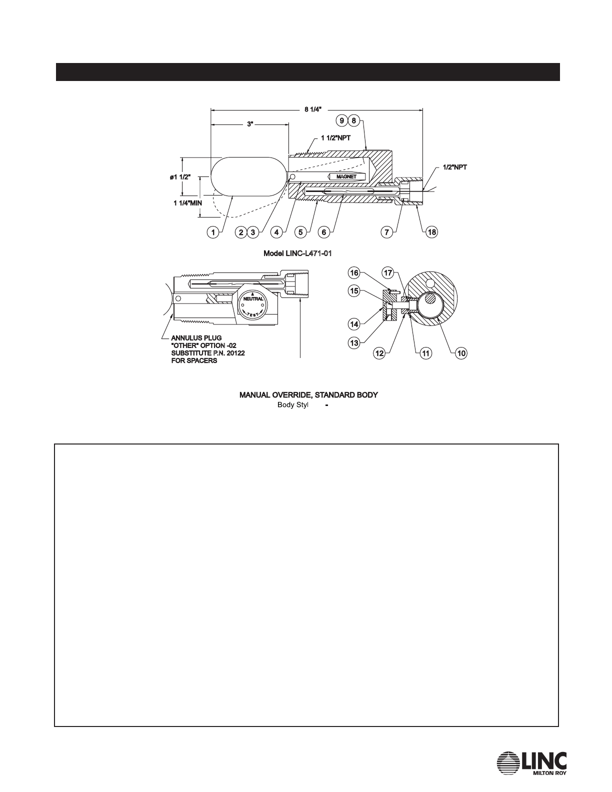
Float and Arm
Check the physical clearance
for float operation. The float
must swing freely. Solvent clean-
ing of the float arm chamber
may be required if used in vis-
cous or dirty liquids. If the float
has collapsed or is perforated,
unscrew the float from the float
arm and replace with a new
float. Use Loctite®to secure the
float to the float arm. To remove
the float arm, drive out the pivot
pin using a 1/8" punch. When
installing the float arm, make
certain that the threaded offset
of the float arm is against the
thick wall of the body.
Relay:
To test for proper relay function,
disconnect the switch leads from
the relay socket. Apply appro-
priate voltage to the coil termi-
nals and observe the relay con-
tact closure with an ohmmeter
connected across the common
and normally closed contacts.
Interrupt the coil power supply
several times while observing
the ohmmeter. No movement
indicates a defective relay, coil
or contacts. This procedure
should be repeated for each set
of contacts in service.
To remove a defective relay, simply
pull the relay from the socket and
replace with a new relay.
When ordering a replacement
relay, be certain to specify coil
voltage. After installing a new
relay, reconnect the switch
leads.
Switch:
To test for switch malfunction,
connect an ohmmeter across
the electrical leads and observe
the meter as the float assembly
is mechanically operated. No
meter movement indicates a
switch failure.
To replace a switch on the
LINC-L471 or LINC-L471SC
Series, pull out the switch car-
tridge along with the grommet
through the conduit adapter.
Slide the new switch cartridge
into the body. Route the switch
wired through the grommet and
seat the grommet in the conduit
adapter.
Page 7 LINCLINC MILMILTTONON RROOYY •• 201201 IVYLANDIVYLAND RROOADAD •• IVYLANDIVYLAND PPA,A, 1897418974 •• USAUSA •• TEL.TEL. 215.293.0465215.293.0465 •• FFAXAX 215.293.0498215.293.0498

I N S T R U C T I O N M A N U A L
LINC-L471-01
Figure 1, LINC L471-01 Level Switch
MANUAL OVERRIDE OPTION MUST
BE INSTALLED WITH CONDUIT
CONNECTION IN 12:00 O’CLOCK POSITION.
The LINC 471-01 & 471-21 Series Parts List.
Model L471-01 L471-21
Item Part # Part # Description Material Qty
1 . . . . . . . . . . 10245......... 10245 ....... Float ............................316 ss ..... 1
2 . . . . . . . . . . 20120......... 20120 ....... Pin..............................316 ss ..... 1
3 . . . . . . . . . . 20121......... 20121 ....... Spacer ..........................316 ss ..... 2
4 . . . . . . . . . . 20853......... 24883 ....... Float Arm Assembly ................316 ss ..... 1
5 . . . . . . . . . . 30313......... 30715 ....... Body ............................316 ss ..... 1
6* .........20495......... 20495 ....... Switch Cartridge ...................304 ss ..... 1
7 . . . . . . . . . . 10087......... 10087 ....... Grommet.........................Nitrile ...... 1
8 . . . . . . . . . . 10012......... 10012 ....... Name Plate .......................316 ss ..... 1
9 . . . . . . . . . . 10324......... 10324 ....... Drive Screw (not shown).............18-8 ss ..... 4
10 . . . . . . . . . . . . . . . . . . . . . . . 24885 ....... Ring Weldment ....................316 ss ..... 1
11 . . . . . . . . . . . . . . . . . . . . . . . 10996 ....... O-Ring ..........................Fluorocarbon 1
12 . . . . . . . . . . . . . . . . . . . . . . . 22271 ....... Packing Gland.....................316 ss ..... 1
13 . . . . . . . . . AIC3214SS ................. Set Screw ........................18-8 ss ..... 1
14 . . . . . . . . . . . . . . . . . . . . . . . 22577 ....... Knob ............................303 ss ..... 1
15 . . . . . . . . . . . . . . . . . . . . . . . 24875 ....... Stem ............................316 ss ..... 1
16 . . . . . . . . . . . . . . . . . . . . . . . 11192 ....... Roll Pin ..........................18-8 ss ..... 3
17 . . . . . . . . . . . . . . . . . . . . . . . 10108 ....... O-Ring ..........................Fluorocarbon 1
18 . . . . . . . . . 20119......... 20119 ....... Conduit Adapter ...................316 ss ..... 1
24836......... 24836 .......
Switch Cartridge SPDT 400
°
F (Optional)
...Sealed ..... 1
*Recommended spare
LINC MILTON ROY • 201 IVYLAND ROAD • IVYLAND PA, 18974 • USA • TEL. 215.293.0465 • FAX 215.293.0498 Page 8

I N S T R U C T I O N M A N U A L
LINC-L471-02 & LINC-L471-03
Figure 2, LINC L471-02 & 03 Level Switch
The LINC 471-02 & 471-03 Series Parts List.
Model L471-02 L471-03
Item Part # Part # Description Material Qty
1 . . . . . . . . . . 20149......... 20136 ....... Float ............................Polypropylene 1
2 . . . . . . . . . . 20120......... 20120 ....... Pin..............................316 ss ..... 1
3 . . . . . . . . . . 20121......... 20121 ....... Spacer ..........................316 ss ..... 2
4 . . . . . . . . . . 20853......... 21671 ....... Float Arm Assembly ................316 ss ..... 1
5 . . . . . . . . . . 30313......... 30313 ....... Body ............................316 ss ..... 1
6* .........20495......... 20495 ....... Switch Cartridge ...................Sealed ..... 1
7 . . . . . . . . . . 10087......... 10087 ....... Grommet.........................Nitrile ...... 1
8 . . . . . . . . . . 20119......... 20119 ....... Conduit Adapter ...................316 ss ..... 1
10 . . . . . . . . . 10324......... 10324 ....... Drive Screw (not shown).............18-8 ss ..... 2
24836......... 24836 ....... Switch Cartridge SPDT 400° F (Optional) Sealed ..... 1
*Recommended spare
Page 9 LINCLINC MILMILTTONON RROOYY •• 201201 IVYLANDIVYLAND RROOADAD •• IVYLANDIVYLAND PPA,A, 1897418974 •• USAUSA •• TEL.TEL. 215.293.0465215.293.0465 •• FFAXAX 215.293.0498215.293.0498

I N S T R U C T I O N M A N U A L
L I N C - L 4 7 1 - 0 1 - 0 4
Figure 3, LINC L471-01-04-N Level Switch
(SUPPLIED WITH
1/2˝ REDUCER BUSHING)
Model LINC L471-01-04-N
The LINC 471-01-04-N Series Parts List.
Model L471-01-04-N
Item Part # Description Material Qty
1 . . . . . . . . . . 10245...................... Float ............................316 ss ..... 1
2 . . . . . . . . . . 20120...................... Pin..............................316 ss ..... 1
3 . . . . . . . . . . 20121...................... Spacer ..........................316 ss ..... 2
4 . . . . . . . . . . 20853...................... Float Arm Assembly ................316 ss ..... 1
5 . . . . . . . . . . 30313...................... Body ............................316 ss ..... 1
6* .........20495...................... Switch Cartridge ...................Sealed ..... 1
7 . . . . . . . . . . 10087...................... Grommet.........................Nitrile ...... 1
8 . . . . . . . . . . 20119...................... Conduit Adapter ...................316 ss ..... 1
9 . . . . . . . . . . 21593...................... Relay Assembly (110 VAC see relays) ............. 1
11 . . . . . . . . . 10324...................... Drive Screw (not shown).............18-8 ss ..... 2
*Recommended spare
LINC MILTON ROY • 201 IVYLAND ROAD • IVYLAND PA, 18974 • USA • TEL. 215.293.0465 • FAX 215.293.0498 Page 10

I N S T R U C T I O N M A N U A L
L I N C - L 4 7 1 - 3 9 & 7 9
Figure 4, LINC L471-39 & 79 Level Switch
The LINC 471-39 & 79 Series Parts List.
Model L471-39 L471-79
Item Part # Part # Description Material Qty
2 . . . . . . . . . . 10324......... 10324 ....... Drive Screw ......................18-8 ss ..... 2
3 . . . . . . . . . . 10087......... 10087 ....... Grommet.........................Nitrile ...... 1
4 . . . . . . . . . . 20119......... 20119 ....... Conduit Adapter ...................316 ss ..... 1
5**.........20495......... 20495 ....... Switch Cartridge ...................Sealed ..... 1
6 . . . . . . . . . . 31079......... 31079 ....... Body ............................316 ss ..... 1
7 . . . . . . . . . . 23540......... 23540 ....... Float/Magnet Arm ..................316 ss ..... 1
8 . . . . . . . . . . 20334......... 20334 ....... Pin..............................316 ss ..... 1
9 . . . . . . . . . . 23604......... 23604 ....... Spacer ..........................316 ss ..... 2
10 . . . . . . . . . 11566...................... Wire Cable .......................304 ss ..... 24”
11 . . . . . . . . . 23503......... 23503 ....... Displacer.........................Polypropylene .1
12 . . . . . . . . . 23500...................... Stop Ring ........................316 ss ..... 1
13 . . . . . . . . . 11565...................... Crimp ...........................18-8 ss ..... 3
14 . . . . . . . . . . . . . . . . . . . . . . . 11571 ....... Pin..............................316 ss .......1
24836......... 24836 ....... Switch Cartridge SPDT 400°F (Optional) . Sealed ..... 1
**Recommended spare
Page 11 LINCLINC MILMILTTONON RROOYY •• 201201 IVYLANDIVYLAND RROOADAD •• IVYLANDIVYLAND PPA,A, 1897418974 •• USAUSA •• TEL.TEL. 215.293.0465215.293.0465 •• FFAXAX 215.293.0498215.293.0498

I N S T R U C T I O N M A N U A L
LINC-L471-69 & 89
Figure 5, LINC L471-69 & 89 Level Switch
MANUAL OVERRIDE OPTION MUST
BE INSTALLED WITH CONDUIT
CONNECTION IN 12:00 O’CLOCK POSITION.
The LINC 471-69 & 89 Series Parts List.
Model L471-69 L471-89
Item Part # Part # Description Material Qty
2 . . . . . . . . . . 10324......... 10324 ....... Drive Screw ......................18-8 ss ..... 4
3 . . . . . . . . . . 10087......... 10087 ....... Grommet.........................Nitrile ...... 1
4 . . . . . . . . . . 20119......... 20119 ....... Conduit Adapter ...................316 ss ..... 1
5* .........20495......... 20495 ....... Switch Cartridge ...................Sealed ..... 1
6 . . . . . . . . . . 31079......... 31265 ....... Body ............................316 ss ..... 1
7 . . . . . . . . . . 24083......... 24083 ....... Float/Magnet Arm ..................316 ss ..... 1
8 . . . . . . . . . . 20334......... 20334 ....... Pin..............................316 ss ..... 1
9 . . . . . . . . . . 23604......... 23604 ....... Spacer ..........................316 ss ..... 1
10 . . . . . . . . . 23503......... 23503 ....... Displacer.........................Polypropylene 1
11 . . . . . . . . . . . . . . . . . . . . . . . 11571 ....... Pin..............................316 ss .......1
12 . . . . . . . . . 24887......... 24887 ....... Ring Weldment ....................316 ss ..... 1
13 . . . . . . . . . 10996......... 10996 ....... O-Ring ..........................Fluorocarbon 1
14 . . . . . . . . . 22271......... 22271 ....... Packing Gland.....................316 ss .......1
15 . . . . . . . . . AIO 3214 ss.... ............ Set Screw ........................18-8 ss ..... 1
16 . . . . . . . . . 22577......... 22577 ....... Knob ............................303 ss ..... 1
17 . . . . . . . . . 24875......... 24875 ....... Stem ............................316 ss ..... 1
18 . . . . . . . . . 11192......... 11192 ....... Roll Pin ..........................18-8 ss ..... 3
19 . . . . . . . . . 10108......... 10108 ....... O-Ring ..........................Fluorocarbon 1
20 . . . . . . . . . 11193......... 11193 ....... Name Plate Manual Check...........304 ss .......1
21 . . . . . . . . . 11566...................... Wire Cable .......................304 ss .....
22 . . . . . . . . . 23500...................... Stop Ring ........................316 ss ..... 2
23 . . . . . . . . . 11565...................... Crimp ...........................18-8 ss ..... 3
24836......... 24836 ....... Switch Cartridge SPDT 400°F (Optional) . Sealed ..... 3
*Recommended spare
LINC MILTON ROY • 201 IVYLAND ROAD • IVYLAND PA, 18974 • USA • TEL. 215.293.0465 • FAX 215.293.0498 Page 12

I N S T R U C T I O N M A N U A L
E L E C T R I C R E L A Y S
Electric Relays
Installation & Maintenance:
•AC Voltage DPDT Plug-In
Type Relay Or DC Voltage
DPDT Plug-In Type Relay:
1. Check the relay coil to
assure it is rated for your
source voltage.
2. Connect one side of the
source to the white wire
within the enclosure
using accepted electrical
practices. Connect the
other side of the source
(black wire) terminal #2.
3. The load may now be
wired to terminals #1, #3,
#4 and #8, #5 and #6.
4. Secure the enclosure
cover prior to applying
source voltage.
5. Apply source voltage.
For use in an SPDT function,
follow the above instructions,
except omit connections for the
load to terminals #8, #5, and #6.
Caution:
On DC applications, the protec-
tive device is directional. If
polarity is reversed, the switch
could be damaged.
(+)
(−)
Page 13 LINCLINC MILMILTTONON RROOYY •• 201201 IVYLANDIVYLAND RROOADAD •• IVYLANDIVYLAND PPA,A, 1897418974 •• USAUSA •• TEL.TEL. 215.293.0465215.293.0465 •• FFAXAX 215.293.0498215.293.0498

I N S T R U C T I O N M A N U A L
E L E C T R I C R E L A Y S
Figure 6, Electric Relay: LINC 21593
1" NPT (P)
CONDUIT CONN.
(SUPPLIED WITH ½"
REDUCER BUSHING)
L21593
Model LINC-21593 115 VAC Plug-In Relay
Item Part # Description Material Qty
1 . . . . . . . . . . 10236...................... Nipple ...........................Galvanized .. 1
2 . . . . . . . . . . L25757 Reducer ............. Bushing..........................Brass ...... 1
3 . . . . . . . . . . 10189...................... Round Head Screw.................Plated...... 1
4 . . . . . . . . . . 12001...................... Terminal ring ......................Insulated ... 1
5 . . . . . . . . . . 20948...................... Mounting Plate ....................Aluminum ... 1
6 . . . . . . . . . . 10472...................... Relay Base .......................Plastic ..... 1
7* .........10688...................... Relay (110 VAC) .............................. 1
8**.........25747...................... Relay Enclosure with Lid ............Plated ...... 1
*Recommended spare
**Dome Cover supplied when Relay is ordered
LINC MILTON ROY • 201 IVYLAND ROAD • IVYLAND PA, 18974 • USA • TEL. 215.293.0465 • FAX 215.293.0498 Page 14

I N S T R U C T I O N M A N U A L
LINC-L471SC-01&LINC-L471SC-02
Figure 7, LINC L471SC-01 & 471SC-02 Level Switch
The LINC 471SC-01, 471SC-02 Series Parts List.
Model L471SC-01 L471SC-02
Item Part # Part # Description Material Qty
1 . . . . . . . . . . 40256......... 40256 ....... Cage ............................Cast Steel .. 1
2 . . . . . . . . . . 10245...................... Float ............................316 ss ..... 2
. . . . . . . . . . . . . . . . . . . . . . . . . 20149 ....... Float ............................Polypropylene 1
3* .........11257......... 11257 ....... Gasket...........................TFE ....... 1
4 . . . . . . . . . . 20334......... 20334 ....... Pin .............................316 ss ..... 1
5 . . . . . . . . . . 20121......... 20121 ....... Spacer ..........................316 ss ..... 2
6 . . . . . . . . . . 10211......... 10211 ....... Cap Screw .......................Plated...... 6
7* .........20495......... 20495 ....... Switch Cartridge ...................Sealed ..... 1
8 . . . . . . . . . . 30282......... 30282 ....... Body ............................316 ss ..... 1
9 . . . . . . . . . . 20119......... 20119 ....... Conduit Adapter ...................316 ss ..... 1
10 . . . . . . . . . 10087......... 10087 ....... Grommet.........................Nitrile........1
11 . . . . . . . . . 30258......... 30258 ....... Ring Flange ......................Steel....... 1
12 . . . . . . . . . 20853......... 20853 ....... Float Arm Assembly ................316 ss ..... 1
14 . . . . . . . . . 10324......... 10324 ....... Drive Screw (not shown).............18-8 ss ..... 2
24836......... 24836 ....... Switch Cartridge SPDT 400°F (Optional) . Sealed ..... 1
*Recommended spare
Page 15 LINCLINC MILMILTTONON RROOYY •• 201201 IVYLANDIVYLAND RROOADAD •• IVYLANDIVYLAND PPA,A, 1897418974 •• USAUSA •• TEL.TEL. 215.293.0465215.293.0465 •• FFAXAX 215.293.0498215.293.0498

I N S T R U C T I O N M A N U A L
LINC-L471SC-03&LINC-L471SC-04
Figure 8, LINC L471SC-03 & 04 Level Switch
(SUPPLIED WITH
1/2” REDUCER
BUSHING)
-N
The LINC 471SC-03 & 04 Series Parts List.
Model L471SC-03 L471SC-04
Item Part # Description Material Qty
1 . . . . . . . . . . 40256......... 40256 ....... Cage ............................Cast Steel .. 1
2 . . . . . . . . . . 10245......... 10245 ....... Float ............................316 ss ..... 1
3* .........11257......... 11257 ....... Gasket...........................TFE ....... 1
4 . . . . . . . . . . 20334......... 20334 ....... Pin..............................316 ss ..... 1
5 . . . . . . . . . . 20121......... 20121 ....... Spacer ..........................316 ss ..... 2
6 . . . . . . . . . . 10211......... 10211 ....... Cap Screw .......................Plated...... 6
7* .........20495......... 20495 ....... Switch Cartridge ...................Sealed ..... 1
8 . . . . . . . . . . 30282......... 30282 ....... Body ............................316 ss ..... 1
9 . . . . . . . . . . 20119......... 20119 ....... Conduit Adapter ...................316 ss ..... 1
10 . . . . . . . . . 10087......... 10087 ....... Grommet.........................Nitrile ...... 1
11 . . . . . . . . . 30258......... 30258 ....... Ring Flange ......................Steel....... 2
12 . . . . . . . . . 10013......... See below.... Name Plate.......................316 ss ..... 1
13 . . . . . . . . . 10324......... See below.... Drive Screw (not shown).............18-8 ss ..... 2
24836......... See below.... Switch Cartridge SPDT 400°F (Optional) . Sealed ..... 1
*Recommended spare
Model L471SC-01-04-N
Item Part # Description Material Qty
12 . . . . . . . . . 20853...................... Float Arm Assembly ................316 ss ..... 1
13 . . . . . . . . . 10013...................... Name Plate .......................316 ss ..... 1
14 . . . . . . . . . 10324...................... Drive Screw (not shown).............18-8 ss ..... 2
15 . . . . . . . . . 21593...................... Relay Assembly (110 VAC see relays) ............. 1
*Recommended spare
LINC MILTON ROY • 201 IVYLAND ROAD • IVYLAND PA, 18974 • USA • TEL. 215.293.0465 • FAX 215.293.0498 Page 16

LEVEL CONTROL SWITCHES
L I N C - L V 4 7 1 & L 9 7 1 S E R I E S
Specifications: LV471 Vertical Series & L971 Extended Body Series Electric Level Control Switches
I
2
IIIII,
Ordering Chart:
1
N
2
N
2
N
2
N
2
'
If no further requirements are desired, omit 'Other' option codes from the part
number.
2
When a relay assembly is used, Class I, Div. 1, is limited to Groups C, and D.
Page 17 LINC MILTON ROY • 201 IVYLAND ROAD • IVYLAND PA, 18974 • USA • TEL. 215.293.0465 • FAX 215.293.0498

I N S T R U C T I O N M A N U A L
LINC-LV471 : VERTICAL
Figure 9, LINC LV471-04, Vertical Level Switch
Product Description:
The LV-471 is used as a high or
low level control to sound
alarms, operate control equip-
ment or perform a variety of
desired electrical functions.
These controls will operate in
any specific gravity of 0.7 or
higher. The standard unit has a
3" O.D. spherical float and is
rated at 250 psi. The standard
float arm is 4" long. Various
floats and float arm lengths are
available to fit your application.
These controls are available
with a normally closed or nor-
mally open switch arrangement.
This unit is installed through a
1-1/2" NPT fitting and the float
is attached with a cotter key
after the body is screwed into
place. Various flanged models
are also available to meet your
specifications.
(SUPPLIED WITH
1/2” REDUCER
BUSHING)
-N
LINC MILTON ROY • 201 IVYLAND ROAD • IVYLAND PA, 18974 • USA • TEL. 215.293.0465 • FAX 215.293.0498 Page 18

I N S T R U C T I O N M A N U A L
LINC-LV471 : VERTICAL
The LINC LV471-04 Normally Closed Parts List.
Model LV471-04 Normally Closed
Item Part # Description Material Qty
1 . . . . . . . . . . 20119...................... Conduit Adapter ...................316 ss ..... 1
2 . . . . . . . . . . 10087...................... Grommet.........................Nitrile ...... 1
3 . . . . . . . . . . 10012...................... Name Plate .......................316 ss ..... 1
4* .........20495...................... Switch Cartridge ...................Sealed ..... 1
5 . . . . . . . . . . 30316...................... Body ............................316 ss ..... 1
6 . . . . . . . . . . 20152...................... Float Arm Retainer .................316 ss ..... 1
7 . . . . . . . . . . 20444...................... Float Arm Assembly ................316 ss ..... 1
8 . . . . . . . . . . 10237...................... Cotter Pin ........................18-8 ss ..... 1
9 . . . . . . . . . . 10250...................... Float ............................316 ss ..... 1
10 . . . . . . . . . 10324...................... Drive Screw (not shown).............18-8 ss ..... 2
24836...................... Switch Cartridge SPDT 400°F (Optional) . Sealed ..... 1
*Recommended spare
Note: For models below, use the same parts as listed above with the following exceptions:
Model LV471-03 Normally Open
Item Part # Description Material Qty
7 . . . . . . . . . . 20446...................... Float Arm Assembly ................316 ss ..... 1
The LINC LV471-04-04 Normally Closed Parts List.
Model LV471-04-04-N Normally Closed
Item Part # Description Material Qty
1 . . . . . . . . . . 21593...................... Relay Assembly (110 VAC see relays) ............. 1
2 . . . . . . . . . . 20119...................... Conduit Adapter ...................316 ss ..... 1
3 . . . . . . . . . . 10419...................... Name Plate .......................316 ss ..... 1
4 . . . . . . . . . . 10087...................... Grommet.........................Nitrile ...... 1
5* .........20495...................... Switch Cartridge ...................Sealed ..... 1
6 . . . . . . . . . . 30316...................... Body ............................316 ss ..... 1
7 . . . . . . . . . . 20152...................... Float Arm Retainer .................316 ss ..... 1
8 . . . . . . . . . . 20444...................... Float Arm Assembly ................316 ss ..... 1
9 . . . . . . . . . . 10237...................... Cotter Pin ........................18-8 ss ..... 1
10 . . . . . . . . . 10250...................... Float ............................316 ss ..... 1
11 . . . . . . . . . 10324...................... Drive Screw (not shown).............18-8 ss ..... 2
24836...................... Switch Cartridge SPDT 400°F (Optional) . Sealed ..... 1
*Recommended spare
Note: For models below, use the same parts as listed above with the following exceptions:
Model LV471-03-04-N Normally Open
Item Part # Description Material Qty
8 . . . . . . . . . . 20446...................... Float Arm Assembly ................316 ss ..... 1
Page 19 LINC MILTON ROY • 201 IVYLAND ROAD • IVYLAND PA, 18974 • USA • TEL. 215.293.0465 • FAX 215.293.0498
This manual suits for next models
23
Table of contents
Popular Switch manuals by other brands

Buster+Punch
Buster+Punch 1G quick start guide

steute
steute RF 96 SW868 Mounting and wiring instructions

Glogic Simplify
Glogic Simplify SANbox2-8c installation guide

TP-Link
TP-Link TL-SG1008D user guide

Alcatel
Alcatel 1850 TSS-320 Technical handbook

ANTAIRA
ANTAIRA LMX-C602G-SFP-V2 Series Quick installation guide