MIMAC MAXIDROP TWIST User manual

MAXIDROP
TWIST –MAXX –EVO
E
N
G
L
I
S
H
USE AND MAINTENANCE MANUAL
S/N:
Date:
Rev.:
R2


USE AND MAINTENANCE MANUAL
1
INDEX
1. INTRODUCTION......................................................................................................................................................5
1.1. OWNERSHIP OF THE MANUAL.......................................................................................................................5
1.2. PURPOSE OF THE MANUAL ...........................................................................................................................5
1.3. VALIDITY OF THE MANUAL.............................................................................................................................5
1.4. SYMBOLISM......................................................................................................................................................5
1.5. IMPORTANCE OF THE MANUAL.....................................................................................................................5
1.6. INTENDED AUDIENCE.....................................................................................................................................5
1.7. PRESERVATION OF THE MANUAL.................................................................................................................5
2. PRELIMINARY INFORMATION...............................................................................................................................6
2.1. MANUFACTURER DETAILS.............................................................................................................................6
2.2. CUSTOMER SERVICE......................................................................................................................................6
2.3. EC STANDARDS COMPLIANCE DECLARATION............................................................................................6
2.4. NORMATIVE REFERENCES............................................................................................................................6
2.5. GUARANTEE.....................................................................................................................................................6
2.6. SOFTWARE OWNERSHIP................................................................................................................................6
2.7. PREPARATION OF THE WORK PLACES........................................................................................................7
2.8. RECEIVING THE MACHINE..............................................................................................................................7
2.8.1. PACKAGING...............................................................................................................................................7
2.8.2. LIFTING AND HANDLING...........................................................................................................................7
2.8.3. UNPACKING...............................................................................................................................................7
2.9. USERS TRAINING.............................................................................................................................................8
2.10. TERMS OF USE..............................................................................................................................................8
2.11. INTENDED USE ..............................................................................................................................................8
2.12. NOISE WARNINGS.........................................................................................................................................9
2.13. CLOTHING.......................................................................................................................................................9
3. SAFETY..................................................................................................................................................................10
3.1. GENERAL INFORMATION..............................................................................................................................10
3.2. DESCRIPTION OF PICTOGRAMS .................................................................................................................10
3.3. DESCRIPTION OF SAFETY DEVICES...........................................................................................................11
3.3.1. FIXED GUARDS........................................................................................................................................11
3.3.2. MOVABLE GUARDS.................................................................................................................................11
3.4. PLACEMENT OF SECURITY DEVICES AND SIGNALS................................................................................11
3.4.1. MAXIDROP TWIST / MAXIDROP TWIST EVO........................................................................................11
3.4.2. MAXIDROP MAXX / MAXIDROP MAXX EVO..........................................................................................12
3.5. RESIDUAL RISKS ...........................................................................................................................................12
4. MACHINE DESCRIPTION .....................................................................................................................................13
4.1. GENERAL DESCRIPTION ..............................................................................................................................13
4.2. IDENTIFICATION.............................................................................................................................................13
4.3. TECHNICAL SPECIFICATIONS......................................................................................................................13
4.3.1. MAXIDROP TWIST / MAXIDROP TWIST EVO........................................................................................13
4.3.2. MAXIDROP MAXX / MAXIDROP MAXX EVO..........................................................................................14

2
www.mimac.com
4.4. MAIN COMPONENTS.....................................................................................................................................15
4.5. EQUIPMENT ...................................................................................................................................................15
4.6. WORKING AREAS..........................................................................................................................................16
4.6.1. MAXIDROP TWIST / MAXIDROP TWIST EVO........................................................................................16
4.6.2. MAXIDROP MAXX / MAXIDROP MAXX EVO..........................................................................................16
4.7. PRODUCTS OVERVIEW ................................................................................................................................17
5. START-UP AND OPERATION CHECKS..............................................................................................................18
5.1. POSITIONING.................................................................................................................................................18
5.2. ELECTRICAL CONNECTION TO POWER SUPPLY AND EARTH................................................................18
5.3. CONTROL DESCRIPTION..............................................................................................................................18
5.3.1. CONTROL PANEL....................................................................................................................................18
5.3.2. MAIN SWITCH..........................................................................................................................................19
5.3.3. TOUCH SCREEN PANEL.........................................................................................................................19
5.4. PRELIMINARY OPERATIONS........................................................................................................................20
5.4.1. INSERTING THE ROLLER TYPE DOSING UNIT....................................................................................20
5.4.2. INSERTING THE PUMP TYPE DOSING UNIT........................................................................................21
5.4.3. INSERTING THE MOULD ........................................................................................................................22
5.4.4. INSERTING AND ADJUSTING THE WIRE CUTTING SYSTEM.............................................................22
5.4.5. INSERTING/REPLACING THE STEEL WIRE..........................................................................................24
5.5. CHECKING THE SAFETY DEVICES..............................................................................................................26
5.5.1. MAXIDROP TWIST / MAXIDROP TWIST EVO........................................................................................26
5.5.2. MAXIDROP MAXX / MAXIDROP MAXX EVO..........................................................................................27
6. MACHINE USE......................................................................................................................................................28
6.1. SELECTING A PROGRAM .............................................................................................................................28
6.2. CREATING/MODIFYING A PROGRAM..........................................................................................................28
6.3. PARAMETERS’ MENU....................................................................................................................................29
6.4. DESCRIPTION OF PRODUCT PARAMETERS..............................................................................................30
6.4.1. DOSAGE PARAMETERS.........................................................................................................................31
6.4.2. NOZZLES ROTATION PARAMETERS....................................................................................................34
6.4.3. WIRE-CUTTING PARAMETERS..............................................................................................................36
6.4.4. TRAY ADVANCE PARAMETERS ............................................................................................................36
6.4.5. LIFTING PARAMETERS...........................................................................................................................38
6.5. COPYING A PROGRAM.................................................................................................................................39
6.6. MODIFYING PARAMETERS DURING OPERATION .....................................................................................39
6.7. PROTECTING PROGRAMS WITH A PASSWORD........................................................................................40
6.8. PROGRAM BACKUP/RESTORE....................................................................................................................41
6.8.1 BACKUP ....................................................................................................................................................41
6.8.2 RESTORE..................................................................................................................................................41
6.9. WARNINGS ON PROGRAMMING..................................................................................................................42
6.10. STARTING PRODUCTION ...........................................................................................................................43
6.10.1. PLACE THE DOUGH IN THE HOPPER.................................................................................................43
6.10.2. PRESSURIZING THE SYSTEM.............................................................................................................43
6.11. KEY TO MANUAL CONTROL ICONS...........................................................................................................44
6.11.1. DOSING CONTROL ICONS...................................................................................................................44
6.11.2. NOZZLES ROTATION CONTROL ICONS.............................................................................................44
6.11.3. WIRE-CUTTING CONTROL ICONS.......................................................................................................45

USE AND MAINTENANCE MANUAL
3
6.11.4. TRAY ADVANCE CONTROL ICONS......................................................................................................45
6.11.5. LIFTING CONTROL ICONS....................................................................................................................46
6.12. MACHINE STOPPING DURING AN EMERGENCY......................................................................................46
7. SETUP AND DIAGNOSIS......................................................................................................................................47
7.1. MACHINE PARAMETERS...............................................................................................................................47
7.1.1. LANGUAGE SETTING..............................................................................................................................47
7.1.2. DESCRIPTION OF THE MACHINE PARAMETERS ................................................................................47
7.2. DIAGNOSTICS SCREEN ................................................................................................................................51
7.2.1. PLC’S INPUTS AND OUTPUTS ...............................................................................................................52
7.2.2. DOSING MOTOR......................................................................................................................................52
7.2.3. CONVEYOR ADVANCE MOTOR.............................................................................................................53
7.2.4. LIFTING MOTOR ......................................................................................................................................54
7.2.5. NOZZLES ROTATION MOTOR................................................................................................................55
7.2.6. WIRE-CUTTING MOTOR..........................................................................................................................56
7.3. ALARMS AND SIGNALS.................................................................................................................................57
7.3.1. TABLE OVERTRAVEL ALARM: RESETTING INSTRUCTIONS..............................................................60
8. CLEANING.............................................................................................................................................................61
8.1. GENERAL INFORMATION..............................................................................................................................61
8.1.1. FOOD HYGIENE REQUIREMENTS.........................................................................................................61
8.1.2. CLEANING OF PARTS WHICH DO NOT COME INTO CONTACT WITH FOOD....................................61
8.1.3. CLEANING OF PARTS WHICH COME INTO CONTACT WITH FOOD...................................................61
8.2. STATIONARY MOULD DISASSEMBLING AND CLEANING..........................................................................62
8.3. ROTARY MOULD DISASSEMBLING AND CLEANING..................................................................................62
8.4. ROLLER TYPE DOSING UNIT DISASSEMBLING AND CLEANING .............................................................63
8.5. PUMP TYPE DOSING UNIT DISASSEMBLING AND CLEANING .................................................................64
9. MAINTENANCE .....................................................................................................................................................65
9.1. GENERAL INFORMATION..............................................................................................................................65
9.2. SUBJECT TO WEAR PARTS..........................................................................................................................65
9.3. STANDARD MAINTENANCE..........................................................................................................................65
9.4. SPECIAL MAINTENANCE...............................................................................................................................65
9.5. MAINTENANCE OF ELECTRICAL AND ELECTRONIC DEVICES................................................................65
9.6. SPARE PARTS REQUEST..............................................................................................................................65
9.7. STORAGE........................................................................................................................................................65
9.8. DISMANTLING AND DISPOSAL.....................................................................................................................66

4
www.mimac.com

USE AND MAINTENANCE MANUAL
5
1. INTRODUCTION
1.1. OWNERSHIP OF THE MANUAL
This manual belongs exclusively to MIMAC ITALIA SRL Unipersonale.
Reproduction, even partial, is forbidden unless authorized by the Manufacturer.
1.2. PURPOSE OF THE MANUAL
The aim of this manual is to provide information necessary for the correct and safe use of the machine and for carrying
out operation as contemplated in the design phase.
1.3. VALIDITY OF THE MANUAL
This manual reflects the machine state of the art at the time it is placed on the market.
The Manufacturer reserves the right to make changes to the machine at any time and without notice.
Any integration sent by the Manufacturer to users must be kept together with the manual and becomes an integral
part of it.
1.4. SYMBOLISM
Useful information
Important communications regarding safety and caution when carrying out operations
Presence of risks and danger for health and safety
DPI use abligation
Notice regarding machine disposal and packaging elimination
1.5. IMPORTANCE OF THE MANUAL
This manual must be read before starting any operation. Good machine operation is guaranteed if all instructions
contained in this manual are applied correctly.
The machine must not be used and no intervention must be carried out on it before having read this manual carefully
and understood all its content.
It is also forbidden to use the machine for purposes other than those indicated, or to neglect operations that are
necessary for safety.
1.6. INTENDED AUDIENCE
•Accident prevention and safety manager
•Operators in charge of transporting the machine
•Operators in charge of connection to the power source
•Operators in charge of testing the machine
•Operators in charge of the training
•Machine operators
•Operators in charge of maintenance
•Operators in charge of machine disposal
1.7. PRESERVATION OF THE MANUAL
The manual must be kept in good condition and in a suitable place that is known to all machine users.
If the manual is lost, deteriorated or if additional copies are necessary, please contact the Manufacturer directly.
The manual must be kept until the machine is disposed of.
If the machine is sold, the manual must be delivered to the new owner together with the EC standards conformity
declaration and all other attachments.

6
www.mimac.com
2. PRELIMINARY INFORMATION
2.1. MANUFACTURER DETAILS
MIMAC ITALIA S.R.L. Unipersonale
Via dell'Industria, 22
36013 Piovene Rocchette (VI)
ITALIA
Tel.: +39 0445 576250
Fax: +39 0445 576112
2.2. CUSTOMER SERVICE
Machine assistance is supplied by the Manufacturer or the authorized Retailer.
Please contact the Manufacturer or the authorized Retailer for any request and refer to the indications printed on the
information plate of the machine.
2.3. EC STANDARDS COMPLIANCE DECLARATION
The machine indicated in the manual is manufactured in compliance withthe relevant Community Directives that were
in force when the machine was placed on the market. As the machine is not included in Annex IV of the 2006/42/EC
Machinery Directive, the Manufacturer has supplied self-certification for placing the “EC” marking according to the
reference directives.
2.4. NORMATIVE REFERENCES
•Machinery Directive 2006/42/EC
•Low Voltage Directive 2014/35/UE
•Electromagnetic Compatibility Directive 2014/30/UE
•UNI EN ISO 12100:2010 - Safety of machinery - General principles for design - Risk assessment and risk
reduction.
•UNI EN ISO 13850:2015 - Safety of machinery - Emergency stop - Principles of design.
•UNI EN 1088:2008 - Safety of machinery - Interlocking devices associated with guards - Principles for design
and selection.
•CEI EN 60204-1 - Safety of machinery. “Electrical equipment of machines”.
•Regulation (CE) N. 1935/2004 of 27 October 2004.
2.5. GUARANTEE
The machine is guaranteed for 12 months. The guarantee only covers those parts that present production faults and
excludes the electric installation and the motors. The indicated period is valid for a machine that works eight hours a
day and must be halved for heavier-duty conditions.
During the guarantee period the Manufacturer shall supply, free of charge, within the minimum technical periods, and
on Ex-Works terms, the parts or items that have evident manufacturing faults, and only under the condition that the
machine was used following the regulations established by the Manufacturer (installation, use, maintenance and
performance limits).
Items not manufactured by MIMAC ITALIA are excluded from the guarantee, for example motors and electrical
apparatus, cylinders and pneumatic components, as well as all material not directly guaranteed by its own
manufacturer. In addition, all parts damaged during the transport, or because of bad and/or incorrect installation or
maintenance, or because of neglect or incorrect use, are not covered by the guarantee.
If the faulty parts are repaired or replaced in the premises of the customer, he willbe charged withthe cost of travelling,
board and lodging and of the working hours of the technicians sent to repair or replace the parts. The hourly cost shall
be quantified according to the Anima (Federation of the Italian Association of Mechanicaland Engineering Industries)
tables in force at the moment of the intervention.
If in the unquestionable opinion of our technicians it is not possible to intervene in the customer’s premises, the
customer shall send the machine on DDP terms to MIMAC ITALIA who, after repairing the faulty part at no charge,
shall return the machine on ex works terms.
When the previously indicated guarantee period has expired, the customer will be also charged with both the cost of
the replaced parts and the cost of the labour.
The guarantee is valid only for the original purchaser; machine replacement is never foreseen.
The guarantee becomes null and void when the machine has been tampered with, or modified and/or repaired by
people who have not been expressly authorized by MIMAC ITALIA.
2.6. SOFTWARE OWNERSHIP
The implemented software, which runs machine operations, belongs to MIMAC ITALIA having its legal head office in
Via dell'Industria, 22 - Piovene Rocchette (VI) - ITALY.
The Customer is licensed to use the software in compliance with the instructions in this manual.

USE AND MAINTENANCE MANUAL
7
The softwarecannot be altered,modified,copied and/or reproducedwithout writtenauthorisationfrom MIMAC ITALIA.
Being the owner of the software used to runits machines, MIMAC ITALIA will not grant the source codesof itssoftware
for anyreason and will persecute anyone or anything that copies, reproduces, decodes or modifiesthe same software.
2.7. PREPARATION OF THE WORK PLACES
Unless otherwise indicated in the contract, the following must be carried out by the Customer:
•preparation of the areas, including any building works and/or piping and conduit that are required;
•the power supply for the machine, in compliance with the laws in force in the user’s country.
The installation area of the machine, being meant for production of oven-baked products, must have:
•openings that allow the bulkiest parts of the machine to pass;
•construction features complying with the current standards;
•an electric system complying with the current standards; special care must be taken with the earthing system
and the main panel, which must have relative protection devices against overloads and short circuits. The
nominal power installed on the machine is indicated on the identification plate.
The complete electric system must be realized and kept periodically under control by professionally trained
technicians who can accompany each intervention with a declaration of conformity to “the rules of the trade”.
2.8. RECEIVING THE MACHINE
The Manufacturer is not liable for any accident, damage or machine fault that may occur if the
indications that follow are not observed.
Make sure no damage occurred during transport and that the packaging is whole. If this is not the case, inform the
shipping agent and write “Accepted with a reservation” on the shipping document.
If any damage is caused during transport, the shipping company must be informed by the Customer, in writing within
8 days from receipt of the goods. Inform the Manufacturer immediately if serious damage has occurred.
Make sure the goods correspond to the items listed in the shipping document. Inform the Manufacturer immediately
if pieces are missing.
2.8.1. PACKAGING
The machine and its accessories can be delivered:
•without packaging, fixed to the loading surface, only protected by an outer film to prevent scratches;
•by container or in palletized wooden crates.
If transported by sea, the machine is inserted inside a sealed wrapping to protect it from atmospheric agents.
2.8.2. LIFTING AND HANDLING
All operations must be carried out by people who have been authorised and under the
supervision of a person in charge.
Operators must wear all the personal protection equipment necessary for the operations to be
carried out safely and must use suitable tools.
Before starting operations, identify and make sure there are no danger points in the movement area, including the
area where the means of transport is positioned and the installation area.
The transport and lifting means must be suitable for the weight to be lifted. Concerning this, read the weights printed
on the packaging and/or indicated in this manual.
Inspect the cables before using them to make sure there is no damage or signs of wear. Do not twist or knot the
cables and follow the Manufacturer’s instructions; these instructions are valid also for chains or belts.
Be careful when positioning the lifting or slinging systems; make sure the load is perfectly balanced before lifting it.
It is forbidden to get onto the load, or to move and/or remain under it while it is being moved.
It is forbidden, for those people who are not involved in transporting and moving, to access the relative areas.
All operators must remain at a safety distance from the packages when they are lifted from the ground to avoid being
hit if they fall.
Do not allow the load to oscillate during lifting.
Lift the machine using a fork-lift, inserting the forks under the lower surface at the barycentre point
Position the machine on a solid and even floor/worktop.
2.8.3. UNPACKING
When installation has been completed, all the packaging material must be disposed of in compliance with the national
regulations in force.
The equipment and material used for lifting should be positioned in a suitable place and stored carefully for possible
machine transfer.

8
www.mimac.com
2.9. USERS TRAINING
The machine was designed and manufactured for professional use. Those who use the machine must be trained in
order to become familiar with:
•all the functions of the control panel;
•all the installed protection guards and safety systems;
•commissioning and putting out of service;
•the possible work cycles;
•the various machine stopping devices, including the emergency stops;
•loading the material to be processed;
•unloading the processed material;
•the contents of this Manual;
•the checks to be carried out periodically;
•all the routine maintenance operations.
Operators must also avoid doing anything on their own initiative; they do not have to carry out any interventions that
are outside their competence and technical knowledge
If something wrong occurs the operators have to:
•intervene immediately and stop the machine, using the emergency push-button;
•immediately inform their supervisor, and request his timely presence.
When the training phase is completed, operators must undergo an evaluation test on their acquired level of
awareness. The training phase and the result of the aptitude test must be documented within the company.
The machine must not be used by people who have not been declared legally suitable for
handling food products.
2.10. TERMS OF USE
Permitted environmental values for good machine operation:
•temperature from +5 °C to +40 °C with an average not exceeding 35 °C for over 24 hours;
•relative humidity between 30% and 95% (without condensation);
•absence of ionising and non-ionising radiation.
The environment around the machine must be kept clean. Remove the plug from the mains before moving the
machine for cleaning.
The workplace lightning must:
•guarantee good visibility at every point;
•not create dangerous reflections;
•allow for the control panel and the emergency push-buttons to be read clearly.
2.11. INTENDED USE
MIMAC ITALIA is not liable for any injury caused to people or damage to things arising from any unauthorised changes
made to the original operation software granted in use to the Customer.
It is forbidden to use the machine in conditions or for purposes other than those indicated in the manual and MIMAC
ITALIA cannot be held responsible for faults or accidents caused by the non-observance of this rule.
Do not use the machine if the safety devices have been tampered with: before starting to work, the operator must
make sure that the safety devices, such as the emergency push-button and the micro-switches connected to the
mobile guards, are working correctly.
Do not hit the safety guards or place weights on them: even though the machine has solid guards, these are not
suitable for holding heavy weights or being hit hard.
Machine must not be used by unskilled users: this manual must be read carefully before starting to work with the
machine.
Do not direct jets of water directly towards the machine, especiallytowards the guards and the electrical and electronic
parts, while washing the machine and the workplace.
The Manufacturer is not liable for damage if one of the following conditions occurs:
•incorrect installation;
•power supply faults;
•failure to comply with the instructions;
•incorrect machine use or machine used by unskilled users;
•using the machine in a manner that is not indicated in national regulations;
•negligent maintenance operations;
•unauthorised modifications or interventions;
•using spare parts that are not original or not specific for the model.

USE AND MAINTENANCE MANUAL
9
To guarantee maximum working reliability, MIMAC ITALIA has accurately chosen the materialsand components used
to produce the apparatus, which was accurately tested before delivery. Good machine performance over time also
depends on correct use and suitable maintenance in line with the instructions given in this manual.
2.12. NOISE WARNINGS
The dropping machine does not exceed an equivalent continuous noise level of 85 dB(A).
Considerations in compliance with Directive 2006/42/CE P.1.7.4.f
No special precaution must be taken by the operator.
The indicated noise level is an emission level and does not necessarily represent a safe working level.
There is a link between the emission and exposure levels, but it cannot be used to determine if special precautions
are necessary. Factors that influence the true level of exposure of the work force include the characteristics of the
working environment, the other sources of noise, etc., for example the number of machines and the other processes
close by. In addition, the permitted exposure level can vary from one country to another. This information allows the
machine user to evaluate the danger and risks in a better manner.
The machine user and the employer must respect laws regarding operator protection against the daily personal
exposure to noise, with the possible use of personalprotection equipment (earmuffs, etc.) according to the total noise
level present in the work area.
2.13. CLOTHING
As far as clothing is concerned, operators must adhere to food production standards that are current in the European
community and/or in their own Country.
In a simple manner, it is obligatory to:
•wear clothing complying with the health regulations (overalls and headgear that cover hair completely);
•wear disposable sterilized gloves;
•wear accident-prevention footwear that is suitable for the movements to be carried out;
•wear disposable masks that cover the mouth and nose.

10
www.mimac.com
3. SAFETY
3.1. GENERAL INFORMATION
The machine was designed to work safely. All commands are given using a touchscreen panel and the push-button
present on the control panel.
The emergency push-button inhibits all machine functions; to reset them release the emergency push-button and
press the re-establishment push-button. No component will start moving before the emergency push-button is
released.
The stability of the whole machine is sufficient to guarantee use in the indicated operating conditions without risks of
overturning, falling or moving unexpectedly.
Do not tamper with or eliminate the safety devices that are installed on the machine.
Periodically check the effectiveness of the safety systems.
Do not damageor eliminate the safety signals that are applied to the machine; if a safety signal is damaged ormissing,
immediately inform the person in charge of company safety and ask for its replacement.
If operators tamper with the safety devices, the Manufacturer is not liable for any resulting injury to people or damage
to things. The operator becomes the only person responsible when facing competent bodies.
If danger arises for people or things, press the emergency push-button.
3.2. DESCRIPTION OF PICTOGRAMS
ATTENTION! Machine moving parts in action
BE CAREFUL to your hands
DO NOT remove safety devices
DO NOT clean, grease or adjust the machine elements
while they are in action
DO NOT clean the machine using water jets
ATTENTION! Hand crush hazard

USE AND MAINTENANCE MANUAL
11
3.3. DESCRIPTION OF SAFETY DEVICES
3.3.1. FIXED GUARDS
They are fixed with screws and can be removed only using the appropriate tools, which must only be used for
maintenance operations; when maintenance is finished the guards must be correctly repositioned.
3.3.2. MOVABLE GUARDS
They are connected to safety micro-switches or photocells meant for cutting in automatically whenever the covers are
opened. The machine can start production again when the movable guards are closed.
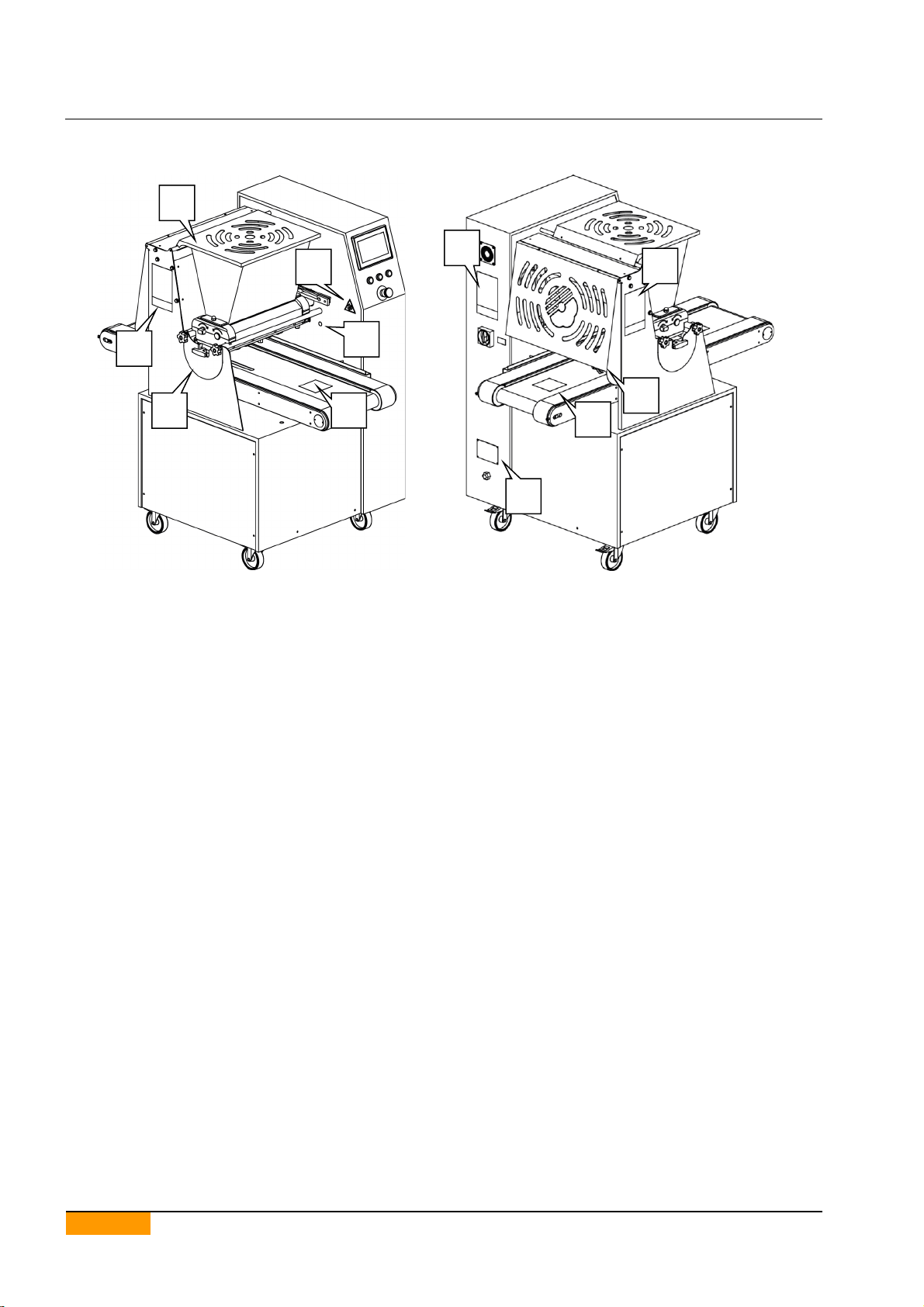
3.4. PLACEMENT OF SECURITY DEVICES AND SIGNALS
3.4.1. MAXIDROP TWIST / MAXIDROP TWIST EVO
1. Hopper movable guard
2. Front guard
3. Photocell
4. Main pictogram
5. Pictogram “Hand crush hazard”
6. Information plate
5
5
3
2
1
5
4
6
3
5
12
www.mimac.com
3.4.2. MAXIDROP MAXX / MAXIDROP MAXX EVO
1. Hopper movable guard
2. Wire-cut device movable guard
3. Front guard
4. Photocell
5. Main pictogram
6. Pictogram “Hand crush hazard”
7. Information plate
3.5. RESIDUAL RISKS
While using the machine for production or maintenance, the residual risks present are possible crushing of the hands
between the die and the conveyor or between the die and the tray positioned above the conveyor.
1
3
7
5
4
2
6
6
5
5
6

USE AND MAINTENANCE MANUAL
13
4. MACHINE DESCRIPTION
4.1. GENERAL DESCRIPTION
Extremely flexible dropping machine for the production of cookies and pastry in general.
Thanks to its interchangeable dosing units and several moulds with nozzles, the dropping machine features great
flexibility in the typology of product and in the choice of the shape.
4.2. IDENTIFICATION
Ineach machine there is an identification plate containing informationabout the Manufacturer and the machine (model
name, serial number, power supply, year of manufacture).
4.3. TECHNICAL SPECIFICATIONS
4.3.1. MAXIDROP TWIST / MAXIDROP TWIST EVO
MAXIDROP TWIST
MAXIDROP TWIST EVO
MAXIDROP TWIST 600
MAXIDROP TWIST 600 EVO
Dimensions
A
B
H
880 mm
1360 mm
1380 mm
1060 mm
1360 mm
1380 mm
Weight
265 kg / 270 kg
285 kg
Hopper capacity
29 lt / 32 lt
43 lt
Power supply
200-240 V - 50/60 Hz - 1ph
Tray size
400x600 mm / 450x660 mm
600x400
600x800
A
B
H

14
www.mimac.com
4.3.2. MAXIDROP MAXX / MAXIDROP MAXX EVO
MAXIDROP MAXX
MAXIDROP MAXX EVO
MAXIDROP MAXX 600
MAXIDROP MAXX 600 EVO
Dimensions
A
B
H
880 mm
1360 mm
1380 mm
1060 mm
1360 mm
1380 mm
Weight
270 kg / 275 kg
290 kg
Hopper capacity
29 lt / 32 lt
43 lt
Power supply
200-240 V - 50/60 Hz - 1ph
Tray dimensions
400x600 mm / 450x660 mm
600x400
600x800
A
B
H

USE AND MAINTENANCE MANUAL
15
4.4. MAIN COMPONENTS
1 - Frame
The frame is made of steel, aluminium alloy and stainless steel, covered by stainless steel panels that are fast and
easy to clean and sanitize.
2 - Conveyor
The conveyor allows the tray to move forwards or backward for an accurate placement and for moving while the
machine is dropping. The conveyor makes also vertical movement to detach the product from the nozzles and to
adjusts the thickness of the products.
3 - Dosing unit
The dosing unit drops the dough put into the hopper. The machine can be equipped with two different type of dosing
unit:
•roller type to handle soft dough (e.g. meringues and éclairs) or harder dough (e.g. shortbread of almond dough);
•pump type to handle fluid dough or semi-dense dough (e.g. sponge cake or cupcake).
4 - Wire-cut device
The wire-cut device allows dosing of harder doughs in the desired thickness. Cutting is achieved by means of a steel
wire fixed to a frame; the latter moves, making the wire rub against the plastic patterns that are placed on the die.
5 - Die
The die, complete with nozzles, gives the wanted shape to the products.
6 - Control panel
The control panel allows the operator to interface with the machine using the buttons and the touch screen control
panel.
4.5. EQUIPMENT
The machine can be provided with different dosing units, moulds and nozzles in accordance with the need of the
customer agreed at the time of the order. The standard equipment includes a kit of service wrenches.
1
2
3
5
6
4

16
www.mimac.com
4.6. WORKING AREAS
4.6.1. MAXIDROP TWIST / MAXIDROP TWIST EVO
Normal running direction
The machine can be used by one operator only, who fills the hopper, feeds the trays and removes them.
1. Hopper filling area
2. Tray feeding area
3. Tray removing area and control panel
4.6.2. MAXIDROP MAXX / MAXIDROP MAXX EVO
Normal running direction
The machine can be used by one operator only, who fills the hopper, feeds the trays and removes them.
1. Hopper filling area
2. Tray feeding area
3. Tray removing area and control panel
1
3
2
1
3
2

USE AND MAINTENANCE MANUAL
17
4.7. PRODUCTS OVERVIEW
The machine can make many types of products set by default. By choosing one of the products available the system
loads specific parameters.
Available products may differ depending on the model and options included.
Fxed product
Long product
Drop shaped product
Fixed product with rotation
Long product with rotation
Donut
Sponge cake
Fixed product with wire-cutting(1)
Long product with wire-cutting(1)
Crown
Continuous pastry(1)
Braid with wire-cutting(1)
Double product with rotation
Drop shaped product with rotation
Multilayer fixed product
Multilayer fixed product with rotation
Multilayer long product
Multilayer long product with rotation
Flame shaped product
Flame shaped product with rotation
Zeppola(2)
(1) Available on MAXIDROP MAXX and MAXIDROP MAXX EVO models only
(2) Available on MAXIDROP TWIST EVO and MAXIDROP MAXX EVO models only

18
www.mimac.com
5. START-UP AND OPERATION CHECKS
5.1. POSITIONING
The floor and/or supports on which the machine is positioned must be suitable for supporting the indicated weights.
Make sure enough space is left around the perimeter of the machine for using and carrying out maintenance on it
safely.
When choosing the machine position, please consider these points:
•the machine size;
•the operator's working areas, the space necessary for loading / unloading the trays and the space necessary for
accessing the control panel;
•the movements necessary for cleaning the work station and the machine;
•the space necessary for carrying out maintenance.
5.2. ELECTRICAL CONNECTION TO POWER SUPPLY AND EARTH
The Customer is always in charge of, and responsible for connecting the machine to the
electric power supply. The Customer is also responsible for power conductor protection and
creating a suitable and reliable earthing system.
The installing electrician must be specialized in work of this type. He/She must also be aware of all the technical
notions and regulations for working in a professional manner.
The machine must be connectedto theelectricpower system of the installation premises incompliance with standards
(IEC-EN6 0204-I,IEC-EN 60349-I).
The power cable must be kept distant from parts that are hot, that can cut, or that move. It must also not obstruct
operator and material movements in the installation area.
Make sure the machine voltage indicated on the identification plate corresponds to the line voltage of the laboratory;
if it does not, DO NOT connect the machine to the power supply, instead contact the Retailer or Manufacturer
immediately.
The machine must be connected to an earthing system which must be prepared by the Customer in compliance with
what is indicated in current standards (LD 547/55 - IEC EN 60204-1 EN60445).
The connecting clamps are prepared inside the electric panel as specified in the attached wiring diagrams. Use the
statutory earthing system, not pipes for gas, water or other unspecified metal holders.
5.3. CONTROL DESCRIPTION
5.3.1. CONTROL PANEL
Operators have the control panel at their disposal, which can be used to carry out operations for setting up and
controlling the machine.
The operator has a stop push-button to stop the machine, in addition to an emergency stop push-button and safety
devices on the safety guards. Press the stop push-button to stop production temporarily. In danger situations, use the
emergency stop push-button to immediately stop the machine.
1
3
2
4
6
5
This manual suits for next models
2
Table of contents


