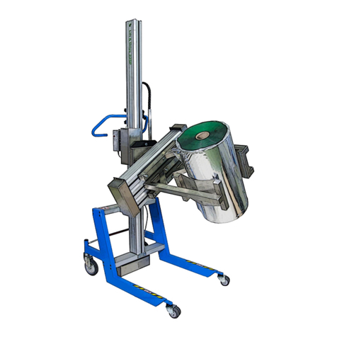
Pronomic 19470 User manual

Complete Turn Device
Model 19470
Also for 19471, 19474, 19475, 19480
User’s manual
Original instructions

It is important that you read and understand this manual before the attachment is used.
Questions? –Contact your supplier or the manufacturer.
Pronomic AB
Visiting address:
Bäckvägen 18
192 54 Sollentuna
Sweden
Postal address:
Box 5504
192 05 Sollentuna
Sweden
R210831

Contents
1Description of the attachment Expand&Turn.....................................................................1
1.1 Warranty...................................................................................................................................... 1
2Assembly............................................................................................................................2
2.1 Mounting the turn plate on the 90/130P trolley ........................................................................ 2
2.2 Mounting the turn plate on the 175/225P trolley ...................................................................... 2
2.3 Disassembly ................................................................................................................................. 3
3Use.....................................................................................................................................3
3.1 Operating instructions................................................................................................................. 3
4Safety.................................................................................................................................3
4.1 Storage and transport ................................................................................................................. 3
5Maintenance......................................................................................................................3
5.1 Every day ..................................................................................................................................... 4
5.2 Every month, or as needed ......................................................................................................... 4
5.3 Sign and decals ............................................................................................................................ 4
5.4 Troubleshooting .......................................................................................................................... 4
6Technical data....................................................................................................................6
6.1 Max torque .................................................................................................................................. 7
6.2 Time for 90 degree turn .............................................................................................................. 7
7Approved attachments for Lift&Drive trolleys....................................................................8
8Drawings ............................................................................................................................9
8.1 Overview...................................................................................................................................... 9
8.2 Dimensions ................................................................................................................................ 10
EC DECLARATION OF CONFORMITY FOR PARTIAL MACHINERY ......................................................... 11

1
1Description of the attachment Turn
The Turn device is ergonomically designed for maximum handling safety. Before using Turn, the
manual must be read and understood in order to guide you to operate the device in a correct and
safe way.
In order to operate the complete device, i. e. the Turn device mounted on the lift-trolley, it is
important to read this manual in combination with the separate manual delivered with the lift-
trolley.
After many years of service, your trolley and turn plate should be discarded in an environmentally
correct way.
1.1 Warranty
The warranty applies for one (1) year from the date of delivery for material- and manufacturing
errors. For the warranty to apply, maintenance should be carried out according to instructions.
This warranty does not cover normal maintenance, settings or regular adjustments. Neither will
labour costs from such measures be covered by the warranty. Damages caused by abuse or
improper use of the equipment will also void the warranty.

2
2Assembly
When mounting the attachment, protective shoes should be worn, as the parts can cause injury if
dropped.
2.1 Mounting the turn plate on the 90/130P trolley
1. Undo the screws in the slide that are provided to hold the end effector. Fit the turn plate
with the screws into the slide of the column.
2. Detach the handlebar of the trolley. Slide the motor control box into the slot in the back of
the column so that it comes above the power pack and tighten the screws. Refit the
handlebar. The cable carrier between the motor control box and the turn plate should now
be on the left-hand side of the column. Plug the power cable of the turn plate to the “power
out” socket of the power pack.
3. Trolleys with an extended column, +300 mm or +500 mm, a steel strip must be mounted on
the column (above the handlebar) to prevent the cable carrier being bent backwards. Fit
this item into the slot in the back of the column and make it tight.
4. When test-running be careful to see that the turn plate module does not foul any part of
the trolley and that the cable carrier is not too short or too long.
2.2 Mounting the turn plate on the 175/225P trolley
1. Undo the screws in the slide that are provided to hold the loading platform. The screws that
come with the trolley cannot be used, since they are too long. Lift the turn plate into place
against the slide and position the accompanying spacer key between the turn plate and the
slide. Tighten the turn plate assembly using the screws that come with the turn plate.
2. Detach the handlebar of the trolley. Slide the motor control box into the slot in the back of
the column so that it comes above the power pack and tighten the screws. Refit the
handlebar. The cable carrier between the motor control box and the turn plate should now
be on the left-hand side of the column. Plug the power cable of the turn plate to the “power
out” socket of the power pack.
3. On the 175P a steel slip must be fitted (above the handlebar) to prevent the cable carrier
being bent backwards. Fit this item into the left-hand slot in the back of the column and
make it tight.
4. When test-running be careful to see that the turn plate module does not foul any part of
the trolley and that the cable carrier is not too short or too long.

3
2.3 Disassembly
To disassemble the turn plate, proceed as in sub-section .1.1 Mounting the turn plate on the
90/130P trolley, but in the reverse order.
3Use
3.1 Operating instructions
The turn plate functions are controlled from the motor control box. The
motor control box functions vary depending of the end effectors used
together with the turn plate. The joystick controls the variable rotation
speed of the turn plate. The turn plate has endless rotation angle.
4Safety
The maximum load must not be exceeded (max-load, se heading 6
Technical specifications). The trolley and the end effectors may not be used for lifting people. The
operator is asked to be aware of the risk of injury that exists when raising or lowering the end
effector. Avoid putting your arm through the handlebar when trying to get hold of or pick up
something from the end effector. The operator must always be aware of not holding his hands or
other parts of his body under a hanging load.
Always lower the end effector to the lowest possible level that the circumstances at ground level
allow for, before any transport of goods is attempted. The load shall always be centered and stand
as close to the column as possible in order to provide maximum stability. Be especially careful
when passing over thresholds, door steps, cables and other
4.1 Storage and transport
When transporting and storing the turn plate attached to a lift-trolley, the power cable between
the lifters power pack and the motor control box must be unplugged.
The trolley is only intended for in-door use and on flat plain ground.
5Maintenance
To ensure that your Turn device will function at its best it is important to give it regular
maintenance as specified below

4
5.1 Every day
Wash off the turn plate with a cleaning agent suitable for Aluminum and stainless steel. Follow
instructions on the bottle or can. Wipe off the turn plate. Do not use high-pressure flushing, which
is liable to damage both the electronics and the chassis
5.2 Every month, or as needed
Check that no abnormal noises have arisen in the motor and gear.
1. Electrical connections: check all connections and deal with any damage or wear. If necessary,
replace with new parts.
2. Screws and nuts: check that all screws and nuts have been made tight.
3. Labels: check that the labels are secure and fully legible. They are there for your safety.
5.3 Sign and decals
Check that the following signs and decals are attached and are fully legible.
Sign/decal
Description
Placement
Unit designation
Decal with serial number
One decal on the control box
and one decal on the
attachment
Instruction decal
Decal instructing the
operator
Front of the control box
5.4 Troubleshooting
The Turn device is designed for safe and effective operation on condition that the routine
maintenance is looked after in accordance with instructions. Should any problem arise, advice on
what to do is to be found in the trouble-shooting list below.
If the problem persists after this, contact a serviceman or Pronomic AB.

5
Symptom
To do
1
Motor does not turn at all
A
Check the battery voltage which should be 24 volt.
B
Make sure the connections with motor are intact.
C
Make sure the connections from the power pack to the motor control box
are intact.
2
The turn plate does not turn, but
the motor works
A
See above under heading Symptom, section 1.
B
Check through the listed tasks in section 2.5 maintenance.
3
The turn plate moves slowly
A
See above under heading Symptom, section 1.
4
The turn plate sounds strange
while turning
A
Check through the listed tasks in section 2.5 Maintenance.

6
6Technical data
The measured square value for vibrations while squeezing does not exceed 2,5 m/s2.
The sound level while rotating does not exceed 70 dB(A).
Material: aluminum and stainless steel, 18/8.
Type:
Complete turn devices 19470-19480
Turn 19400, 19401, 1940
Outer dimensions LxWxH
34x1 16x361
Rotation angle
~
Dimension from floor to rotation center
point:
Lift & Drive 90P/130P
305 mm
Lift & Drive 175/225P
300 mm
Turning speed w/o load
(see diagram)
Max torque
(see diagram)
Max load
220 kg, depending of the maximum
capacity of the lift trolley
Weight of unit
21.5 kg
Intermittence
15% per 10 min, maximum load
Voltage
24 V DC

7
6.1 Max torque
6.2 Time for 90 degree turn
Table on turning speed

8
70E
90E
90IE
90JE
90P
130P
175P
225P
325P+
15012 XXXXXX
15013 XXXXXXXX
15014 XXXXXXXX
15015 XXXXXXXX
15016 XXXXXXXX
15017 XXXXXXXX
15018 X X
15019 XXXXXX
15024 X X
15080 X X
15322 X X
15324 X
15338 X
15370-15372 X
16020 X X
16038 X X X
16338 X
16041-16044 X X
16048-16049 X X
17182 X X
17231 XXXXXX
17241 XXXXXX
17710 XXXXXX
17720 XXXXXX
17730 XXXX
17740 XXXX
17940 X X X
17972 X X
17980 XX
19511 X X
19201 X X
19285 X X
19470 X X
19471 X X
19472 X X
19473 X X
19474 X X
19475 X X
19476 X X
19477 X X
19478 X X
19479 X X
19480 X X
20205A-10 XXXX
20080 XXXXXX
21851-21854 XXXX
220066-220069 XXX
220100 XXX
7Approved attachments for Lift&Drive trolleys
Complete Turn Devices 19470-19480

9
8Drawings
8.1 Overview

10
8.2 Dimensions

11
9EC DECLARATION OF CONFORMITY FOR PARTIAL MACHINERY
ORIGINAL
(in accordance with 2006/42/EC, Annex II 1B)
Manufacturer
Pronomic AB
Box 5504
192 05 Sollentuna
Model
Turn unit 19470/ 19471/ 19474/ 19475/ 19480
Authorized to compile the
technical file
Samuel Pierre, Pronomic AB, BOX 5504, 192 05 Sollentuna, Sweden
Applied directives:
2006/42/EC
Machinery directive
2014/30/EU
EMC directive
Applied standards:
SS-EN ISO 12100:2010
Safety of machinery –General principles for design. Risk assessment and risk
reduction
SS-EN ISO 13854:2019
Safety of machinery - Minimum gaps to avoid crushing of parts of the human body
We hereby declare that the above referenced machine, built and equipped with attachments included in
this manual, is in conformity with stated directives and standards.
Sollentuna, 2021-08-31
…………………………………………………………
Joakim Stannow, PRONOMIC AB

12
………………………………………………………………………………………………………….…………………………………………………
Serial number
…………………………………………………………………………………………
Signature, Inspector
…………………………………………………………………………………………
Place, date
Pronomic AB –SWEDEN
Box 5504
192 05 Sollentuna
Turn Unit
19470
19474
19480
19471
19475

Distributed by:
This manual suits for next models
4
Table of contents
Other Pronomic Industrial Equipment manuals
Popular Industrial Equipment manuals by other brands
Rockwell Automation
Rockwell Automation Allen-Bradley PowerMonitor 5000 Unit user manual
Sulzer
Sulzer XJ Series Assembly and installation instruction

Barco
Barco ISIS LFC installation guide
TECNA
TECNA 9354AX instruction manual
Aventics
Aventics TRB Series Repair instructions
Siemens
Siemens SIRIUS S00 operating instructions
HYDAC International
HYDAC International CS 2000 Series Operating and maintenance instructions
Flonidan
Flonidan Uniflo 1200 GVEC manual
ABB
ABB HT608698 Operation manual
Daikin
Daikin ECORICH EHU 40 Series instruction manual

Traub
Traub TNX65/42 Maintenance Instruction

Eriez
Eriez HD-46 Installation, operation and maintenance instructions
