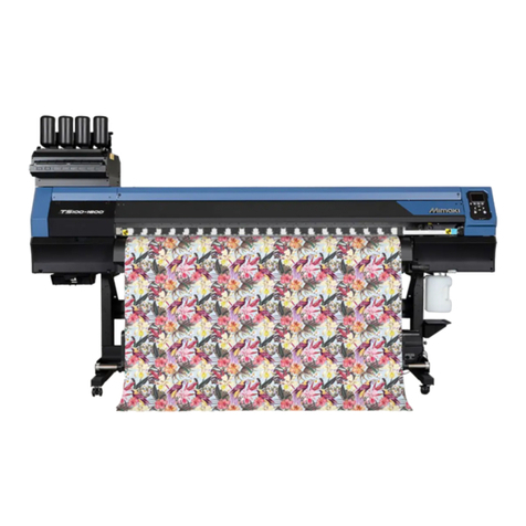
MIMAKI JV400-LX DC1 User manual

MIMAKI ENGINEERING CO., LTD.
URL:http://eng.mimaki.co.jp
D901995-10
Heater Replacement Manual
JV400-LX DC1

© 2013 MIMAKI ENGINEERING CO.,LTD. P.1
JV400-LX DC1
Heater Replacement Manual
Date
2013.07.11
Manual Ver
1.00
Remark
Status Index Rev.
changes
Released - - New issued

© 2013 MIMAKI ENGINEERING CO.,LTD. R.1.0 P.1
JV400-LX DC1 Heater Replacement
Purpose
Replace the heater to eliminate uneven drying on left and right ends, and to improve drying performance.
Tools
1. Phillips screwdriver
2. 4mm hex wrench
3. Nippers
4. Cutter
5. Hydraulic punch (provided by development divisions)
6. Dielectric strength tester (provided by development divisions)
7. Alcohol (for degreasing)
8. Tester (if a dielectric strength tester is not available)
9. Acetate tape
Replacement parts
1. Platen cover R
2. P Platen
3. Platen cover F
4. Drying heater
5. Front cover, Drying fan side plate and etc. covers.
6. W filter parts
Work procedure (outline)
1. Preliminary work(Removal the covers and drying heater)・・・Work time: 30 minutes
2. Heater replacement(Pre, Print, After)・・・Work time: 60 minutes
3. Drying heater, cover installation・・・Work time:30 minutes
4. W filter installation・・・Work time:15 minutes
5. Parameter changes・・・Work time:10 minutes
6. Operation check・・・Work time:20 minutes
Total work time;165 minutes (2 hours 45 minutes)
*Heater replacement should be performed by two people.
1.
2.
3.
4.
5. 6.
Model
JV400-LX
Issued
2013.06.06
Revised F/W ver Remark
1.0
Rev.

© 2013 MIMAKI ENGINEERING CO.,LTD. R.1.0 P.2
JV400-LX DC1 Heater Replacement
Work procedure (detailed)
1. Preliminary work
1. Remove the exterior cover.(Right maintenance cover C,
Right maintenance cover U, Left maintenance cover U, Y
cover RR, Rear cover LU, Front cover 200L160(130), Y
cover 200C160(130))
2. Remove the Drying heater and Drying fan side plate.
Right maintenance
cover C
Right maintenance cover U
Left maintenance cover U
Y cover RR
Front cover 200L160(130)
Y cover 200C160(130)
Drying fan side plate
Drying heater
Model
JV400-LX
Issued
2013.06.06
Revised F/W ver Remark
1.0
Rev.

© 2013 MIMAKI ENGINEERING CO.,LTD. R.1.0 P.3
JV400-LX DC1 Heater Replacement
2.Replacement of the heater
1) Remove the wiring.
1. Disconnect the thermistor cable from the heater.
Remove the thermistor cables(x3).
2. Disconnect the cables connected to CN1, CN4, CN5, and
CN8 on the heater PCB, and remove the clamped wires.
Remove the screws in the 2 locations shown in the figure
to the left, and remove the heater PCB partition plate.
2) Removal the Platen cover F (should be performed
by 2 people)
3. Disconnect the relay cable (connector) for the cover
sensor, and remove the front cover frames on the left and
right sides.
Thermistor x3
ST wiring cover
If the machine has an ST wiring cover
installed, the ST wiring cover should be
removed as the first step.
Wiring of the FAN
Screw x2
Heater PCB partition plate
CN1 color : Blue (Pri)
CN4 color : White/Yellow
(Print)
CN5 color : Green/Red
(Print)
CN8 color : Black
(After)
Heater PCB cooling fan
If the machine has a cooling fan installed on
the heater PCB, remove the fan's wiring.
Connector
Right/Left
Front cover frame
Model
JV400-LX
Issued
2013.06.06
Revised F/W ver Remark
1.0
Rev.

© 2013 MIMAKI ENGINEERING CO.,LTD. R.1.0 P.4
JV400-LX DC1 Heater Replacement
4. Remove the Cover sensor BKT from the front cover
frames removed in Step 3.
5. Remove the screws shown in the figure on the left (160: 9
locations, 130: 8 locations), and then remove Platen cover
F.
3) Removal the Platen cover R (should be performed
by 2 people)
6. Remove the screws shown in the figure on the left (160:
12 locations, 130: 11 locations), and then remove Platen
cover R.
Cover sensor BKT
You might need to
remove the entire bush.
On some machines, the relay cable cannot be
removed. In such cases, remove the cable
together with the entire bush.
Fixing position
Fixing position
Front side
Model
JV400-LX
Issued
2013.06.06
Revised F/W ver Remark
1.0
Rev.

© 2013 MIMAKI ENGINEERING CO.,LTD. R.1.0 P.5
JV400-LX DC1 Heater Replacement
4) Remove and modify the Platen.
7. Remove the screws shown in the figure on the below
(160: 14 locations, 130: 12 locations), and then remove P
platen.
8. Remove the media holder ( x2) from P platen removed in
Step 7. 。
9. When using the hydraulic punch, first remove the MS
cover (2 screws). Otherwise, the MS cover will interfere
with the hydraulic punch.
10. Use the hydraulic punch to make a square hole in the left
end of the P board. (Use a 16.8mm □punch.)
Place the punch against the grooved area, and punch a
hole with the dimensions shown in the figure on the
bottom left.
Media holder
These parts will be used again. Take care not
to lose them.
MS cover
ンチにて穴を16.8mm
ンチにて穴を20mm
Place against the grooved
area
Place against the grooved
area
Chips are left when punching holes. Be sure
to clean the area around the equipment after
punching holes.
Model
JV400-LX
Issued
2013.06.06
Revised F/W ver Remark
1.0
Rev.

© 2013 MIMAKI ENGINEERING CO.,LTD. R.1.1 P.6
JV400-LX DC1 Heater Replacement
11.Use acetate tape to protect the area around the punched
location.
12. Apply Bantekuto to both ends inside the platen.
Use alcohol to degrease the surface where Bantekuto will
be applied.
5) Wiring inside the platen
13.Install the finger guard on the suction fan (2 locations).
Degrease with alcohol
Apply against this surface
パンチにて穴を開Secure nut x2
パンチにて穴を開
Finger guard
Front side
Model
JV400-LX
Issued
2013.06.06
Revised
2013.06.20
F/W ver Remark
1.1
Rev.

© 2013 MIMAKI ENGINEERING CO.,LTD. R.1.1 P.7
JV400-LX DC1 Heater Replacement
14.Use a cable tie to bundle the wires coming out from the
center of the platen.
15.Use a cable tie to bundle the wires on the thermostat.
16.Apply acetate tape over the wires bundled in Step 15.
17. Wire the platen heater cable and extension cable.
Connect cables of the same color between the heater
cable and extension cable.
圧パンチにて穴を開けAcetate tape
Apply the tape over the wires and all the way
to the bottom of the metal plate.
圧パンチにて穴を開けるExtension cable side
パンチにて穴を開Platen side
パンチにて穴を開Platen side
パンチにて穴を開けるExtension cable side
Model
JV400-LX
Issued
2013.06.06
Revised
2013.06.20
F/W ver Remark
1.1
Rev.

© 2013 MIMAKI ENGINEERING CO.,LTD. R.1.0 P.8
JV400-LX DC1 Heater Replacement
18.Cover both the heater cable and extension cable with a
corrugated tube.
Take care to prevent the sections of heater wire that are
folded back on themselves from sticking out of the tube.
19. Fix a cable tie with a screw, and then fix the cables with
the cable tie.
The routing for each cable size is shown in the photo-
graphs below.
●Size 130:
Fix with cable ties in the areas indicated with red circles in
left figure. (2 locations)
パンチにて穴を開けるExtension cable side
パンチにて穴を開Platen side
パンチにて穴を開けるCorrugated tube
Take care to prevent the sections that are folded
back on themselves from
sticking out of the tube.
パンチにて穴を開Platen side
パンチにて穴を開けるExtension cable side
パンチにて穴を開Cable tie
パンチにて穴をFix with screw
Bundle the cable
Use screws to fix cable ties
to the areas marked with red
circles in the figure to the
left, and then use the cable
ties to bundle the cables.
Connection position for relay connector
Face the slit on the tube
toward the front
Model
JV400-LX
Issued
2013.06.06
Revised F/W ver Remark
1.0
Rev.

© 2013 MIMAKI ENGINEERING CO.,LTD. R.1.0 P.9
JV400-LX DC1 Heater Replacement
●Size 160:
Fix with cable ties in the areas indicated with red circles in
left figure. (3 locations)
20.Wrap acetate tape around the areas where the cables
from the relay connectors are exposed.
21.Since the new platen has a thermistor installed, dispose of
the one installed on the old heater.
For size 160, use an extension cable.
22. Excess cable from the heater should be routed along the
outside of the platen collected under the cover.
6) Attachment of the P platen
23.Install the media holders removed in Step 8 onto the
platen.
Connection position for relay connector
Face the slit on the tube
toward the front
パンチにて穴を開Acetate tape
Collect cable under the cover
Model
JV400-LX
Issued
2013.06.06
Revised F/W ver Remark
1.0
Rev.

© 2013 MIMAKI ENGINEERING CO.,LTD. R.1.0 P.10
JV400-LX DC1 Heater Replacement
24.Fix the platen with screw. (See the figure below.)
Order to tighten screws: In order from ①to ③, and then
as desired.
25.Confirm that the media holders move smoothly on the top
of the platen. If they do not move smoothly, adjust them by
loosening the screws indicated by red circles in the
photograph on the bottom left.
7) Attachment of the Platen cover R
Take care to prevent heater wiring from
becoming pinched in metal plates.
Take care not to tighten screws too tight.
䐟㼀㼑㼙㼜㼛㼞㼍㼞㼕㼘㼥㻌㼠㼕㼓㼔㼠㼑㼚㼀㼑㼙㼜㼛㼞㼍㼞㼕㼘㼥㻌㼠㼕㼓㼔㼠㼑㼚
䐡㻲㼕㼤㻲㼕㼤
䐠㻲㼕㼤㻌㻌㻌㻌㻌㻌㻌㻲㼕㼤㻌㻌㻌㻌㻌㻌㻌
䐟
䐠
䐡
Adjust by loosening
Take care to prevent heater wiring from
becoming pinched in metal plates.
If you are performing this work alone,
remove Y cover 200R(160 or 130) before
starting this work.
Model
JV400-LX
Issued
2013.06.06
Revised F/W ver Remark
1.0
Rev.

© 2013 MIMAKI ENGINEERING CO.,LTD. R.1.0 P.11
JV400-LX DC1 Heater Replacement
26.Temporarily tighten the screws.
27.Raise the clamp lever, and move the roll holder to the
end.
28. Install platen cover R on the temporarily tightened
screws. Push the cover until it touches the screws, and
then fix one of the screws.
29. Confirm that no cables are pinched in the cover, and then
move the cables to the outside of the boards at the left
and right ends.
30.Push the platen cover against the screws, and then fix the
temporarily tightened screws.
31.Make sure the space below the platen cover is the same
width all the way across (rear of the machine), and then fix
the temporarily tightened screws.
Front side
Temporarily tighten
Push until it touches
Rear side
Equal spacing under the platen
Model
JV400-LX
Issued
2013.06.06
Revised F/W ver Remark
1.0
Rev.

© 2013 MIMAKI ENGINEERING CO.,LTD. R.1.0 P.12
JV400-LX DC1 Heater Replacement
8) Attachment of the Platen cover F
32.Temporarily tighten the screws on the platen cover F
base. (160: 5 locations, 130, 4 locations)
33.Fit platen cover F on the temporarily tightened screws,
and move the cables to the outside of the boards at the
left and right ends.
34.Fit platen cover F on the platen, and fix the screws. (4
locations)
35.Make sure the spaces on the left and right below platen
cover F are the same width all the way across, and then
fix the temporarily tightened areas.
Take care to prevent heater wiring from
becoming pinched in metal plates.
Equal spacing on the right/left side
Model
JV400-LX
Issued
2013.06.06
Revised F/W ver Remark
1.0
Rev.

© 2013 MIMAKI ENGINEERING CO.,LTD. R.1.0 P.13
JV400-LX DC1 Heater Replacement
9) Heater cable wiring
Wire the heater cable in the combinations shown
below.
・Connect the Pre-heater (blue) to heater PCB CN1.
・Connect the Print heater (red/green, white/yellow) to
heater boards CN4, CN5.
・Connect the After heater (black) to heater board CN8.
Wire the thermistor cable in the combinations shown
below.
・Connect the thermistor (blue connector) to the blue
cable.
・Connect the thermistor (white connector) to the white
cable.
・Connect the thermistor (black connector) to the black
cable.
3.Attachment of the Drying heater and cover
1. attach the Drying fan side plate.
2. Attach the Drying fan heater.
(For details, see the installation guide.)
Attachment of the cover.
3. attach the Sensor cover BKT and connect the cover sen-
sor cable.
4. Attach the Front cover.
Blue
Green Red
Yellow White
Green
Black
Red
Colors of cables to insert
in heater board
connectors
Reinstall the original screws for the belt on
the drying fan side plate.
Take care to not drop the Drying heater.
Doing so could result in damage. (This
work should be performed by 2 people.)
Cover sensor BKT
Front cover fulcrum pin
Do not mistake the Right/Left sides
Reinstall the original cover fulcrum pin that
was installed on the front cover.
Note that the cover fulcrum pin is shaped
differently on its left and right sides.
(If the pin is not installed correctly, the front
cover cannot be opened/closed correctly.)
Model
JV400-LX
Issued
2013.06.06
Revised F/W ver Remark
1.0
Rev.

© 2013 MIMAKI ENGINEERING CO.,LTD. R.1.0 P.14
JV400-LX DC1 Heater Replacement
5. After closing the front cover, confirm that the sensor is
pressing the dog correctly.
If not, adjust it by loosening the screws shown in the fig-
ure on the left. (2 locations)
6. Connect the cables of the Heater cover, drying fan and
thermo sensor.
7. Attach the bush to the heater skirt.
8. Attach the Heater cover U.
Temporarily tighten the screws on the drying heater Assy.
Hook the U groove at the bottom of the heater cover on
this screw.
Then, fix the screws.
Attach the bush
Heater cover U
Heater cover U
Hook the U groove
Screw
Temporarily tighten
Model
JV400-LX
Issued
2013.06.06
Revised F/W ver Remark
1.0
Rev.

© 2013 MIMAKI ENGINEERING CO.,LTD. R.1.0 P.15
JV400-LX DC1 Heater Replacement
9. Attach the heater skirt.
Temporarily tighten the screws on the Drying heater Assy.
Hook the U groove at the bottom of the heater skirt on this
screw.
Then, fix the screws.
Fix the Heater skirt to the Drying fan side plate with
screws.
Connect the External heater
10.Lock the cable 150mm from the connector.
Remove the ring, pass the cable through, and then
connect the cable.
Secure the ring again.
Fix the earth wire (green wire) with a screw.
11.Connect the cables of the Fan and thermo sensor.
Heater skirt
Heater skirt
Hook the U groove
Screw
Temporarily tighten
150mm
Earth wire
Pass the wire through the bush
Left:Red
Center:Blue
Model
JV400-LX
Issued
2013.06.06
Revised F/W ver Remark
1.0
Rev.

© 2013 MIMAKI ENGINEERING CO.,LTD. R.1.0 P.16
JV400-LX DC1 Heater Replacement
12.Apply the included seals, shown below, to the left and
right ends of the platen.
4.Attachment of the W filter
1. Remove the Rear cover LU and Light maintenance cover
200.
2. Cut the tubes in the location shown in the figure below.
3. Remove the Chamber bottle Assy. (The 2 screws will be
used again.)
4. Attach the W filter Assy. (x 2 screws.)
)。
Left side
Right side
Cut 2 tubes
Cut 2 tubes
Cut 2 tubes
Pressure control pump
Cut 2 tubes
Assy.
Assy.
Model
JV400-LX
Issued
2013.06.06
Revised F/W ver Remark
1.0
Rev.

© 2013 MIMAKI ENGINEERING CO.,LTD. R.1.0 P.17
JV400-LX DC1 Heater Replacement
5. Install the fitting on one end of the W filter tubes (attached
to the L-shaped pipe, 2 tubes). (There is already a fitting
on the other end.)
6. Remove the filters of No.7 and No.8.。
7. Connect the Extension tube and W filter tube to the W
filter.
There are two types of tubes, "7" and "8", with different
lengths. Looking at the machine from the rear, install the
No. 7 tube on the left-side filter.
8. Attach the Left cover 200 and New rear cover LULx.
Perform curing to prevent ink leakage.
No.7
No.8
To extension tube
To W filter tube
Perform curing to prevent ink leakage.
P
Remove
W filter
W filter tube with
Extension tube
Attach the
Fitting
Check valve
Pump
Ink supply
Tube tag「8」
Tube tag「7」
Extension tube
W filter
L connector
Model
JV400-LX
Issued
2013.06.06
Revised F/W ver Remark
1.0
Rev.

© 2013 MIMAKI ENGINEERING CO.,LTD. R.1.0 P.18
JV400-LX DC1 Heater Replacement
5.Changing of the Parameter
1. Select #PARAMETER/SYSTEM param. in the Function
menu, and change No.12DC1 to 1.
2. Restart the machine.
6. Checking operations
1) Checking dielectric strength voltage
1. Turn the power switch ON, and connect the jig to inlet 1.
2. Press the START key, and turn the output voltage
adjustment knob to adjust the voltage to 15kV.
3. Press the STOP key.
4. Press the START key to start the test.
5. If the test results are OK, the DANGER lamp goes off and
"OK" appears on the test results LED.
6. Perform the same test again for inlet 2.
7. Confirm that the DANGER lamp is off, and then turn the
power switch off.
If a dielectric strength isolation voltage meter is not
available, use a tester to check for short circuits.
FUNCTION
#PARAMETER [ENT]
#PARAMETER
SYSTEM param.[ENT]
SYSTEM param.
0=0 R GRID
ENTER key
SYSTEM param.
12=0 DC1
SYSTEM param.
12=0 1
SYSTEM param.
12=0 DC1
Select No.12 DC1 with UP/DOWN
key
Select 1 with UP/DOWN key
Press the END key several times
to exit
ENTER key
ENTER key
ENTER key
When taking measurements, do not touch the machine with your hands. Doing so could
result in electric shock.
Take sufficient care that the machine is touched by nobody in the nearby area, and not only
the person taking measurements.
After testing is complete, confirm that the DANGER lamp on the resistance voltmeter is off
before touching the machine.
Powerswitch
Startkey
Stopkey
DANGERlamp
ResultLED
Adjustmentknob
Voltagemeter
Model
JV400-LX
Issued
2013.06.06
Revised F/W ver Remark
1.0
Rev.
Table of contents
Other MIMAKI Heater manuals