Mincey Marble Napoli Series User manual

Mincey Marble Mfg., Inc.
1940 New Harvest Road
Gainesville, GA 30507
Ph: 800.533.1806
Fx: 770.531.0935
www.minceymarble.com
MATERIALS / TOOLS NEEDED CHECKLIST
PRE-INSTALLATION PIECES / PARTS LIST
ENCLOSURE SYSTEM INSTALLATION
Installation Instructions for Mincey Marble Manufacturing’s
Reversed Napoli Straight Barn Door Shower Enclosures
ATTENTION: Prior to starting the installation, please read through these instructions. This will
help avoid any unneccesary breakage. Any breakage due to handling or installing this enclosure
system is the responsibility of the installer and is not covered under the Mincey Warranty. Mincey
recommends that two people are used to install this shower enclosure system due to the weight
and fragility of the glass panels. Mincey also recommends that you protect the glass, especially
the bottoms, and the shower pan during installation. If your doors have frosted glass, the frosted
side of the glass goes to the outside of the shower.
These installation instructions apply to the Mincey Reversed Napoli Straight Barn Door Shower Enclosure System.
The Reversed Napoli Straight Barn Door Shower Enclosure System is to be used when the shower door closes
opposite the shower head and wet wall. In these instructions we are going to use an example with a 58” wide
VKRZHUZLWKWKHRSHQLQJGRRUORFDWHGRQWKHULJKWVLGHRIWKHVKRZHUDQGWKH¿[HGJODVVSDQHORQWKHOHIW
All Drawings Are Not To Scale.
8QFUDWHDOORIWKHPDWHULDOVDQGFRQ¿UPWKDWDOORIWKHSDUWVDQGSLHFHVDUHSUHVHQW The Required
Tools are listed below. The contents of the Hardware Kit are listed below. The Parts Diagram is on the following
page. Before you begin the installation, make sure that all of the pertinent surfaces are clean and free of dust,
debris and any shavings. After you perform any drilling, you will want to make sure the surfaces are clean again
- this includes the Shower Pan and the Shower Panel Walls.
INCLUDED IN THE HARDWARE KIT
MATERIALS / TOOLS NEEDED
DRILL (CORDED OR CORDLESS),
3/16” 1/4” & 5/16” MASONRY
DRILL BITS
TAPE MEASURE
PENCIL
LEVEL
CAULK GUN,
100% SILICONE
RUBBER MALLET
PORTABLE BAND SAW
(PREFERRED METHOD)
HACK SAW- OR -
PHILLIPS HEAD SCREWDRIVER LOCTITE
BLUE 243
THREADLOCKER
FIXED GLASS
BRACKET QTY: 1
ROLLERS QTY: 4
GUIDE RAIL HOLDER TOOL QTY: 1
DOOR STOPS
QTY: 2
ALLEN WRENCHES:
1/4”, 3/16”, 1/8”, 5/32”, 3/32”
CLEAR SETTING
BLOCKS
QTY: 4
FLAT HEAD SCREWS:
1 1/8 X 3/16” (QTY: 2)
1 1/8 X 1/8” (QTY: 5)
PAN HEAD SCREWS:
1 1/4 X 1/8” (QTY: 2)
2 X 3/16” (QTY: 2)
WALL ANCHORS:
5/16” (QTY: 2)
LIGHT BLUE
5/16” (QTY: 2)
CLEAR
3/16” (QTY: 7)
GREEN
GUIDE RAIL
END CAPS
QTY: 2
DIVERTER
BAR QTY: 1
DOOR GUIDE QTY: 1
(Set to position 12 on
bottom)

If you have any questions, please call MINCEY MARBLE CUSTOMER SERVICE at 1-800-533-1806.
Mincey Marble Mfg., Inc. |1940 New Harvest Road, Gainesville, GA 30507 |800.533.1806 |minceymarble.com
SHOWER ENCLOSURE PARTS LIST
ASSEMBLY CODE ASSEMBLY NAME QTY
1 FIXED GLASS PANEL 1
2 SLIDING GLASS PANEL 1
3 VERTICAL U CHANNEL 1
4 BOTTOM U CHANNEL 1
5DIVERTER BAR1
6 FIXED GLASS BRACKET 1
7GUIDE RAIL1
8 GUIDE RAIL END CAPS 2
9 ROLLERS 4
10 DOOR STOPS 2
11 DOOR GUIDE 1
12 SHORT F-SEAL 1
13 LONG F-SEAL 1
14 BUBBLE SEAL 1
15 5/16" CLEAR WALL ANCHORS 2
16 5/16" BLUE WALL ANCHORS 2
17 3/16" GREEN WALL ANCHORS 7
18 CLEAR SETTING BLOCKS 4
19 HANDLE 1
20 2" X 3/16" PAN HEAD SCREWS 2
21 1 1/4" X 1/8" PAN HEAD SCREWS 3
22 1 1/8" X 1/8" FLAT HEAD SCREWS 5
PRE-INSTALLATION PIECES / PARTS LIST (cont.) 2
(1)
(2)
(3)
(4)
(5)
(6)
(7)
(8) (9)
(10)
(11)
(12)
(13)
(14)
(15)
(16)
(17)
(18)
(19)
(20)
(22)
(21)
(8)
(10)
(15)
(20)

If you have any questions, please call MINCEY MARBLE CUSTOMER SERVICE at 1-800-533-1806.
Mincey Marble Mfg., Inc. |1940 New Harvest Road, Gainesville, GA 30507 |800.533.1806 |minceymarble.com
NAPOLI STRAIGHT BARN DOOR ENCLOSURE SYSTEM INSTALLATION 3
These instructions are to be followed assuming the Shower Pan is level and the Walls are plumb. In these
instructions and as an example, we will be installing the Napoli Straight Barn Door Shower Enclosure in a 58”
ZLGHVKRZHU$IWHU\RXKDYHFRQ¿UPHGWKDWDOORIWKHUHPDLQLQJSDUWVDQGSLHFHVDUHSUHVHQW\RXDUHUHDG\WR
begin by preparing to install the LEFT VERTICAL U CHANNEL.
Begin by making marks on the top of the Shower Pan Curb 3/8” from the inside edge of the Curb. Place marks
at the Left Panel Wall, in the Center of the Pan and one in-between those two marks. Hold LEFT VERTICAL U
CHANNEL up against the Left Wall Panel, plumb with the Level and mark where the three holes are to be
drilled in the Top, Center and Bottom locations.
PLUMB LEFT VERTICAL
U CHANNEL WITH LEVEL,
MARK HOLE LOCATIONS
AND REMOVE
SCREW
HOLES
HAMMER
IN ALL
THREE
ANCHORS
SCREW
IN U
CHANNEL
REMOVE U
CHANNEL, DRILL HOLES
WITH 5/16” MASONRY
BIT, HAMMER IN
WALL ANCHORS
CLEAN DEBRIS AND
SHAVINGS, PLACE U
CHANNEL AND SCREW
INTO PLACE
1 1/8”
FLAT HEAD
SCREWS
3/16”
GREEN
WALL
ANCHORS
PAN
RUN A BEAD OF 100% SILICONE
ON THE BOTTOM OF THE BOTTOM
U CHANNEL AND CAREFULLY PLACE
ON THE 3/8” MARKS ON THE CURB
3/8”
FROM
INSIDE
EDGE OF
CURB
MEASURE
AND MARK
IN ALL
THREE PAN
CURB
LOCATIONS
PAN
Next, run a bead of 100% Silicone the length of the bottom of the BOTTOM U CHANNEL. Carefully place the
BOTTOM U CHANNEL onto the Shower Pan Curb on the edge of the marks at 3/8” from the inside of the shower
FXUE7KH%277208&+$11(/VKRXOGEHÀXVKDJDLQVWWKH9(57,&$/8&+$11(/DOLJQLQJWKHLUFHQWHUVVRWKDW
the Fixed Glass Panel will slide into place into both channels.
Then, you will place TWO CLEAR SETTING BLOCKS near the ends of the BOTTOM U CHANNEL for the Fixed
Glass Panel to rest on. These CLEAR SETTING BLOCKS can be cut and doubled-up if necessary for leveling.
MAKE SURE BOTTOM U CHANNEL
IS FLUSH WITH THE VERTICAL U
CHANNEL AND THE CHANNELS ARE
ALIGNED TO ACCEPT THE FIXED
GLASS PANEL
PLACE SETTING
BLOCKS INTO
BOTTOM U CHANNEL
TO LEVEL FIXED
GLASS PANEL
VERTICAL U CHANNEL
AND BOTTOM U
CHANNEL

If you have any questions, please call MINCEY MARBLE CUSTOMER SERVICE at 1-800-533-1806.
Mincey Marble Mfg., Inc. |1940 New Harvest Road, Gainesville, GA 30507 |800.533.1806 |minceymarble.com
NAPOLI STRAIGHT BARN DOOR ENCLOSURE SYSTEM INSTALLATION (cont.) 4
1RZ\RXDUHUHDG\WRLQVWDOOWKH),;('*/$663$1(/<RXZLOOEHJLQE\WHVW¿WWLQJWKH),;('*/$663$1(/
3ODFHWKHSDQHOLQWRWKHWKH9HUWLFDODQG%RWWRP8&KDQQHOVPDNLQJVXUHWKHSDQHOLVÀXVKWRWKHZDOOThe
hole closest to the edge of the FIXED GLASS PANEL is to be located furthest from the Wall. Check
for level. Add CLEAR SETTING BLOCKS into the Bottom U Channel at either end to Level the FIXED GLASS
PANEL. You can trim and stack the CLEAR SETTING BLOCKS if necessary to Level the panel. Once Level,
place the FIXED GLASS PANEL BRACKET and mark where to drill the hole.
LEVEL FIXED
GLASS PANEL
WITH CLEAR
SETTING
BLOCKS,
THEY CAN BE
DOUBLED IF
NECESSARY
MAKE SURE
FLUSH TO
WALL
PAN
FILL THE CORNER AREA
WHERE THE BOTTOM U
CHANNEL AND THE
VERTICAL U CHANNEL
MEET WITH 100%
SILICONE.
THEN, CAREFULLY REPLACE
THE FIXED GLASS PANEL
BACK INTO THE U
CHANNELS MAKING SURE IT
IS FLUSH WITH THE WALL.
FILL WITH
100% SILICONE
AFTER LEVELING THE FIXED GLASS
PANEL, PLACE THE FIXED GLASS PANEL
BRACKET IN POSITION. MARK THE
HOLE WHERE TO DRILL THE
MOUNTING SCREW ON THE CURB.
CAREFULLY REMOVE THE BRACKET
AND THE FIXED GLASS PANEL.
FIXED GLASS PANEL
MARK BRACKET
HOLE
DRILL HOLE WITH
3/16” MASONRY BIT,
CLEAN UP DEBRIS,
FILL HOLE WITH
SILICONE, HAMMER
IN GREEN 3/16”
PLASTIC ANCHOR,
CLEAN EXCESS
SILICONE
INSTALL THE
FIXED GLASS
PANEL BRACKET
AND CLEAN
ANY EXCESS
SILICONE
1H[W\RXDUHUHDG\WRLQVWDOOWKH'225*8,'(&RQ¿UPWKH'225*8,'(LV
set in the #12 Position by looking at the bottom. Place the DOOR GUIDE at
1 7/16” from the Outside edge of the Fixed Glass Panel to the Inside DOOR
GUIDE channel, align the Right Side Screw Hole and the Fixed Glass Panel
Bracket Screw Hole and Mark the outline around the DOOR GUIDE. Remove
the DOOR GUIDE.
Place the DOOR GUIDE and Mark the holes to be drilled on the Shower Pan
Curb. Drill holes using a 1/4” Masonry Bit, Fill holes with 100% Silicone,
Hammer in Plastic Anchors, Clean any excess silicone, Install DOOR GUIDE
with 1 1/8” x 3/16” Flat Head Screws.
Measure, Trim and Install the DIVERTER BAR using
Silicone and Pressing into place. The Bubble Edge
installs to the outside of the shower.
OUTSIDE FIXED
GLASS PANEL TO
INSIDE DOOR
GLASS MEASURES
1 7/16”
LINE UP SCREW HOLES
MARK
OUTLINE
OF DOOR
GUIDE
RUN A HEALTHY BEAD OF
SILICONE ON ENTIRE BOTTOM
OF THE DIVERTER BAR AND
PRESS INTO PLACE, THEN CLEAN
MEASURE FROM THE DOOR GUIDE TO THE WALL
PANEL, TRIM THE DIVERTER BAR TO FIT
BUBBLE EDGE TO OUTSIDE OF SHOWER
If you have any questions, please call MINCEY MARBLE CUSTOMER SERVICE at 1-800-533-1806.
Mincey Marble Mfg., Inc. |1940 New Harvest Road, Gainesville, GA 30507 |800.533.1806 |minceymarble.com
NAPOLI STRAIGHT BARN DOOR ENCLOSURE SYSTEM INSTALLATION (cont.) 5
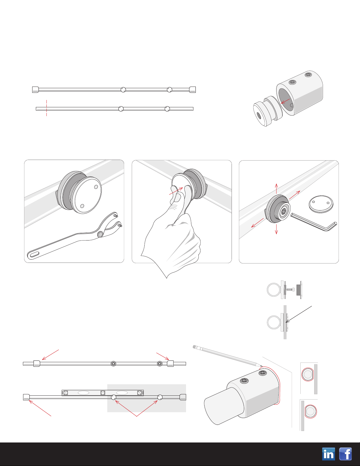
You are now ready to install the GUIDE RAIL. First, measure 72” up from the Shower Pan and measure the
distance between the Wall Panels. In this example, the measurement will be 58”. The Napoli Shower Enclosure
GUIDE RAIL measures 60” when fully assembled with the End Caps installed. Therefore in this example, 2” will
QHHGWREHWULPPHGRRIWKH*8,'(5$,/7ULP´RWKH*8,'(5$,/IURPWKHHQGZKHUHWKH6KRZHU
Door will be located, not the end to be installed to the Wall on the Fixed Glass Panel side.
(Trim the end where the Fixed Glass Panel Holders are not located.) Then, disassemble the END CAPS.
Disassemble the two GUIDE RAIL END CAPS and slide the Outside Sleeves onto the
GUIDE RAIL without the Inner Mounting Cogs. Install the GUIDE RAIL onto the Fixed
Glass Panel. LEVEL the GUIDE RAIL and snug the GUIDE RAIL HOLDERS. Push the
GUIDE RAIL END CAPS to the Wall Panels and Mark the ends by outlining the END CAPS
onto the Wall Panels. Make sure the END CAP on the FIXED GLASS PANEL side
has the FLAT SIDE facing the Glass Panel. The Shower Door side END CAP
should have the FLAT SIDE facing outward from the Shower, towards where
the Shower Door will be installed.
DISASSEMBLE THE GUIDE
RAIL HOLDERS
USE TOOL TO CAREFULLY
UNSCREW CAPS
USE FIRM
THUMB
PRESSURE TO
PREVENT
SLIPPAGE AND
SCRATCHING
THE CAP
WHEN
LOOSENING
OR TIGHTENING
THE CAP
USE 1/4” ALLEN WRENCH
TO TIGHTEN WHEN LEVEL
LOOSEN SLIGHTLY TO
ADJUST
Next, disassemble the GUIDE RAIL by carefully removing the Fixed Glass Panel Holders using the Fixed Glass
Panel Holders Tool. Use thumb pressure to carefully remove the Holders without scratching them by allowing
the tool to slip out of the designated holes.
FULLY ASSEMBLED, THE GUIDE RAIL MEASURES 60”
IN THIS EXAMPLE THE SHOWER MEASURES 58”
TRIM 2” OFF THE END WHERE THE SHOWER DOOR WILL BE,
WHEN FULLY RE-ASSEMBLED, THE GUIDE RAIL WILL MEASURE 58”
DISASSEMBLE THE GUIDE
RAIL END CAPS USING
THE 5/32” ALLEN
WRENCH
SLIDE GUIDE RAIL END CAPS ONTO RAIL WITH
FLAT ENDS TOWARDS THE WALL PANELS
INSTALL GUIDE RAIL ONTO
FIXED GLASS PANEL, SNUG
GLASS PANEL HOLDERS AT LEVEL
PUSH END CAPS TO WALL
PANELS AND MARK OUTLINES
RIGHT
SIDE
END CAP
FLAT SIDE
TO GLASS
PANEL
LEFT SIDE
END CAP
FLAT SIDE
TO GLASS
DOOR
MARK END CAPS
ON WALL WITH
OUTLINE
VIEW IS FROM INSIDE THE SHOWER
RIGHT SIDE
SHOWN
GUIDE
RAIL
INSTALLED
ONTO
FIXED
GLASS
PANEL

If you have any questions, please call MINCEY MARBLE CUSTOMER SERVICE at 1-800-533-1806.
Mincey Marble Mfg., Inc. |1940 New Harvest Road, Gainesville, GA 30507 |800.533.1806 |minceymarble.com
6
NAPOLI STRAIGHT BARN DOOR ENCLOSURE SYSTEM INSTALLATION (cont.)
After you have marked where the Guide Rail End Caps are located on the Wall Panels. Re-assemble the End
&DSVZLWKWKHUHFHVVHGVLGHRIWKH(QG&DS&RJWRWKHLQVLGHDQGWKHÀDWVLGHWRWKH:DOO3DQHO+ROG(QG
Caps back in place on the wall and Mark the inside holes, where you will drill. Drill End Cap mounting holes
into Wall Panels using 5/16” Masonry Bit, Hammer in Clear 5/16” Wall Anchors and Install End Cap Cogs.
NOTE: LOCTITE BLUE 243 is required
as a threadlocker to secure the
installation of the Roller Screws.
LOCTITE is NOT provided with the doors,
but is readily available at many hardware
stores, online at mscdirect.com or through
Mincey Marble at 1-800-533-1806.
FLAT END GOES
TOWARDS WALL
RE-ASSEMBLE
END CAPS
DRILL HOLE USING 5/16”
MASONRY BIT, HAMMER
IN CLEAR 5/16” WALL
ANCHOR
MARK HOLES,
REMOVE
END
CAPS
RECESSED END
GOES TOWARDS
GUIDE RAIL
WALL PANEL
INSTALL END CAP
COGS WITH
2” x 3/16”
PAN HEAD SCREWS
With the Guide Rail End Cap Cogs installed to the Wall Panels, you can now assemble the ROLLERS onto the
GLASS DOOR. Disassemble the ROLLERS using the 3/16” Allen Wrench. Install the Top Two ROLLERS into
the top two factory holes in the GLASS DOOR with the ROLLERS on the Inside of the GLASS DOOR and with
the Door Handle to the Right. Be sure to use LOCTITE Blue 243 threadlocker when installing the
ROLLERS onto the GLASS DOOR.
CAM LOBE UP = GLASS UP
CAM LOBE DOWN = GLASS DOWN
DISASSEMBLE ROLLER
USING 3/16” ALLEN
WRENCH
FELT WASHERS
TOOTH WASHER
ASSEMBLE TO GLASS
PANEL USING LOCTITE
BLUE 243 ON SCREW
INSTALL THE ROLLERS
IN THE GLASS DOWN
POSITION / CAM
DOWN POSITION
ONCE THE DOOR IS
INSTALLED ADJUST
CAM LOBE WITH A 1/8”
ALLEN WRENCH FOR
FLUSH, LEVEL
OPERATION
CAM LOBE
BACK
OF SHOWER
FRONT
OF SHOWER

If you have any questions, please call MINCEY MARBLE CUSTOMER SERVICE at 1-800-533-1806.
Mincey Marble Mfg., Inc. |1940 New Harvest Road, Gainesville, GA 30507 |800.533.1806 |minceymarble.com
7
NAPOLI STRAIGHT BARN DOOR ENCLOSURE SYSTEM INSTALLATION (cont.)
You are now ready to re-install the Guide Rail. Slide the two DOOR STOPS onto the Guide Rail tightening them
VOLJKWO\VRWKH\GRQRWVOLGHR$OVRVOLGHWKH*XLGH5DLO(QG&DS6OHHYHVEDFNRQWRWKH*XLGH5DLO5HLQVWDOO
the Guide Rail with the Fixed Glass Panel Holders. Slide the Guide Rail End Caps back to the Wall Panels and
tighten everything making sure the Guide Rail remains Level.
THANK YOU FOR USING OUR MINCEY MARBLE PRODUCT! WE APPRECIATE YOUR BUSINESS!
SLIDE DOOR STOPS
ONTO GUIDE RAIL,
TIGHTEN SLIGHTLY
TO HOLD IN PLACE
SLIDE END CAPS TO
WALLS AND TIGHTEN,
MAKE SURE TO
REMAIN LEVEL
CAM LOBE UP = GLASS UP
CAM LOBE DOWN = GLASS DOWN
Install DOOR F SEALS using Rubber Mallet to tap into place. The SHORT F SEAL installs on the Fixed Glass Panel
with the FIN towards the Shower Door. The LONG F SEAL installs on the Shower Door edge inside the Shower with
the FIN towards the Fixed Glass Panel. The BUBBLE SEAL installs on the Shower Door edge towards the Wall Panel
with the FIN towards the inside of the shower. Then, install the handles.
ASSEMBLE HANDLE USING
SET SCREWS, SET SCREWS
INSTALL TO THE INSIDE
OF THE SHOWER
G
L
A
S
S
G
L
A
S
S
Lastly, use 100% Silicone to run a bead, both inside and outside the shower, where the Vertical U Channel meets the
Wall Panels, where the Bottom U Channel meets the Shower Pan and where the Diverter Bar meets the Shower Pan.
You must allow the Silicone to dry for 24 hours before any exposure to water or moisture.
LONG F SEAL INSTALLS ON
SHOWER DOOR EDGE
SHORT F SEAL INSTALLS ON
FIXED GLASS PANEL EDGE
BUBBLE SEAL INSTALLS ON
EDGE OF SHOWER DOOR
INSTALL BOTTOM ROLLERS
USE LOCTITE BLUE 243
ADJUST DOOR STOPS
ALL ROLLERS
SHOULD ROLL IN
CONTACT WITH
THE GUIDE RAIL
ONCE THE DOOR IS
INSTALLED ADJUST
CAM LOBE WITH A 1/8”
ALLEN WRENCH FOR
FLUSH, LEVEL
OPERATION
VIEW IS FROM INSIDE THE SHOWER
1H[W+DQJWKH*/$66'225RQWRWKH*8,'(5$,/$GMXVWWKH72352//(56VRWKDWWKH*/$66'225LVÀXVKZLWK
the wall. Then, install the TWO BOTTOM ROLLERS. Follow the same instructions as the TOP ROLLERS, including
using LOCTITE BLUE 243 threadlocker on the Screws. Adjust the BOTTOM ROLLERS so that they roll and function
as the Shower Door is opened and closed.
VIEW IS FROM OUTSIDE THE SHOWER
Popular Other manuals by other brands

Task Force Tips
Task Force Tips Crossfire with Safe-Tak 1250 Base INSTRUCTIONS FOR SAFE OPERATION AND MAINTENANCE

ATIKA
ATIKA GHB 760 A Assembly and operating instruction sheet

Hioki
Hioki PW3360-20 Measurement guide

ABB
ABB Vmax 12 Installation and service instructions

Gaggenau
Gaggenau RB491200 - annexe 2 manual

Wigam
Wigam ELD-H user guide


