8
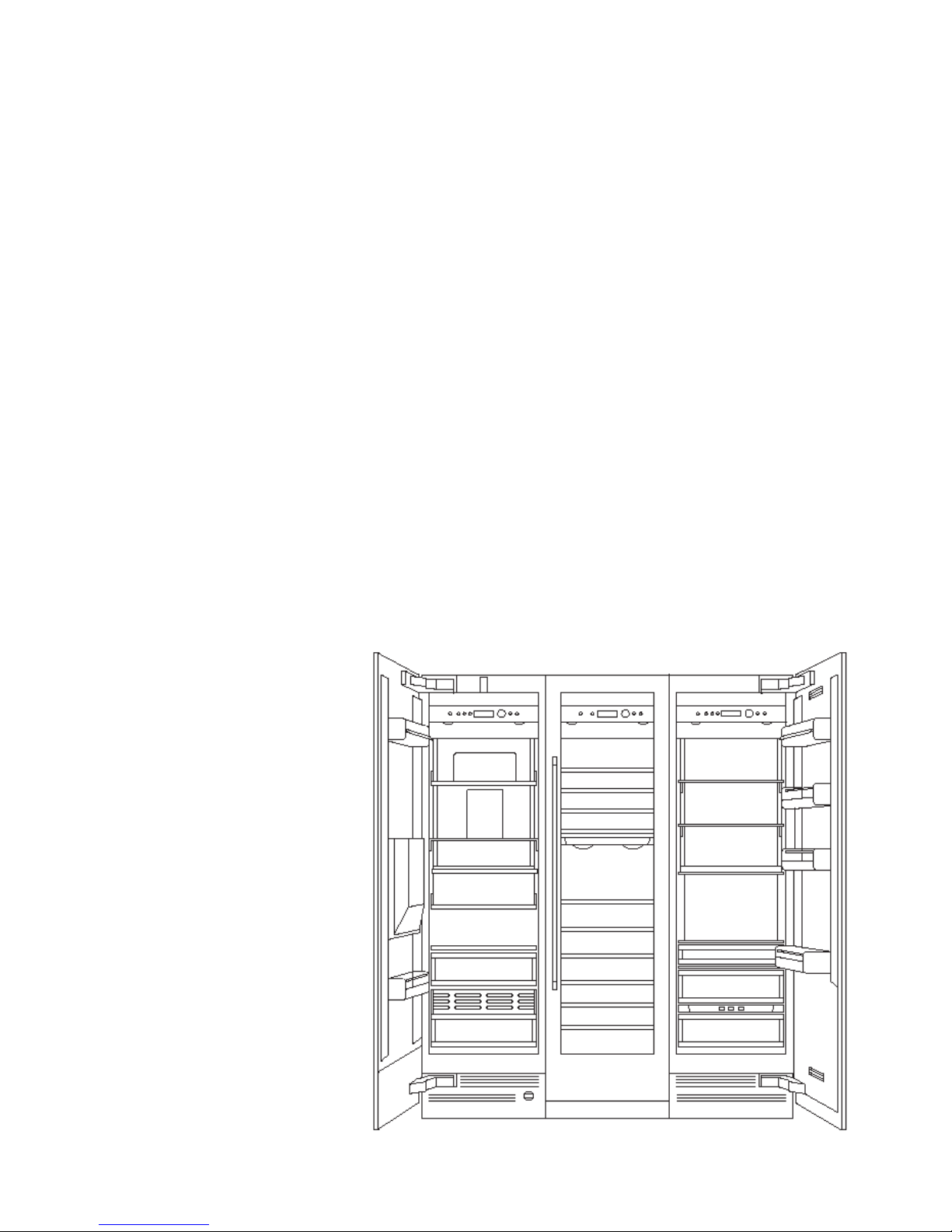
RW 4.4–260
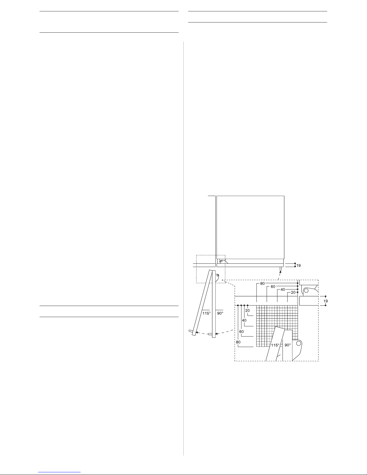
– Fully integrated appliances with
glass doors. Doors open to a
115 degree angle, so that trays can
be pulled out completely.
– Two separate temperature
zones, both continuously variable
from 5 °C to 18 °C. For perfect
storage conditions of red and white
wines, or for storing and tempering
both at the same time.
– Fully extendable trays in aluminium
and beech with optional presenter
to showcase valuable bottles and
an aluminium shelf for opened
bottles or decanters.
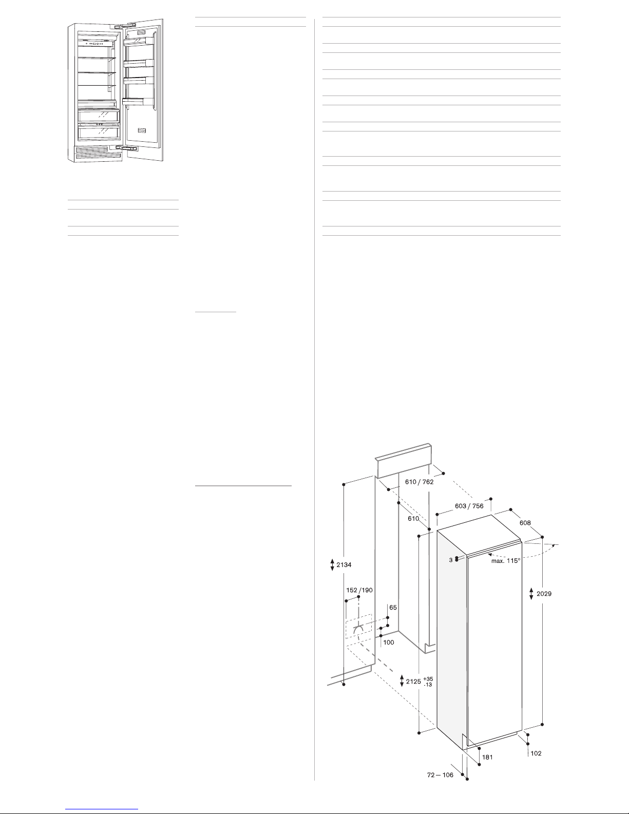
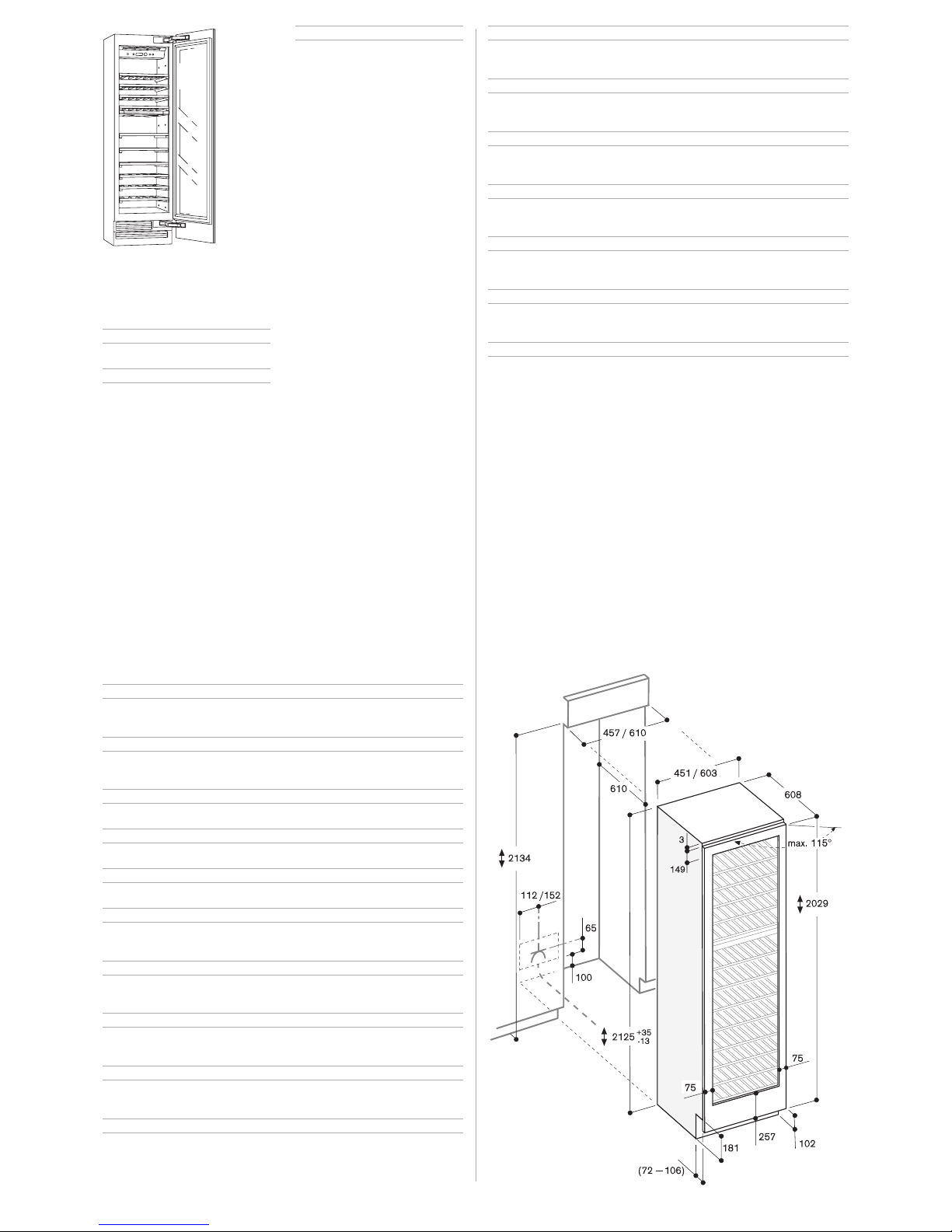
Niche height 213.4 cm.
Gross volume 296/422 litres.
Net volume 275/394 litres.
Capacity 70/101 bottles
(based on 0.75/l standard bottles)
Energy consumption
0.79/0.85 kWh/24 h.
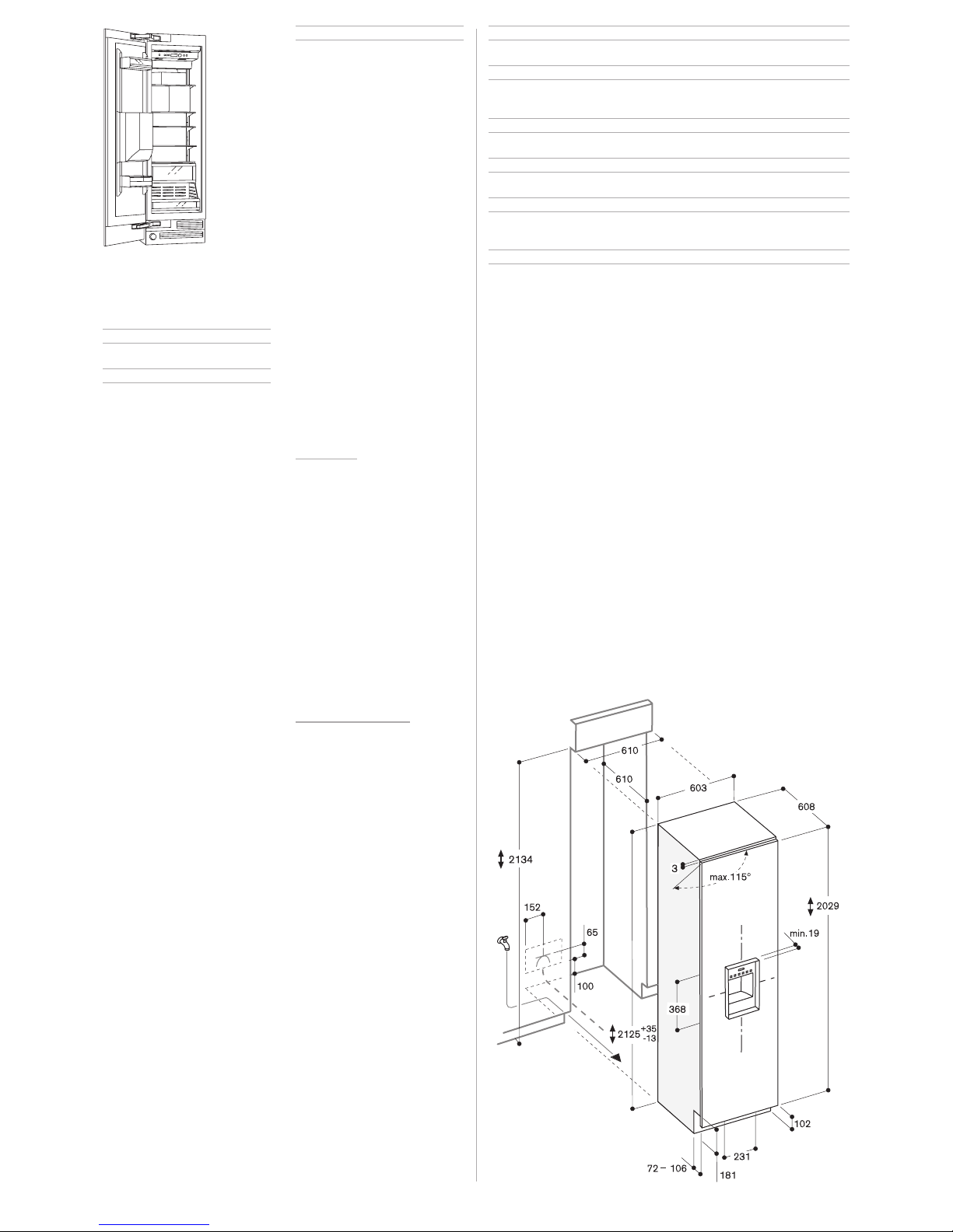
Electronic temperature control
with digital temperature display.
Dynamic cold air distribution.
Activated charcoal air filter.
Automatic defrosting with defrost
water evaporation.
Energy-saving vacation mode.
Open-door and malfunction
warning system.
Temperature adjustable from
+5 ° to +18 °C.
Two separate temperature zones,
both continuously variable.
Ten full extendable bottle trays in
beech and aluminium, up to four of
which can also store magnum bottles.
Interior lighting integrated in the
ceiling and the temperature
divider, can be switched on in the
lower temperature zone even when
the door is closed.
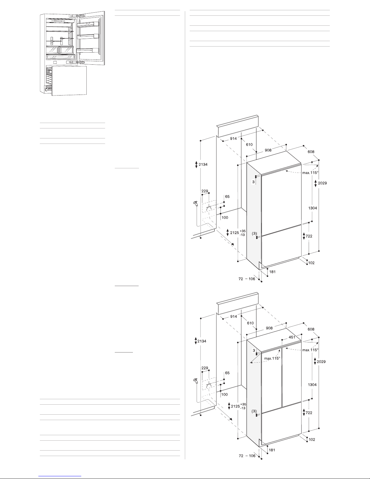
Planning note: Flat hinge.
Door hinge right, reversible.
The power socket can be planned
behind the appliance.
Rating: Total connected load 0.12/0.13 kW.
Connecting cable length 2 m with
plug.
Vario wine storage and temperature
control cabinet
with two temperature zones,
fully integrated
RW 414–260
Width 45.7 cm
RW 464–260
Width 61 cm
Special accessories: RA 491–131 Bottle tray in beech
and aluminium for RW 414, full
extendable.
RA 491–631 Bottle tray in beech
and aluminium for RW 464, full
extendable.
RA 493–030 Presenter
in aluminium (set of 3 for 3 bottles).
RA 492–130 Aluminium shelf
for RW 414, full extendable.
RA 492–630 Aluminium shelf
for RW 464.
RA 421–111 Stainless steel door
panel frame with handle for RW
414, left-hinged.
RA 421–112 Stainless steel door
panel frame with handle for RW
414, right-hinged.
RA 421–131 Aluminium door panel
frame with handle for RW 414,
left-hinged.
RA 421–132 Aluminium door panel
frame with handle for RW 414,
right-hinged.
RA 421–611 Stainless steel door
panel frame with handle for
RW 464, left-hinged.
RA 421–612 Stainless steel door
panel frame with handle for RW
464, right-hinged.
RA 421–631 Aluminium door panel
frame with handle for RW 464,
left-hinged.
RA 421–632 Aluminium door panel
frame with handle for RW 464,
right-hinged.
RA 461–112 Ventilation grille
Stainless steel, for RW 414,
right-hinged.
RA 461–113 Ventilation grille
Stainless steel, for RW 414,
left-hinged.
RA 461–612 Ventilation grille
Stainless steel, for RW 464,
right-hinged.
RA 461–613 Ventilation grille
Stainless steel, for RW 464,
left-hinged.