Minder Water Industries MINDERSPEED MXB User manual
MXB PUMP
INSTALLATION AND USER’S GUIDE
Table of Content:
1. Pump Overview
2. Installation
3. Initial start-up
4. Pump operation & maintenance
5. Disassembly/ Assembly procedure for seal replacement
6. Winterizing procedure
7. Troubleshooting
8. Replacement parts
a. MXB

IMPORTANT NOTICE
Attention Installer
This manual contains important information about the installation, operation and safe use of
this product. This information should be given to the owner/ operator of this equipment.
WARNING
Before installing, read and follow all warning notices and instructions accompanying this
filter/ pump. Failure to follow safety warnings and instructions can result in severe injury,
death, or property damage. Email sales@minderpool.com.au for additional free copies of
these instructions.
PUMP SAFETY INSTRUCTIONS
When installing and using this electrical equipment, basic safety precautions should
always be followed, including the following:
1. Read and follow all instructions.
2. Warning – To reduce risk of injury, do not permit children to use this product unless they
are closely supervised at all times.
3. WARNING – Risk of Electrical Shock. Connect only to a grounding type receptacle
protected by a ground-fault circuit-interrupter (GFCI). Contact a qualified electrician if
you cannot verify that the receptacle is protected by a GFCI.
4. Do not bury the electrical cord. Locate the cord to minimize the abuse from lawn
mowers, hedge trimmers, and other equipment.
5. WARNING – To reduce the risk of electrical shock, replace damaged cord immediately.
6. WARNING – To reduce the risk of electrical shock, do not use an extension cord to
connect unit to electric supply; provide a properly located outlet.
7. CAUTION – For continued protection against possible electrical shock, this unit is to be
mounted to the base in accordance with the installation instructions.
SAVE THESE INSTRUCTIONS!

Customer Service
Would you have further questions on Minder pump’s replacement spare parts, swimming
pool products, technical help, please email to sales@minderpool.com.au
Or contact your Minder’s Regional Sales Manager
Malaysia (9am to 6pm – UTC +8:00)
Website
Visit www.minderpool.com.au to find out information about Minder Products
Minder Water Industries
All rights reserved
This document is subject to change without notice
Trademarks and Disclaimers:
All Minder trademarks and logos are owned by Minder Water Industries Pty Ltd. Minder ©
trademarks and/or registered trademarks of Minder in Australia and/ or other countries.
Unless expressly noted, names and brands of the third parties that may be used in this
documents are not used to indicate an affiliation or endorsement between the owners of
these names and brands. Because we are continuously improving our products and services,
Minder reserves the right to change specifications without prior notice. Minder is an equal
opportunity employer.
The pump operates with Electrical voltage, and can generate both vacuum and pressure in
the water recirculation system. When properly wired and plumbed, this pump will operate in
a safe manner.
READ AND FOLLOW ALL SAFETY INSTRUCTION
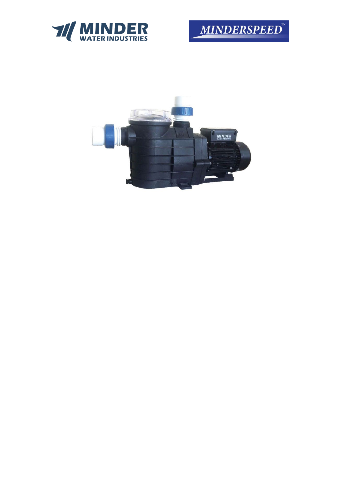
1. Pump Overview
Your recirculating pump is a centrifugal type pump to drive water flow to your water
recirculation system and is designed to operate for years with proper maintenance. The
pump wet-end case, diffuser, impeller are made from high quality thermoplastic materials.
These materials have been selected for their corrosion-resistant nature. When installed,
operated and maintained properly in accordance with these instructions, your pump will
provide years of service.
Your recirculating pump is driven by an electric motor. The motor is directly attached to the
pump impeller. The electric motor turns, it causes the impeller to turn and this causes the
water to flow. The water flows into the pump inlet (on the side) and through the strainer
basket to pre-filter large particles. The water flow then enters the center of the pump case
and through the impeller and out the pump discharge outlet port (above).
2. INSTALLATION
1. Check carton for any evidence of damage due to rough handling in shipment. If carton or
any pump components are damaged, notify Freight Carrier immediately.
2. After inspection, carefully remove pump from carton.
3. The pump should be secured to a flat solid foundation, high enough to prevent flooding
of the motor. A sheltered location is best, being sure to allow for adequate ventilation.
4. Provide space and lighting for routine maintenance access. Do not mount electrical
controls directly over pump.
5. The pump should be installed as near to the pool and spa as practical. Avoid installing
the pump more than a few feet above the water level. Suction lifts of more than five (1.5
meter) feet will cause very long priming times. Pump will not lift more than 2 meter.
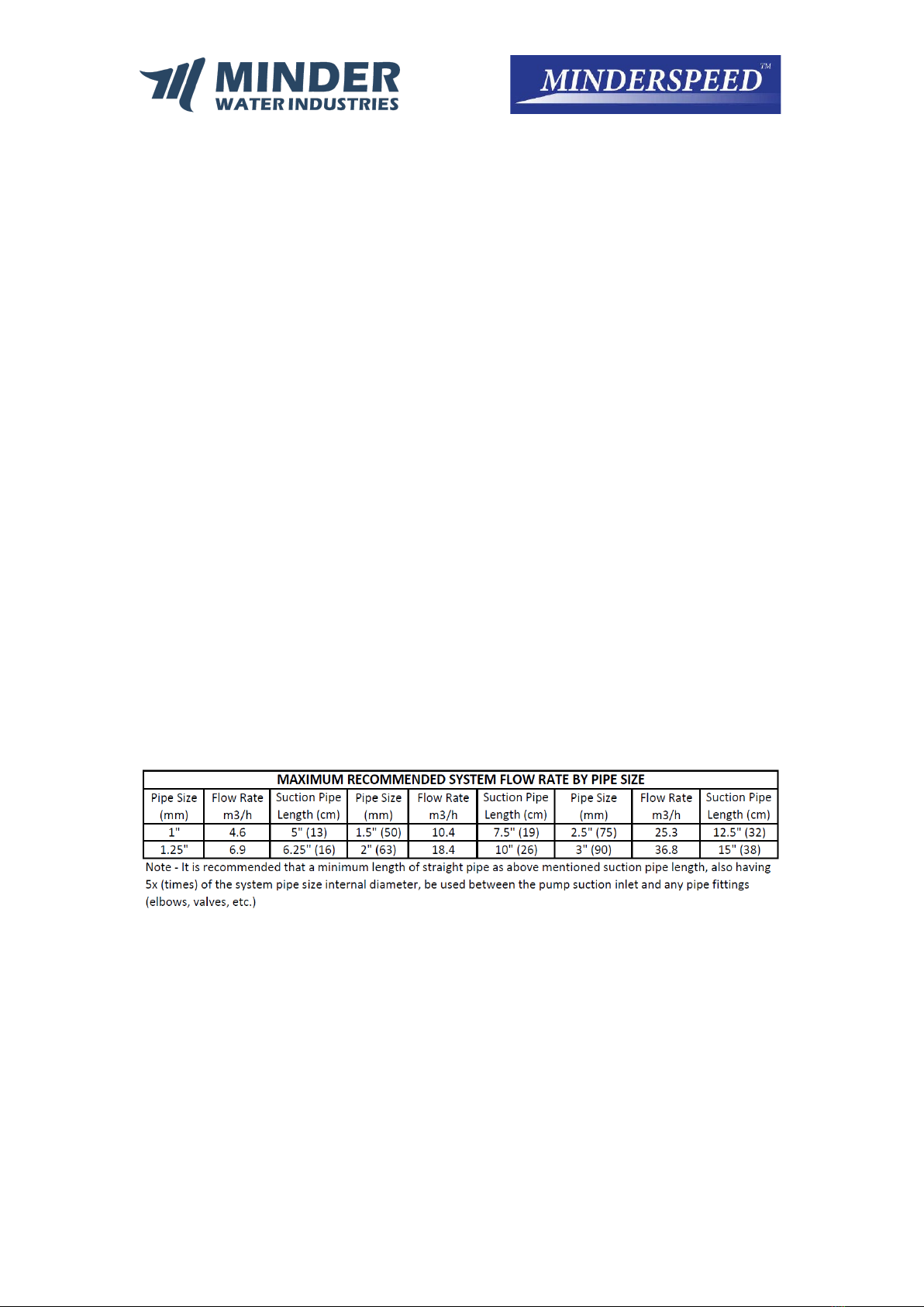
Pipe Sizing
6. The location should provide for adequate floor drainage to prevent flooding.
7. Provide for the need to remove the pump for potential service by providing valves or
other means to disconnect the pump suction and discharge.
8. Never store pool chemicals within 10ft of your pool filter and pump. Pool chemicals are
corrosive and should always be stored in a cool, dry, well-ventilated area.
9. For below water installations ensure isolation valves are installed to reduce risk of
flooding or water impact.
10. For above water installation ensure check valves are installed to prevent negative
pressure (vacuum) in filter which may damage filter tank. (This applies to M series filter
which is without air relief valve feature to relieve negative pressure)

WARNING
Chemical fumes and/or spills can cause severe corrosive attack to the filter and pump
structural components. Structurally weakened the filter or pump components can cause
filter, pump or valve attachments to separate and could cause severe bodily injury or
property damage.
11. Assemble piping and pipe fittings to pump and valve with Minder provided Unions with
pipe glue. All piping must conform to local and state plumbing and sanitary codes.
Note: It is highly recommended to use Minder’s provided unions to avoid forceful
installation that may cause damage to pump main body. Damage to pump main body is a
costly mistake compare to damage to unions.
12. Use thread seal tape or pipe sealants on all male connections of pipe and fittings. Use
only pipe sealant compounds suited for plastic pipe. Support pipe to prevent strains on
filter, pump or valve. DO NOT USE PETROLEUM BASE PRODUCTS.
13. Avoid over tightening the pipe threads when connecting fittings to the pump. Proper
procedure is to apply a pipe sealant to the thread and then install hand tight plus 1-1/2
turns. DO NOT OVER TIGHTEN.
14. Long piping runs and elbows restrict flow. For best efficiency, use the fewest possible
fittings, large diameter pipe (at least 1-1/2”) and locate equipment as close to the pool
as possible. The pump suction line should not be smaller than the pipe size on the inlet
of the pump.
15. It is essential that the suction line be free of air leaks and air traps.
16. For commercial pump MRB and MTX series, please make sure gate valves and shock
absorbers be installed at suction and discharge port to overcome water hammer effects.
WARNING
Blockage of suction fittings can cause severe or fatal injury due to drowning. Small children
using pool/spa equipment must always have close adult supervision.
To reduce the risk of injury, do not permit children to use this product unless they are
closely supervised at all times.
17. Wiring of this pump should be performed by a licensed electrician in accordance with
your local electrical code.
WARNING - Never work on pump while it is running or power is still connected; hazardous
voltage can cause severe or fatal injury. A suitable ground fault interrupter should always
be installed at the power supply source of the unit.
Ground motor before connecting to electrical power supply. Failure to ground motor can
cause severe or fatal electrical shock hazard. Do not ground to a gas supply line.
18. The pump motor must be wired for the proper voltage in accordance with the wiring
diagram supplied with the motor.
Wiring the motor with the incorrect supply voltage will cause damage to the motor and
void the warranty.

19. The wiring to the motor should be kept as short as possible and large enough NOT to
cause an excessive voltage drop. Use the wire size table as a guide in selecting minimum
conductor size.
20. Install, ground and bond wire according to local code requirement.
For direct wiring into main supply, Minder pump is supplied with a power cord that can be
plugged into the power source. There are two terminals labelled as AC-L and AC-N. Attach
the power leads to these terminals. Either wire may be attached to either terminal (see
Figure 1).
Procedure:
1. Make sure that the pump is disconnected from power source.
2. Unscrew the control panel located on the top of the electric motor. The power
connection is located at the side where the wire comes out of the box.
3. Unscrew the pin that fastened the power cord.
4. Take out the power cord with plug and replace with the new one.
5. To fasten the power cord, connect the live wire to the AC-L pun and the neutral wire
to the AC-N pin. The ground wire should connect to the ground wire pin.
6. Connect power to ensure the connections are correct. If not, repeat the steps above
and check both pin connections.
7. Recover
3. INITIAL START-UP:
1. Release all system pressure and open all air bleeders on total hydraulic system prior to
starting the pump. See filter owner’s manual.
2. Ensure that all fittings, clamps, closures and couplings are tight and in accordance with
equipment manufacturer’s recommendations.
3. Open suction and discharge valving to allow free flow of water. On flooded suction
pumps with strainer pot, the water source is higher than the pump, the water will flow
into the pump strainer compartment and the compartment will fill with water.
4. On non-flooded suction systems, the pump lid will have to be removed by rotation the
lid counter-clockwise to a stop and lifting the lid.
5. The pump strainer compartment should be filled with water up to suction opening on
the pump.
6. It is good practice to lubricate the lid O-ring with silicone lubricant each time the lid is
removed. The O-ring should be cleaned and inspected every time the strainer pot is
opened.
7. The lid should be replaced on the compartment by aligning the lid ears with the slots on
the strainer compartment. Press the lid down and twist the lid clockwise to engage the
lid.
8. The pump is now ready to prime. Energize the motor and the pump will prime. The time
to prime will depend on the suction lift and the distance and size of the suction piping.
Turn off power if the pump does not prime within five minutes and refer to
Troubleshooting Guide section of this manual.
NOTICE: Never run the pump dry. Running dry may damage the seals and pump housing.
This could allow water leakage and flooding.

4. Pump Operation & Maintenance
The strainer basket in the pump should be inspected and cleaned twice each week. Remove
the clear lid and the basket and clean debris from basket. Inspect the lid O-ring; if damaged
replace. The pump seal requires no lubrication. Refer to motor service centers for motor
servicing.
Disassembly/ Assembly Procedure for Seal Replacement:
WARNING: Never work on pump while it is running or power is still connected. Hazardous
voltage can cause severe or fatal injury.
1. Stop pump and release system pressure
2. Disconnect motor power at circuit breaker
3. Close suction and discharge gate valves
4. Use extreme care when handling the mechanical seal. The mating seal surfaces are
polished and are easily damaged.
5. The mechanical seal can be changed without disconnecting piping by removing 6
bolts and pulling the motor with pump bracket diffuser and impeller assembly away
from front pump housing body.
6. Remove impeller and rotating portion of seal by holding motor shaft and rotating
the impeller counter-clockwise when facing the shaft extension on the motor.
7. The rotating portion of the seal can now be removed from the impeller. Clean the
impeller hub and lubricate with soapy water. Wipe off shining carbon sealing surface
of new mechanical seal with a clean tissue to remove oily fingerprints or other
foreign materials. The new rotating seal can be pressed back onto the impeller.
8. To remove the stationary ceramic seal seat, first loosen the four motor bolts which
run through the entire length of the motor into the bracket diffuser. Remove the
bracket diffuser from the motor. Press the ceramic seat and rubber gasket out of the
bracket diffuser.
9. Clean the bracket diffuser seal area and lubricate with soapy water. Press the new
ceramic seal and gasket into the bracket diffuser, being sure it is fully seated. Wipe
off the ceramic sealing surface with a clean tissue to remove oily fingerprints or
foreign substances.
10. Place the bracket diffuser on the motor and carefully align the four motor through
bolts. Secure the housing onto the motor being careful not to over-tighten the bolts.
Gradually bring bolts up to final tightness by moving across diametrically and in a
criss-cross pattern.
11. Screw the impeller with new rotating seal onto the motor shaft. Rotate the motor
shaft to make sure the impeller is not touching the bracket diffuser.
12. Clean the bracket diffuser o-ring and check to make sure it is in position. Replace the
motor and bracket diffuser on the front pump housing body and bolt into position
with 6 bolts. Gradually bring bolts up to final tightness by moving across
diametrically and in a criss-cross pattern.
13. Refer to initial start-up procedures to restart the pump.

5. WINTERIZING
NOTICE: Allowing the water to freeze in pump will damage the pump and cause potential
water damage/ flooding and potential property damage.
1. Drain all water from pump housing and piping when freezing temperatures are
expected. A drain plug is provided to drain the pump. If the pump has a strainer pot,
both the strainer drain plug and the housing drain plug should be removed. If pump
has no strainer pot, then only remove the housing plug.
2. If the pump can be removed and placed in an inside dry location this should be
done.
3. For an outdoor unprotected location, it is best to protect the equipment in a
weatherproof enclosure.
4. Do not wrap the motor with plastic because condensation could form inside the
motor.
5. In installation where the pump cannot be drained, a 40% propylene glycol 60%
water solution will protect to -50° F.
NOTICE: Do not use anti-freeze solutions except propylene glycol; as other anti-freeze is
highly toxic and will damage the pump.

6. TROUBLESHOOTING
Problem
Cause
Solution
Pump will not prime
1. No water in strainer
compartment
2. Strainer compartment lid is not
tight
3. Damaged lid o-ring (air
leakage)
4. Water level is below skimmer
(for Skimmer type pool)
5. Clogging in the piping system
before the pump suction
6. Closed valve in piping system
7. Pump speed too low (for
multispeed pump)
8. Air leak in suction line.
•Add water to strainer
compartment
•Tighten lid
•Replace lid o-ring
•Adjust pool water level
•Clear basket
•Check all valves and
open all necessary
valves
•Adjust to maximum
speed (for multispeed
pump)
•Find & fix leak
Low Flow-High Filter
Pressure
1. Filter is dirty.
2. Restriction in return line.
•Clean filter.
•Open return line
restriction.
Low Flow-Low Filter
Pressure
1. Strainer basket or skimmer
basket is clogged. 2. Clogged
impeller.
3. Air leak in suction line.
4. Restriction in suction line.
•Clean basket.
•Clean obstruction.
•Find & fix leak.
•Find and open
restriction.
Motor does not turn
1. Power switch is off.
2. Circuit breaker has tripped.
3. Pump is in "Off-mode" on a
timer controlled circuit.
4. Motor terminal connections are
incorrect.
5. Motor shaft is locked by bad
bearing.
6. Impeller is locked by debris.
7. Fuses blown or thermal overload
open
Motor windings burnt out
Defective motor starting switch
Insufficient voltage
•Check power switch &
reset.
•Check circuit breaker &
reset, if re-trips, contact
electrician.
•Check timer mode.
•Have terminal
connections checked by
electrician.
•Have motor bearings
replaced or replace
pump.
•Have fuse or thermal
overload replaced or
replace pump.
•Have motor replaced
Motor Over-Heating
1. Electrical supply connections are
incorrect.
2. Wiring to pump is undersized.
3. Power Company supply voltage
is low.
4. Ventilation is inadequate for
motor.
•Have terminal
connections checked by
electrician.
•Consult electrician to
rewire pump.
•Notify Power Company.
•Remove any restrictions
to air flow.

Correct Disposal of this Product
This marking indicates that this product should not be disposed with other household
wastes throughout the EU. To prevent possible harm to the environment or human
health from uncontrolled waste disposal, recycle it responsibly to promote the
sustainable reuse of material resources. To return your used device, please use the
return and collection systems or contact the retailer where the product was purchased.
They can take this product for environmental safe recycling.
7. Replacement Spare parts
Table of contents
Popular Water Pump manuals by other brands

EBARA
EBARA ESA200W instruction manual

Dover
Dover PSG ALL-FLO A075 Installation, Operation & Maintenance Instruction Manual

EBARA
EBARA EVMS 1 Operating and maintenance manual

Grundfos
Grundfos BMS hs Assembly, installation and operating instructions

FLOJET
FLOJET G573 installation guide

Wilo
Wilo HiSewlift 3 Series Installation and operating instructions


vacuubrand
vacuubrand ME 4C NT VARIO Instructions for use

Grundfos
Grundfos COMFORT PM instructions

salmson
salmson SBS 2-204 Installation and starting instructions

Boulton Pumps
Boulton Pumps ESK Series Instruction for operation and maintenance

Forester
Forester FSP-650 instruction manual

Hayward
Hayward Super Pump VS 700 owner's manual