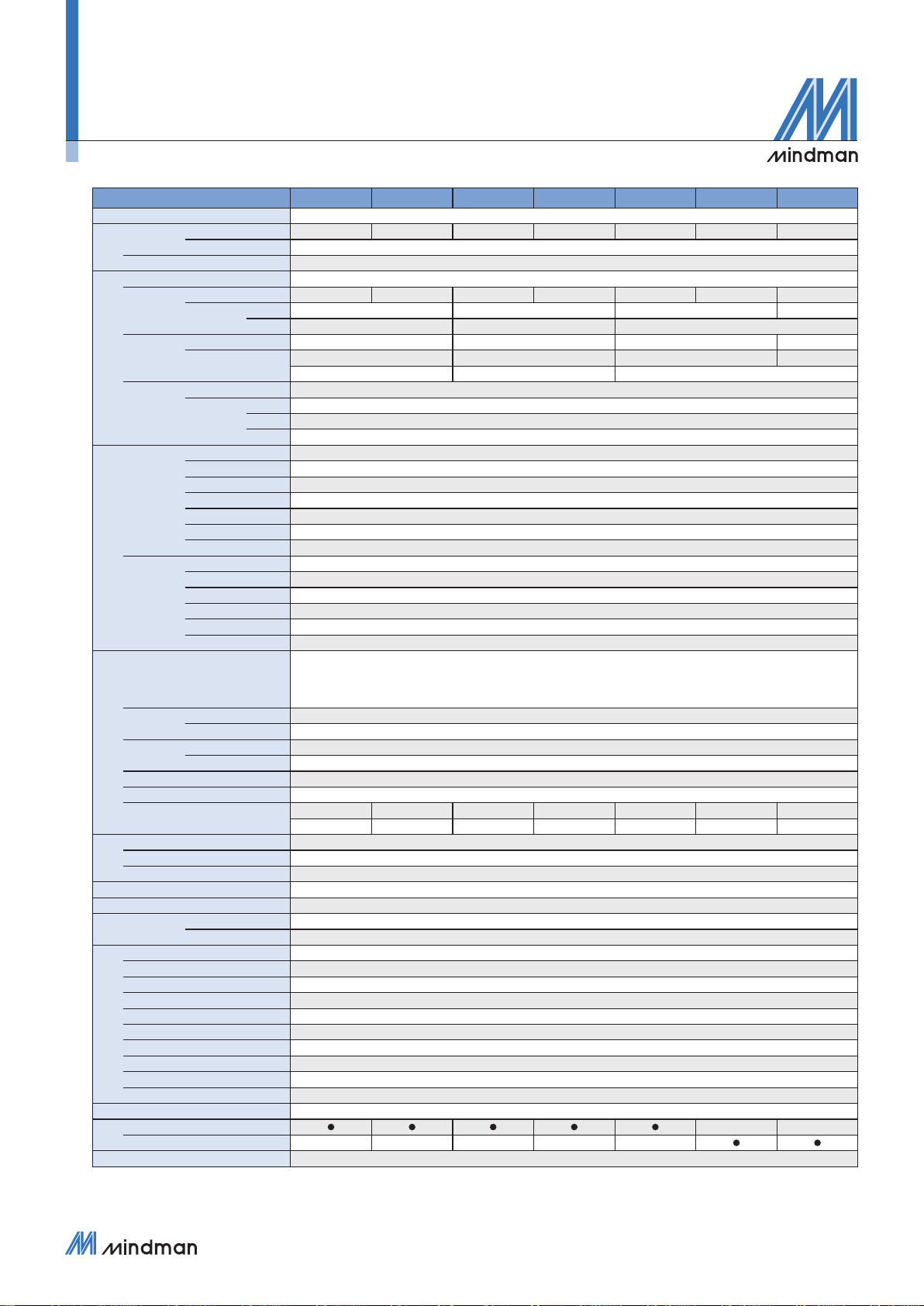
6
Model 005 010 050 100 500 101 201
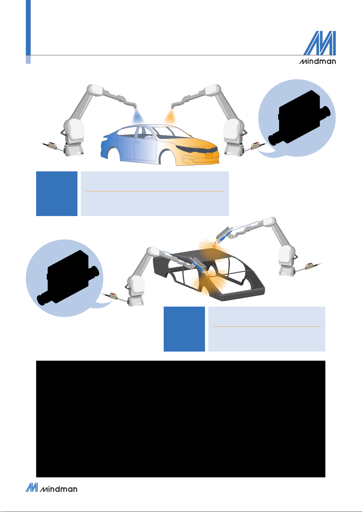
Fluid Dry air, N2, Non-corrosive / Non-ammable gas
Sensor
element
Flow
Measured ow rate range
0 ~ 500 mL/min 0 ~ 1000 mL/min 0 ~ 5 L/min 0 ~ 10 L/min 0 ~ 50 L/min 0 ~ 100 L/min 0 ~ 200 L/min
Flow direction Unidirection
Pressure Rated pressure range -90 ~ 800 kPa
Display
Display 4 digital × 4 digital, 7 segment LCD display ( Red / Green / Orange )
Instant ow
rate
Display range 0 ~ 525 mL/min 0 ~ 1050 mL/min 0 ~ 5.25 L/min 0 ~ 10.50 L/min 0 ~ 52.5 L/min 0 ~ 105.0 L/min 0 ~ 210 L/min
Min. setting
scale
LPM 1 mL/min 0.01 L/min 0.1 L/min 1 L/min
CFM *1 0.01 ft3/min 0.1 ft3/min 1 ft3/min
Accumulated
Flow
Display range 99999999 mL 999999.99 L 9999999.9 L 99999999 L
Min. Setting Scale *1 1 mL 0.01 L 0.1 L 1 L
0.01 ft30.1 ft31 ft3
Pressure
Display
Display range -100 ~ 1000 kPa
Min. Setting
Scale
kPa 1
kgf/cm20.01
bar / psi 0.01 / 0.1
Accuracy
Flow
Guaranteed range 2 ~ 100 % F.S.
Indicator accuracy ± 3 % F.S. ± 1 digit *2
Analog output accuracy ± 5 % F.S. *2
Repeatability ± 1 % F.S. ± 1 digit *3
Linearity ± 3 % F.S. *3
Temp. characteristic ± 2 % F.S. ( 15 ~ 35 °C ) ; ± 5 % F.S. ( 0 ~ 15 °C, 35~ 50 °C ) ( compare with *3 )
Pressure characteristic ± 5 % F.S. ± 1 digit *4
Pressure
Guaranteed range 0 ~ 100 % F.S.
Indicator accuracy ± 2 % F.S. ± 1 digit *5
Analog output accuracy ± 2.5 % F.S. *5
Repeatability ± 0.2 % F.S. ± 1 digit *5
Linearity ± 1 % F.S. *5
Temp. characteristic ± 2 % F.S. ( compare with *5 )
Switch output
Switch output
2 NPN : open collector 2 outputs
Max. Load Current : 125 mA
Max. Supply Voltage : 28 V DC
Voltage Drop : ≤ 1.5 V
2 PNP : open collector 2 outputs
Max. Load Current : 125 mA
Max. Supply Voltage : 24 V DC
Voltage Drop : ≤ 1.5 V
Response
time
Flow 800 ms ( 50 ms, 80 ms, 120 ms, 200 ms, 400 ms, 1500 ms selectable )
Pressure 2.5 ms ( 25 ms, 100 ms, 250 ms, 500 ms, 1000 ms, 1500 ms selectable )
Output
mode
Flow Hysteresis Mode, Window Comparator Mode, Accumulated Output, Accumulated Pulse Output
Pressure One Point Set Mode, Hysteresis Mode, Window Comparator Mode
Hysteresis Adjustable
Output short circuit proterction Yes
Accumulated pulse output *1 5 mL/Pulse 10 mL/Pulse 0.05 L/Pulse 0.1 L/Pulse 0.5 L/Pulse 1 L/Pulse 2 L/Pulse
0.02 ft3/Pulse 0.04 ft3/Pulse 0.2 ft3/Pulse 0.4 ft3/Pulse 2 ft3/Pulse 4 ft3/Pulse 7 ft3/Pulse
Analog
output
Voltage output Voltage output range : 1 ~ 5 V *6 ; Output impedance : 1 KΩ
Current output Current output range : 4 ~ 20 mA *6 ; Load impedance : ≤ 300 Ω
Response time Pressure : ≤ 50 ms ; Flow : ≤ 100 ms
External input Non-voltage input, < 0.4 V, ≥ 30 ms
Communication interface RS-485 *7
Power Power supply voltage 12 ~ 24 V DC ± 10 %, Ripple ( P-P ) ≤ 10 %
Current consumption ≤ 50 mA
Environment
Withstand Pressure 1000 kPa
Enclosure IP40
Working Fluid Temp. 0 ~ 50 °C ( No condensation or freezing )
Ambient Temp. Range Operation : 0 ~ 50 °C ; Storage : -10 ~ 60 °C ( No condensation or freezing )
Ambient Humidity Range Operation / Storage : 35 ~ 85 % R.H. ( No condensation )
Insulation Resistance ≥ 50 MΩ ( 500 V DC, between case and lead wire )
Withstand Voltage 1000 V AC in 1-min ( between case and lead wire )
Vibration Total amplitude 1.5 mm or 10 G, 10 Hz ~ 55 Hz ~ 10 Hz scan for 1 minute, 2 hours each direction of X, Y and Z
Shock 100 m/s² ( 10 G ), 3 times each in direction of X, Y and Z
EMC IEC 61000-6-2, IEC 61000-6-4
Lead wire ø4 Oil-resistance cable ( PVC ) - 26 AWG ( 0.15 mm2 ) - 6 cores
Port
Size
R6, F1C
R8, F4C
Weight (with 2 meter lead wire)
Approx. 109.3 g ( ø6 port ) ; Approx. 112.7 g ( ø8 port ) ; Approx. 118 g ( Rc1/4" port ) ; Approx. 128.5 g ( Rc1/8" port )
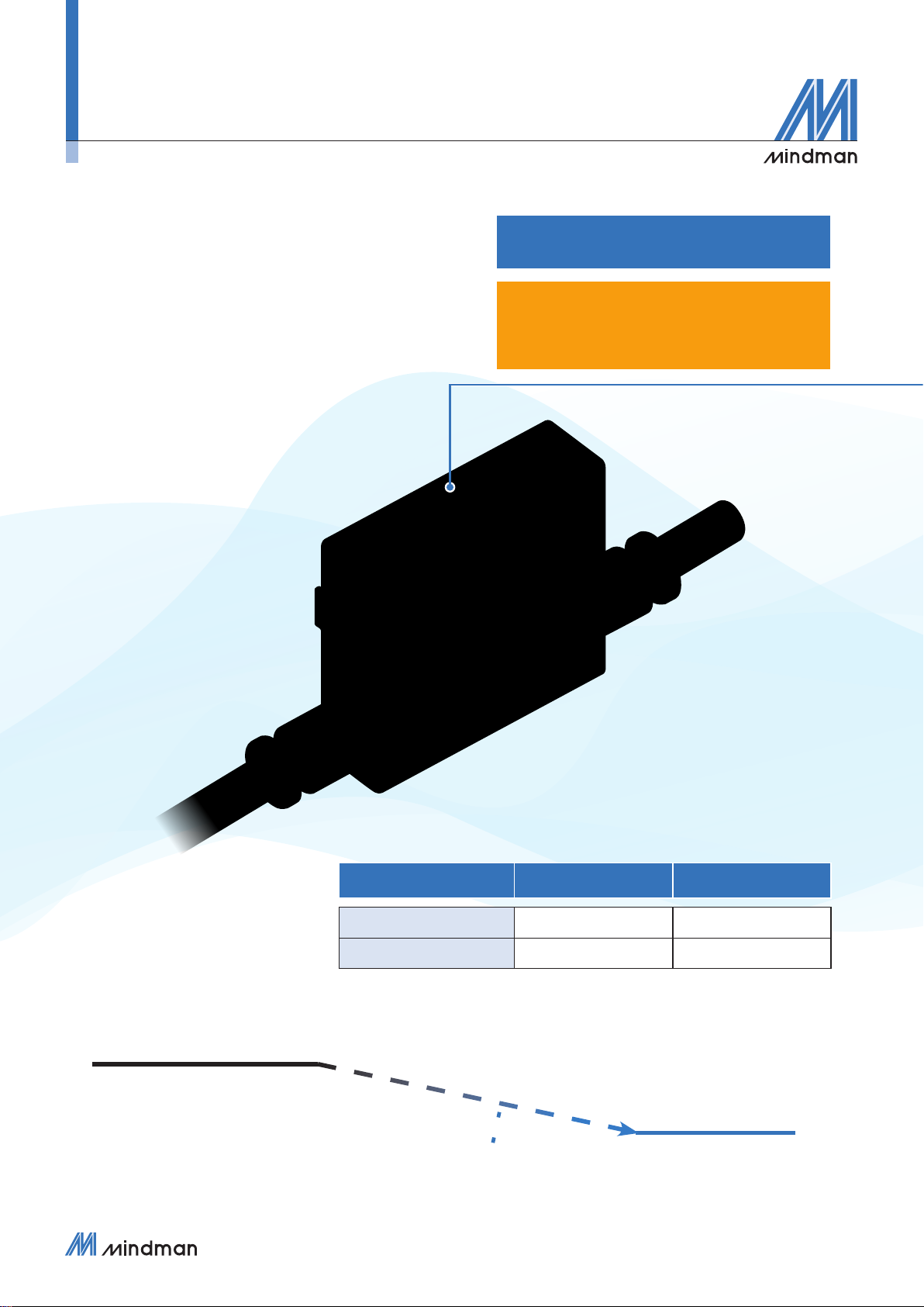
FLOW & PRESSURE SENSOR ( INSTRUCTION MANUAL )
MFP01 Specications
*1. CFM ( ft3/min*10-2 ) and ft3*10-2
*2. Condition: Inlet pressure: 300 kPa , Outlet pressure: 1 atmospheric pressure, 25 °C
*3. Condition: Outlet pressure: 1 atmospheric pressure, 25 °C
*4. -90 ~ 800 kPa, Outlet pressure: 1 atmospheric pressure, 25 °C
*5. Outlet ow rate = 0 L/min, 25 °C
*6. PWM output, corresponding to pressure sensor 0 ~ 1000 kPa
*7. This function only available for Output Specication -02 and -04