II
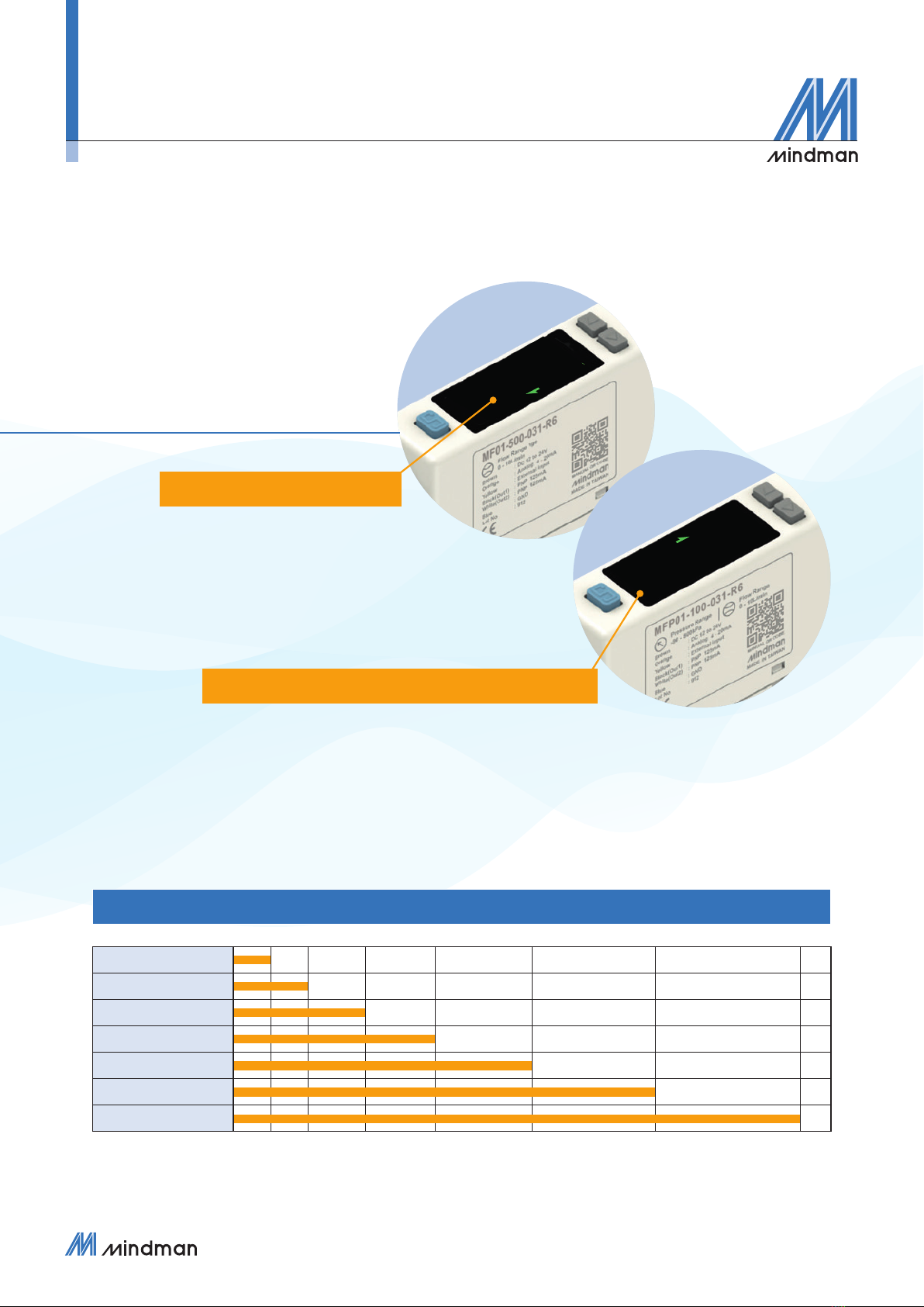
DIGITAL FLOW SENSOR ( INSTRUCTION MANUAL )
MF01 Contents
Product features..................................................................................................................................................................... 1
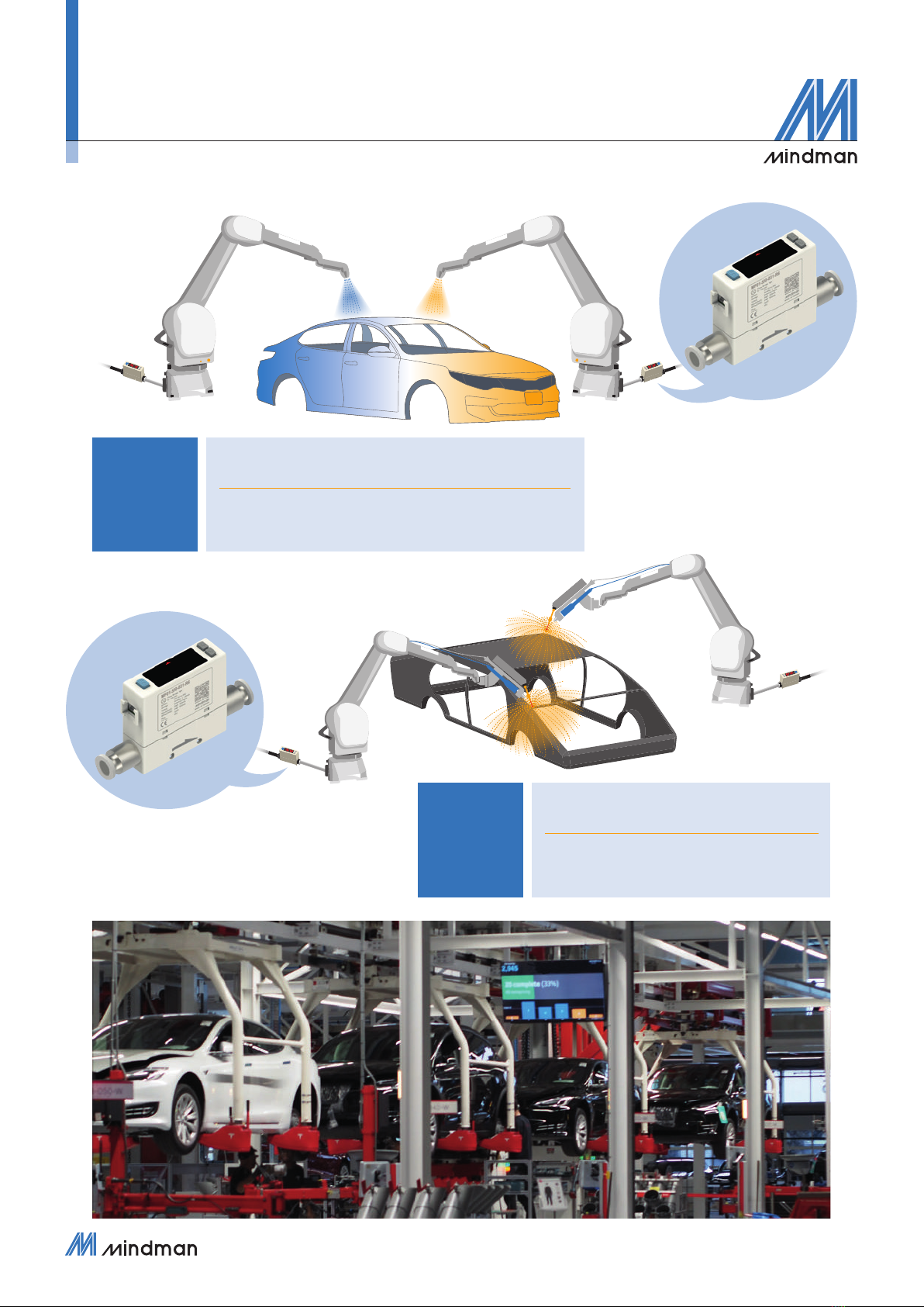
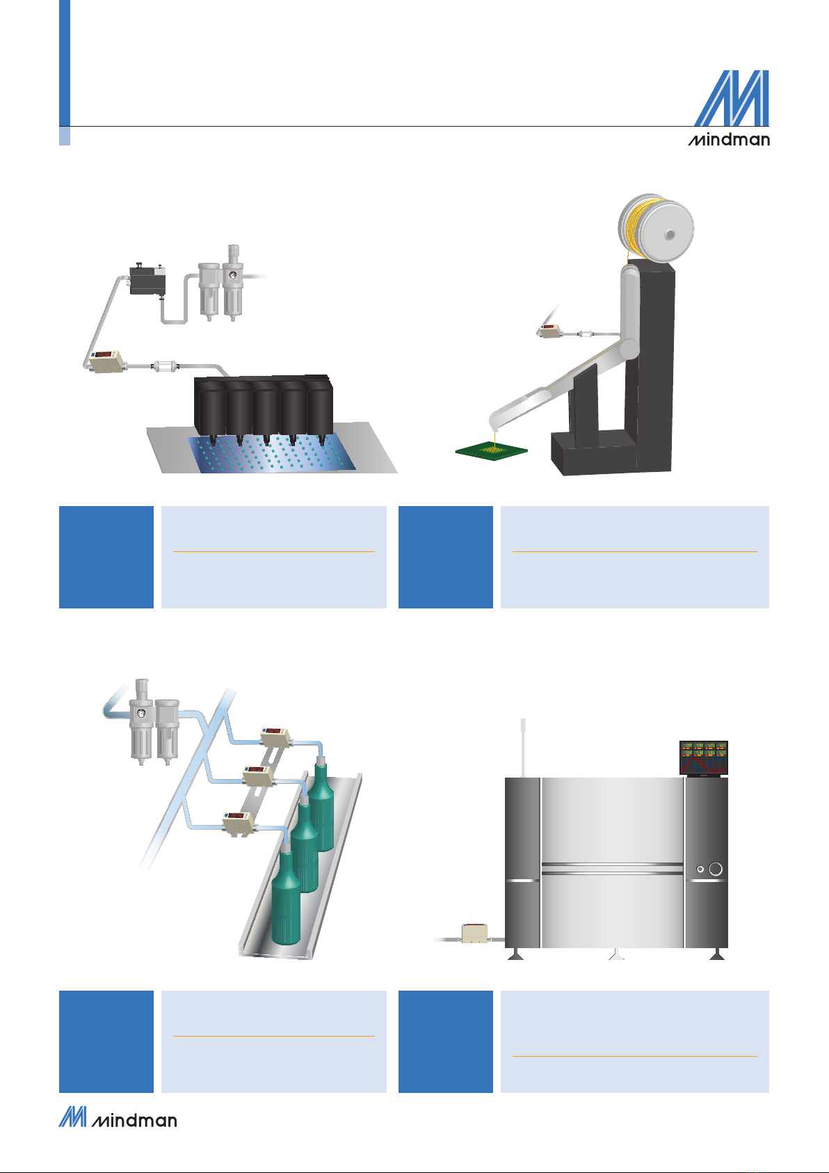
Application..................................................................................................................................................................................3
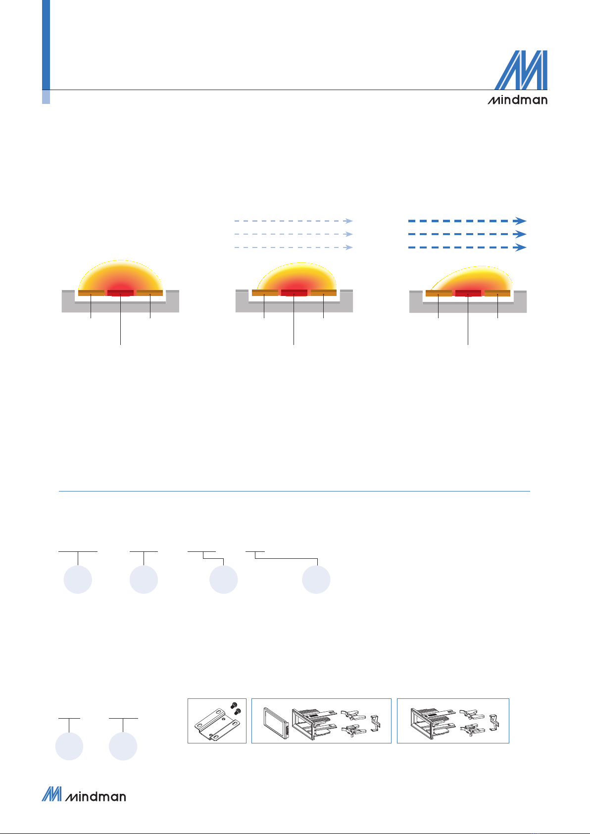
Thermal mass ow sensor principles.................................................................................................................4
Order example..........................................................................................................................................................................4
Specications...........................................................................................................................................................................5
Output type .................................................................................................................................................................................7
Pressure loss characteristics.....................................................................................................................................8
Installation instructions................................................................................................................................................... 9
● Piping ..................................................................................................................................................................................................9
● Mounting bracket.................................................................................................................................................................................9
● Wiring diagrams ................................................................................................................................................................................10
● Dimensions........................................................................................................................................................................................ 11
● Mounting accessories........................................................................................................................................................................12
How to use.................................................................................................................................................................................13
● Names and functions of individual parts ...........................................................................................................................................13
● Internal structure ...............................................................................................................................................................................14
● Functions instructions........................................................................................................................................................................15
Functions setting mode .................................................................................................................................................................15
Measurement mode ......................................................................................................................................................................16
● Operation setting instructions............................................................................................................................................................17
[F-01] OUT1 setting selection .......................................................................................................................................................17
[F-02] OUT2 setting selection .......................................................................................................................................................18
[F-03] LCD display color selection ................................................................................................................................................19
[F-04] Response time selection.....................................................................................................................................................19
[F-05] Display refresh time selection............................................................................................................................................. 20
[F-06] Unit selection ......................................................................................................................................................................20
[F-07] Flow reference standard selection...................................................................................................................................... 20
[F-08] Display rotation ...................................................................................................................................................................20
[F-09] Accumulated value hold selection.......................................................................................................................................21
[F-10] Flow sensor display mode selection ...................................................................................................................................21
[F-91] Power-save mode selection................................................................................................................................................ 22
[F-92] External input selection.......................................................................................................................................................22
[F-93] Modbus RTU setting ...........................................................................................................................................................23
[F-94] Fine adjustment setting.......................................................................................................................................................24
[F-95] Forced output function ........................................................................................................................................................24
[F-99] Reset to the default setting .................................................................................................................................................25
Instantaneous ow zero adjustment function ................................................................................................................................25
Reset accumulated ow function ..................................................................................................................................................25
Peak value display ........................................................................................................................................................................25
Bottom value display .....................................................................................................................................................................26
Key lock / Unlock mode.................................................................................................................................................................26
Modbus RTU instruction...............................................................................................................................................26
Error code instruction.....................................................................................................................................................28
Caution for safety................................................................................................................................................................ 29