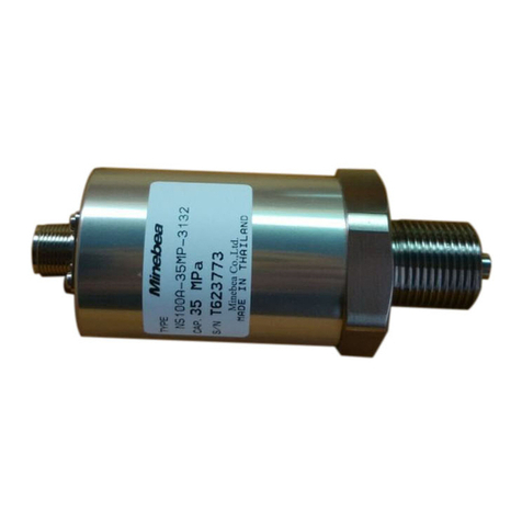
Minebea TWOFB-NM Series User manual

KT60443-1A
Read this operation manual thoroughly prior to start use of this product.
Be sure to observe the notes and cautions mentioned in this text of operation manual.
You will please file this manual in such a way that it is available anytime immediately whenever
you want to refar to.
The following are the marks and bymbols used in this operation manual. The following are the marks and
symbols for the matters which you must not do absolutely or to which you must pay full attention or you
must refer to. Be sure to peruse the paragraphs marked with these marks and symbols.
CAUTSION If not observed , it will cause troubles of injury or damage done to
properties or result in endangering a human life.
DO NOT DO THE MATTERS MAKED WITH THIS MARK ABSOLUTELY.
This mark shows the limitation or attension which you must pay when
operating or working . Be sure to read thoroughly in order to avoid
making a mistake in operational procedure.
1. Preface
Thank you very much for your purchase of our product MINEBEA TYPE TORQUE TRANSDUCER .
First of all , you will please check whether or not there is any damage done to the transducer
in transit or the model of the unit delivered is as specified in the order sheet .
If there are any doubtful or unkonwn points , be sure to contact the dealer or our sales office .
Refar to the catalogues or specifications for the specification of related models .
2. Outline
This is a torque transducer having the thin type flange /bearingless construction combining
an optical transformer of the optical transmission system taking out signals without
contacting from a rotary body with the torque detecting flanges that a strain gauge has
been stuck and calibrated . Use of this torque transducer makes it possible to make
measurement of both static and dynamic torques . This torque transducers are characerized
by high accuracy , high rigidity , improvement of fatigue proofness and long term stability etc .
The division construction of the stator ( antenna ) has simplified the fitting and removal of it .
OPEREATION MANUAL
(TORQUE TRANSDUCER TMOFB-*NM)
MINEBEA CO.,LTD.MEASURING COMPONENTS BUSINESS UNIT
1

KT60443-1A
・ Be sure to use this unit within the range of rated capacities .
・ Be sure not to apply a voltage exceeding the maximum allowble applying
voltage .
・ Fit this unit , using hexagonal bolts (holed ) The size of bolts to be used
is mentioned in this text of operation manual as well as specfication .
Selection of bolts shall be made in accordance with
STRENGTH DIVISION 10.9 OR HIGHER OF JIS B 1051 .
・ In the environment where screws and bolts tend to loosen easily ,
retighten them periodically or provide a detent thereto .
・ In case this unit is fitted to medical treatment apparatuses or machines
influencing human life , be sure to provide a protective circuit in preparation
for the failure of function of this unit .
・ In case this unit is used under special enviromental conditions , be sure to
consult with us before use .
3. Fitting method
3-1 . An example of fitting
① ② ③ ④ ⑤
① DY ( Dynamo )
② Torque transducer TMOFB-*NM
③ Coupl
i
( H flange )
④ Flexible coupling
⑤ Intermediate bearing
CAUTION
MINEBEA CO.,LTD.MEASURING COMPONENTS BUSINESS UNIT
2

KT60443-1A
3-2 . Order of fitting
(1) Fit a roller on a rotating axis
Before fitting , be sure to wipe off anticorrosive agent coated on the flanges and spigot
joint with such solvents as ethanol etc . Prevent dust or foreigh matter from sticking on the
fitting surface .
With the spigot joint at rotor as a guide , fix it with M12(5KNM:M14) hexagonal holed bolts .
(Refer to Fig . 1 )
Refer to the separate table of tightening torques for the details of tightening torques .
At the time of fitting , full care must be taken to prevent damage from being done to the
transmitting coil ( bakelite bobbin ) located at the outer circumference of the rotor .
After fitting , remove the green tape protecting a luminous element .
FIG.1
(2) Dividing the stator ( antenna ) , install it by adjusting it to the rotor . Disconnecting 6-M6
hex holed bolts illustrated in Fig . A of fIg . 2 , divide the antenna . When disconnecting
be sure not to lose set bolts , counter-sunk spring washers accidentally . As for the position of
axial direction , slide the stator on the positional adjusting surface in Fig . 1 and install it .
As for the clearance in a circumference direction , adjust the stator positions to such an extent
that rotor and stator do not come in contact with each other . The standard clearance is 4 mm .
Visual level positional adjustment may be permitted .
Install the stator with M8 bolts via flat washers and spring washers . After fixing the stator ,
tighten the bolts of antenna section which has been divided , reliably and positively .
If the bolts of antenna are not tightened fully , a trouble of malfunction will be caused .
MINEBEA CO.,LTD.MEASURING COMPONENTS BUSINESS UNIT
3

KT60443-1A
FIG.2
3-3 . Important points for installation
(1) Selection of fitting bolts in accordance with the STRENGTH DIVISION 10.9 OR ABOVE OF
JIS B 1051 shall be made .
(2) The fitting length of screws shall be longer than nominal diameters of screws .
(3) Pedestal of fixing section of stator shall be fully rigid and flat .
(4) Fit it in such a way that no dust or foreign matter enter it .
(5) Do not loosen other than the bolts ( 6 -M6 ) specified for division of the antenna absolutely .
(6) Proper tightening torques are shown in the following table .
NOMINAL DIA . OF BOLT
M6
M8
M12
M14 176 1850
(N.m)
(N.m) (Kgf・cm)
PROPER TIGHTENING TORQUE
13.7
33.3
115
140
340
1170
MINEBEA CO.,LTD.MEASURING COMPONENTS BUSINESS UNIT
4

KT60443-1A
4 . Preparation for measurement
(1) Wiring
Connect the unit with a transmitter to be combined with an attached cable of this unit .
Refer to the operation manual for the details of transmitter ( CSA-562B ) for the details .
(2) Calibration
When no load is applied , adjust zero point and calibrate the output .
Refer to the operation manual for the details of transmitter ( CSA -562B ) .
As for torque outputs , when thr rotor is twisted counterclockwise , a plug lutput will be outputted .
If you want to change the polarity , wire the + and - of the transmitter output cable reversely.
(3) Trial operation
Carrying out trial operation at a low speed , check and confirm that there are no abnormal output ,
sound , temperature , vibration etc . and carry out measuring operations .
5 . Maintenance inspection
Signals are taken and received by photo transmission in this transducer . Therefore , if luminous
and light receiving elements should be stained with black soot etc ., no signals will be taken
sometimes . In this case , the surface of luminous and light receiving surfaces must be cleaned with
such solvents as ethanol etc .
6 . Cautions for use
(1) For the reasons of taking and receiving singals by photo transmission , there is no problem at all
in tha case of fluorescent light etc . But this unit , this unit malfunctions in some cases in the case
of infrared rays of sun-light and incandescent light . If used exposed to the abovmentioned rays and
lights , shut off them with a protective cover .
(2) An electric current runs for transmission of an input voltage transmission in the antenna section
of the stator . Therefore , prevent it from coming contact with surrounding metal bodies such
as cover .
(3) There are connectors for taking out of signals at 2 places of both sides .
The connectors are so arranged that the cable can be taken out in any direction for the reason
of layout . But , be sure to use only one side . No signal can be taken out at the same time from
both sides .
(4) As it is a rotary body , be sure to fit a protective cover for prevention of flying away .
(5) An unbalance cuased by fitting of a coupling results in generation of vibration .
Therefore , dynamic balance must be adjusted overally sfter combining torque transducer and
coupling etc .
(6) If there should be impact load and vibration , a dynamic load caused by multiplying static load by
acceleration will act on the torque transducer .
Therefore , the value calculated by taking accleration into consideration shall not exceed the
rated capacity of torque transducer .
(7) If there is a possibility that an excess load acts on the torque transducer , provide a safety device
against damage .
MINEBEA CO.,LTD.MEASURING COMPONENTS BUSINESS UNIT
5

KT60443-1A
(8) Provide full strength to the installing place .
(9) Use the torque transducer at the ambient temperature within the temperature
compensation range .
(10) Be sure to avoid rapid change in temperature and direct exposure to heat .
(11) Checking protection class , be sure to use the torque transducer in the environment free from
formation of dew .
(12) In the enviromental condition where electric and magnetic fields are very intensive , noises
will be generated in some times . Be sure to avoid using in such environment .
(13) Transmission coil , luminous and light receiving elements tend to be damaged easily .
Therefore , full care moust be taken when handling them .
(14) Cable lead-out shall not be pulled forcibly or bent extremely .When carrying , do not suspend the
stator section by holding the cable with hand .
(15) In the vibrating environment , the cord shall be fixed in the vicinity of lead-out of cable and
take a measure for prevention of vibration .
(16) In the environment where screws and bolts tend to loosen , retighten periodically or provide a
required detent thereto .
(17) When fitting the torque transducer to medical treatment apparatuses or other machines influencing
a human life , be sure to provide a protective circuit thereto in preparation for failure in function of
the torque transducer .
(18) Do not disassemble the torque transducer .
(19) Avoid dropping an object on the unit or giving a shock thereto .
(20) When disused , dispose of it , taking into full consideration environmental condition .
7 . Countermeasures to be taken when abnormal
If an overload , RPM bending larger than allowable value or in a thrust direction should be applied .
be sure to recalibrate in order to check whether or not it can be used normally .
If indication is unstable or abnormal , check whether or not connection with gauges is correct or
reliable or important points for use are observed and then , check the following points of torque
transducer .
(1) With the check switch of transmitter , check whether or not the check values are normal .
(2) Check whether or not a change takes place when the rotor section is twisted with hand .
(3) Check whether or not the output at the time of no loading ( zero balance ) is broken
markedly .
If there is anything abnormal in the above values , contact with our company .
If you have any doubtful or unknwon point in connection method , be sure to contact us .
The content of this text is subject to change without notice .
MINEBEA CO.,LTD.MEASURING COMPONENTS BUSINESS UNIT
6
Table of contents
Other Minebea Transducer manuals
Popular Transducer manuals by other brands

Airmar
Airmar P79 Owner's guide and installation instructions

Ashcroft
Ashcroft GC30 Installation and maintenance instructions

Thyracont
Thyracont VSM77D operating instructions

COPAL ELECTRONICS
COPAL ELECTRONICS PA-870 Series quick start guide

Meggitt
Meggitt Whittaker C173255-1 Maintenance manual

ZIEHL
ZIEHL STWA4MH operating manual