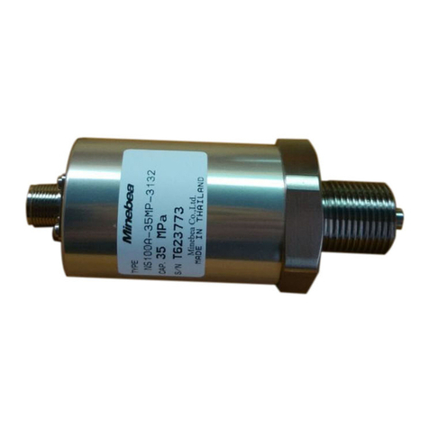
Minebea TMOFB-NM Series User manual

㻷㼀㻢㻜㻠㻠㻟㻙㻝㻳
䚷
TORQUE TRANSDUCER
TMOFB-*NM
(for Torque Transducer)
Instruction Manual
Sensing Device Business Unit
MinebeaMitsumi Inc.

KT60443-1G
Please read this manual thoroughly before attempting to use the equipment.
Be sure to observe the precautions provided in this section.
Keep this manual in a safe place where it can be referred to easily when required.
Pictograms and conventions used in this manual
This manual indicates the prohibited matters, notes and references with the following pictograms.
Be sure to read the descriptions provided alongside these pictograms with great care.
descriptions provided alongside these pictograms.
Caution against factors that may cause injury, accidents, or hazards
to personnel.
Avoid the actions described here at all times.
This indicates operating or procedural precautions or restrictions.
To avoid errors, be sure to read the details provided here.
Sec 1: Preface
Thank you for purchasing the MinebeaMitsumi Torque Transducer.
First, please make sure that the equipment has not been damaged during shipping, and that
the model is the one ordered.
If there are any problems, contact the Minebea sales office or dealer from which you
purchased the product.
Verify the individual model specifications by using the catalog or specifications.
Sec 2: Introduction
This equipment is capable of measuring both static and dynamic torque by using a thin-flange,
bearing-free torque transducer combining a torque detector flange calibrated by
attaching a strain gauge and an optical transformer that acquires a signal optically,
without making contact with the rotor.
Features include high precision, high stiffness, improved fatigue resistance,
and improved long-term consistency. The stator (antenna unit) has a split
configuration to facilitate mounting and detachment.
CAUTION
•Be sure to use the equipment within its rated operating capacity range.
•
•Mount the equipment by hex socket head bolts.
The bolt sizes used are indicated in this manual and in the specifications manual.
Select bolts with a JIS B 1051 strength classification of at least 10.9.
•In environments where the bolts are susceptible to coming loose, either make sure
the bolts are retightened periodically or include appropriate locking precautions.
•If the equipment is mounted on medical equipment or other devices with implications
for human life, make sure protective circuits are installed in case the equipment
stops functioning.
•Contact Minebea before attempting to use in special environments.
CAUTION
Do not apply voltages to the input terminals exceeding the maximum excitation voltage.
MinebeaMitsumi Inc. Sensing Device Business Unit
2

KT60443-1G
Sec 3:
Mounting Procedure
䚷䚷3-1. Typical mounting configuration (1) (2) (3) (4) (5)
(1) DY (dynamo)
(2) Torque transducer TMOFB-*NM
(3) Coupling (H-flange)
(4) Flexible coupling
(5) Intermediate bearing
䚷䚷3-2. Mounting flange
It may impede the power supply and cause zero balance shift or drifting
when metal objects' is close to the coil which attached to the
periphery of the flange on the equipment.
(1) Mounting unit outer diameter
Measured to the metal rim of the torque transducer flange.
• Ø155 mm max for TMOFB-500NM䡚3KNM
• Ø190 mm max for TMOFB-5KNM
(2) Distance from torque transducer flange edge face
At least 8 mm for A type mounting flange configuration (diameter extends to rotor)
At least 15 mm for B type mounting flange configuration (diameter extends to stator)
(3) Distance from torque transducer stator periphery (gap with protective cover etc.)
At least 10 mm from antenna outer diameter
䐟
䐠
䐡
Mounting flange
Coil winding area
Rotor
Stator (antenna)
(1)
(2)
(3)
MinebeaMitsumi Inc. Sensing Device Business Unit
3

KT60443-1G
䚷䚷3-3. Mounting procedure
(1) Mount the rotor on the rotating shaft.
Before mounting the rotor, wipe off the rust inhibitor on the flange and spigot using
ethanol or other solvent. Make sure mounting surfaces are free of debris.
Clamp using M12 (M14 for 5KNM) hex socket head bolts.
Regarding the rotor spigot as a guide and to fix with M12䠄M14 for 5KNM) hex socket head bolts.
(See Fig. 1.)
For specific tightening torques, see the separate tightening torque table.
Tighten the eight evenly-spaced bolts by tightening opposite pairs uniformly,
first, to 1/4 of the tightening torque; then to 1/2 of the tightening torque; then finally
to the specified tightening torque.
Please be careful when mounting in case of the damage to the transmission coil(Bakelite bobbin)
on the rotor periphery.
After mounting, peel off the green tape protecting the photo emitter.
Fig. 1
(2) Separate the stator (antenna) and mount aligned with the rotor.
Remove the 6-M6 hex socket head bolts marked as "A" in Fig. 2.
Separate the antenna as shown in Fig. 2.
Be careful to avoid losing the bolts or flat spring washers attached when detaching.
Insert the rotor inside before reassembling the separated antenna.
Install by sliding the stator on the alignment face in Fig. 1 to ensure the correct shaft
orientation.
Align the stator so that it does not make contact with the rotor anywhere along its periphery.
The stipulated gap between the stator and rotor is 4 mm. This can be aligned visually.
Attach the stator using M8 bolts with plain and spring washers.
After securing the stator, fully tighten the bolts on the separated antenna.
Malfunctions may occur if the bolts on the antenna are not properly tightened.
M14 for 5KNM M14 for 5KNM
Rotor/stator
alignment face
8-M12 socket head
bolts
Opposing flange
Section A
Stator (antenna)
Rotor
8-M12 socket head
bolts
Opposing flange
Photo emitter
(x8 evenly spaced)
Photoreceptor
Gap 3
Gap 4
MinebeaMitsumi Inc. Sensing Device Business Unit
4

KT60443-1G
Fig. 2
䚷䚷3-4. Mounting precautions
(1) Select fixing bolts with a JIS B 1051 strength classification of at least 10.9.
(2) Make sure the thread engagement length of the bolts is not less than the
nominal bolt diameter.
(3) Make sure the stator clamping base is sufficiently stiff and level.
(4) Be careful to avoid trapping debris and foreign matter inside when mounting.
(5) Never loosen any bolts other than those specified (6-M6) for separating the antenna.
(6) Tighten the bolts correctly. Use the tightening torque values given in the table below.
Tightening torque (N·m)
(N·m) (kgf·cm)
M6 13.7 140
M8 33.3 340
M12 115 1170
M14 176 1850
Nominal bolt
diameter
Stator
Rotor
Stator fixing bolts
4-M8
MinebeaMitsumi Inc. Sensing Device Business Unit
5

KT60443-1G
Sec 4: Measurement Preparation
(1) Wiring
Connect the dedicated cable with the transmitter to be used.
For more information, see the transmitter (CSA-562B) instruction manual.
(2) Calibration
Adjust the zero and calibrate the output when operating with no load.
For more information, see the transmitter (CSA-562B) instruction manual.
A positive torque output is generated when the rotor is twisted counterclockwise.
The output polarity is fixed and cannot be changed.
(3) Test running
Test run the equipment by operating at low speed. Confirm the absence of
abnormal output, noise, overheating, or vibration before starting measurement.
Sec 5: Maintenance and Inspection
This equipment transmits signals optically. This means the signal may not be transmitted
or received correctly if the photo emitter or photoreceptor is obscured by soot or other
contaminants. If necessary䠈keep the surfaces of the photo emitter and photoreceptor clean
by ethanol or other solvent.
Sec 6: Precautions
(1) This equipment transmits signals optically. While ambient fluorescent lights
should present no problems, infrared light from sunlight or incandescent lights
may cause malfunctions.
Use a protective cover to shield against outside light if the equipment is used in
locations where sunlight or incandescent lights are present.
(2) The antenna stator conveys a current to transmit the input voltage.
Do not allow it to come into contact with covers in the vicinity or other metal objects.
(3) Two signal output connectors are located on the left and right of the stator.
These are provided to allow the cable to be connected to either side to suit
the installation configuration. Make sure that only one connector is used at any given time.
The signal cannot be output from both connectors simultaneously.
(4) This is a rotating part. Keep a protective cover fitted at all times to prevent
material from flying out.
(5) Vibration may result if the equipment balance is upset after attaching the coupling.
Adjust the dynamic balance for the equipment as a whole after combining the
torque transducer with the coupling and other devices.
(6) Impact loads or vibrations will subject the torque transducer to dynamic loads
consisting of the static load multiplied by the acceleration.
Make sure the value taking into account the acceleration does not exceed the
rated capacity of the torque transducer.
(7) Install safety devices to prevent damage if there is a likelihood of excessive
loads acting on the torque transducer.
(8) Make sure the installation location is sufficiently strong.
(9) Use the equipment at ambient temperatures within the compensation temperature range.
(10) Avoid locations subject to sudden temperature fluctuations or direct heat sources.
(11) Check the protection rating. Make sure the equipment is used under conditions
free of condensation.
(12) Avoid using the equipment in the presence of strong electromagnetic fields.
Or it may cause noise interference.
(13) Take care when handling the transmission coil, photo emitter,
and photoreceptor. These parts are especially delicate.
MinebeaMitsumi Inc. Sensing Device Business Unit
6

KT60443-1G
(14) Avoid bending or pulling the cable outlet with excessive force.
Do not grasp the stator by the cable when carrying it.
(15) If being used in vibration conditions, secure the cable close to the cable
outlet to keep it from vibrating.
(16) In environments where the bolts are susceptible to coming loose,
either make sure the bolts are retightened periodically or
include appropriate locking precautions.
(17) If the equipment is mounted on medical equipment or other devices with
implications for human life, make sure protective circuits are installed in
case the torque transducer stops functioning.
(18) Do not disassemble the torque transducer.
(19) Avoid dropping objects to impact on the torque transducer.
(20) Follow applicable environmental guidelines when disposing of the equipment.
Sec 7: Troubleshooting
If the equipment is subjected to loads or speeds exceeding permissible tolerances
or if the equipment is subjected to excessive loads in the bending and thrust directions,
be sure to recalibrate and verify that the equipment can be used correctly.
If the reading is unstable or abnormal, check that the instruments are correctly
connected and confirm compliance with all usage precautions before inspecting
the torque transducer as follows.
(1) Use the CHECK switch on the transmitter to confirm that the check value is normal.
(2) Confirm that the output changes when the rotor is twisted by hand.
(3)
Confirm that the output (zero balance) with no load is not significantly out of adjustment.
Contact Minebea if the above measurements are abnormal.
Contact Minebea if you have any queries about connection procedures or other matters.
Please note that the information provided in this manual is subject to change without notice.
MinebeaMitsumi Inc. Sensing Device Business Unit
7


䖃The contents of this manual may subject to change without notice.
HEAD QUARTER: MinebeaMitsumi Inc.
4106-73 Miyota, Miyota-machi, Kitasaku gun, Nagano-ken 389-0293 Japan
Tel: +81-267-32-2200 Fax: +81-267-31-1350
Sensing Device Product Sales Management:
1-1-1, Katase, Fujisawa-shi, Kanagawa-ken, 251-8531 Japan
Tel: +81-466-23-2681 Fax: +81-466-22-7191
Sensing Device Business Unit
FUJISAWA PLANT 1-1-1, Katase, Fujisawa-shi, Kanagawa-ken, 251-8531 Japan
Tel: +81-466-22-7151 Fax: +81-466-22-1701
KARUIZAWA PLANT 4106-73 Miyota, Miyota-machi, Kitasaku gun, Nagano-ken 389-0293 Japan
Tel: +81-267-31-1309 Fax: +81-267-31-1353
HOMEPAGE ADDRESS http://www.minebea-mcd.com
This manual suits for next models
3
Other Minebea Transducer manuals
Popular Transducer manuals by other brands

S+S Regeltechnik
S+S Regeltechnik THERMASGARD MWTM Series Operating Instructions, Mounting & Installation

Balluff
Balluff Micropulse BTL5-A series user guide

S&S Northern
S&S Northern Merlin 2000S Installation & operation manual

aci
aci ACCESS series Installation & operation instructions

Navman
Navman TRANSOM MOUNT installation manual

Mianyang Weibo Electronic
Mianyang Weibo Electronic WBI415S91 user manual