MiNGARDi G1 User manual

]
5071475 - 04/11
Centralina G1
[
INDICE
AVVERTENZE GENERALI
- AVVERTENZE GENERALI
- DESCRIZIONE
- CARATTERISTICHE
- DOTAZIONE
- INSTALLAZIONE
Prima di intraprendere qualsiasi operazione di installazione o collegamento elettrico, leggere con estrema atten-
zione queste avvertenze.
L’utilizzatore è tenuto a prendere visione delle note in esse riportate e a conservarle per eventuali ulteriori con-
sultazioni.
Consultare l’istruzione generale Linea G1, scaricabile dal sito internet: www.way-srl.com per quanto:
- non espressamente indicato in questo opuscolo
- attiene alle caratteristiche applicative dei dispositivi destinati in sistemi di ventilazione ed
Evacuazione Naturale di Fumo e Calore
La Window Automation industrY si riserva il diritto di apportare qualsiasi modifica/miglioria al contenuto della pre-
sente pubblicazione senza l’obbligo di comunicarlo, qualora non vi siano ricadute dal punto di vista prestazionale
e normativo.
- FUNZIONAMENTO E
CONNESSIONE ACCESSORI
- COLLAUDO
- MANUTENZIONE
- ACCESSORI – RICAMBI
DEFINIZIONE SIMBOLOGIA
Attenzione!
Leggere attentamente queste avvertenze.
Attenzione!
Evidenzia note da tenere in considerazione per evitare danni all’attuatore.
Informazione.
Si riferisce a informazioni importanti alle quali prestare attenzione.
ATTENZIONE
Window Automation industrY Srl a socio unico
Via C. Bassi, 7/A - 40015 Galliera (BO) - Italy - Tel. +39.051.6672711 - Fax +39.051.6672790

Pericolo!
Indicazione di un pericolo che potrebbe causare lesioni alle persone.
Pericolo!
Pericolo di schiacciamento delle mani.
PERICOLO
NOTE RELATIVE ALLA CENTRALE ANTINCENDIO
• La Centrale antincendio è conforme alle direttive vigenti di appartenenza.
• La garanzia per un funzionamento sicuro è legata al rispetto da parte degli installatori delle norme di
sicurezza in vigore nel paese d’installazione.
• L’uso della Centrale antincendio per altre applicazioni deve essere autorizzato previo una verifica
tecnica dell’applicazione.
• Installare la Centrale antincendio utilizzando esclusivamente accessori originali o approvati.
IMPORTANTI ISTRUZIONI PER LA SICUREZZA
È importante per la sicurezza delle persone, seguire fedelmente tutte le istruzioni di seguito riportate
Un’installazione non corretta può rendere l’applicazione pericolosa.
• La Centrale antincendio non è un organo strutturale del serramento (cupola, lucernaio,ecc.)
• I pulsanti /dispositivi di comando devono essere posti al di fuori del raggio di azione della parte mo-
bile del serramento (cupola, lucernaio,ecc.).
• Non permettere ai bambini di giocare con i comandi fissi o remoti.
• Quando si comanda l’apertura o la chiusura del serramento (cupola, lucernaio,ecc.) assicurarsi che
altre persone siano a distanza dalle parti in movimento, anche se ottenuta da un sistema di rileva mento.
• Si raccomanda di scollegare l’alimentazione della Centrale antincendio durante le operazioni di ma-
nutenzione, in particolare se dotata di un dispositivo di comando automatico.
• Controllare che nessun oggetto ostacoli il movimento del serramento (cupola, lucernaio,ecc.). Non
effettuare mai in caso di guasti interventi sulla Centrale antincendio, non aprire o smontare parti
della Centrale antincendio. In caso di guasti o danni alla Centrale antincendio rivolgersi a personale
specializzato; non utilizzare fino a che non sia stato riparato il guasto.
• Durante le operazioni di montaggio e/o smontaggio della Centrale antincendio dall’impianto, adottare
opportuni accorgimenti per prevenire sbattimenti accidentali, possibili rotture del serramento (cupola,
lucernaio,ecc.) e lesioni all’operatore.
• Per consentire un eventuale arresto di emergenza, si consiglia l’utilizzo di comando collocato in
posizione dove il serramento (cupola, lucernaio,ecc.) sia visibile.
Durante I’uso osservare le seguenti norme di comportamento:
Centrale antincendio monozona a 2 linee a cui è possibile collegare fino a 10 rilevatori di fumo (rif.10) o di calore
(rif. 12), in parallelo.
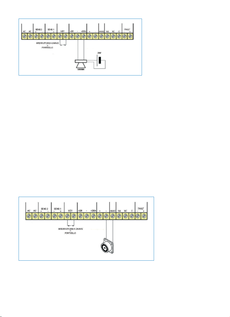
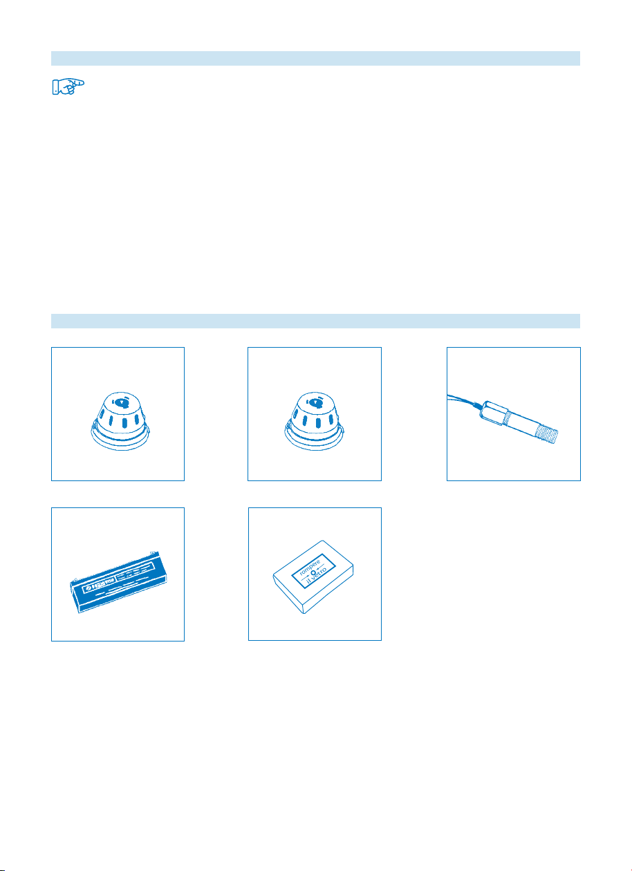
Alla centrale antincendio possono essere asserviti elettromagneti di ritenuta per porte tagliafuoco, sirene o avvi-
satori acustici (accessori non commercializzati da Window Automation industrY Srl).
In caso di incendio comanda automaticamente l’apertura degl’impianti pneumatici per evacuazione naturale di
fumo e calore.
All’interno del contenitore metallico della centrale antincendio devono essere alloggiate n°2 batterie da 12V di
capacità max 2,1Ah (rif. 15), non in dotazione; vengono mantenute in carica da apposito circuito per garantire, il
funzionamento della centrale antincendio in mancanza di corrente elettrica.
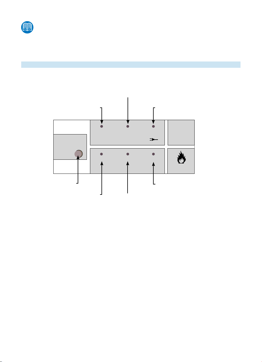
E’ provvista di spie che segnalano
- l’interruzione nelle linee di rilevazione
- l’interruzione della linea di alimentazione della Centrale antincendio
- l’allarme in corso
DESCRIZIONE

TENSIONE DI ALIMENTAZIONE 230V~ +6% -10% 50Hz
CORRENTE MAX ASSORBITA 250mA~
TENSIONE NOMINALE 24Vdc
TEMPERATURA DI ESERCIZIO Max 40°C Min 5°C
BATTERIA 2,1Ah 12Vdc (n° 2)
CORRENTE MAX EROGATA 1,1A (100mA consumo centrale antincendio)
CORRENTE RICARICA BATTERIE 380mA
CORRENTE ALIMENTAZIONE MAGNETI 620mA
CORRENTE MINIMA PER PROVOCARE UN
ALLARME 6,5mA
CARATTERISTICHE
DOTAZIONE ALLA CENTRALE ANTINCENDIO
INSTALLAZIONE
Solo per personale tecnico preposto all’installazione.
Le operazioni di montaggio e di collegamento elettrico, pneumatico, ecc. della Centrale antincendio de-
vono essere eseguite da personale specializzato dotato di adeguata preparazione professionale e cono-
scenze specifiche delle normative tecniche di riferimento e antinfortunistiche.
OPERAZIONI DA ESEGUIRE PRIMA DI MONTARE I BOX COMANDO DI EMERGENZA
Verificare che:
• I profili e i fissaggi siano adeguatamente dimensionati per sopportare le sollecitazioni prodotte dall’azionamento.
• I tipi di cerniere o ferramenta utilizzati, consentano la completa corsa del cilindro/attuatore/altro, al fine
di evitare danni alle strutture provocati dalla forza di trazione o di spinta.
• Gli impianti siano conformi alle norme vigenti nel paese d’installazione.
• L’imballo contenga tutti i componenti e accessori previsti per l’installazione.
• Il dispositivo contenuto all’interno della confezione, sia integro.
- Proteggere i componenti dall’ingresso di polvere ed acqua prima dell’installazione.
- Nel caso di utilizzo anche per ventilazione, utilizzare aria filtrata e deumidificata.
• Se l’apertura del serramento (cupola, lucernaio,ecc.) è limitata da accessori di sicurezza potrebbero
prodursi danni al serramento (cupola, lucernaio,ecc.).
• Pericolo di schiacciamento delle mani.
• Durante il movimento del battente non interporre le mani fra il telaio fisso e le parti mobili.
SCHEMA
COLLEGAMENTO
PONTICELLO
FERMACAVO +
FASCETTA
RESISTENZA 2,2kΩ (6pz)
RELE’ +
PORTARELE’ FINDER

• Prima di collegare alla centrale gli attuatori pirotecnici, mettere in funzione la Centrale antincendio e
premere “RESET”.
• Posizionare la Centrale antincendio come da progetto dell’impianto di Evacuazione Naturale di Fumo
e Calore. Fissarlo stabilmente a parete.
L’altezza da terra deve essere tale da rendere possibile l’accesso all’azionamento da
parte del personale preposto.
FUNZIONAMENTO E CONNESSIONE ACCESSORI
PANNELLO DI CONTROLLO DELLA CENTRALE ANTINCENDIO
Tramite i led del pannello di controllo della centrale antincendio è possibile, in tutte le condizioni, verificare lo stato
della centrale antincendio.
In stato di riposo deve essere acceso solo il led di “PRESENZA TENSIONE DI RETE 230Vac”
CONDIZIONE ALLARME INCENDIO
Nel caso di allarme incendio su una linea:
1. il led ALLARME ZONA corrispondente alla linea in allarme (SENS 1 – SENS 2) viene acceso per la durata
dell’allarme.
2. viene attivata l’uscita sirena (se abilitata tramite chiave KEY) per la durata dell’allarme.
3. viene attivata l’uscita magneti (se abilitata tramite chiave KEY e/o ponticello W2 inserito).
4. il relè di scambio si chiude su C-NA (se abilitato tramite chiave KEY e/o ponticello W2 inserito).
CONDIZIONE DI FINE ALLARME INCENDIO
Al termine dell’allarme incendio:
1. il led ALLARME ZONA corrispondente alla linea in allarme si spegne.
2. le uscite sirena e magneti si disattivano ed il relè di scambio si chiude tra C-NC.
CONDIZIONE DI GUASTO
Nel caso di cortocircuito o di interruzione di corrente su di una linea d’allarme incendio, la centrale antincendio
entra in condizione di guasto.
1. il led GUASTO LINEA corrispondente alla linea in allarme (SENS 1 – SENS 2) viene acceso per la durata
dell’allarme.
SEGNALAZIONE DI ALLARME / GUASTO
1
1OFF
T20IN
2
2
FAULT-GUASTO-DEFAUT
FIRE-INCENDIO-INCENDIE
RESET
GUASTO LINEA 1
LED SPENTO = Nessun guasto
LED ACCESO = Presenza guasto
PRESENZA TENSIONE DI RETE 230Vac
LED SPENTO = assenza rete
LED ACCESO = presenza rete
GUASTO LINEA 2
LED SPENTO = Nessun guasto
LED ACCESO = Presenza guasto
PULSANTE RESET
SENSORI INCENDIO
ALLARME ZONA 1
LED SPENTO = Nessun allarme
LED ACCESO = Allarme in corso ALLARME ZONA
LED SPENTO = Nessun allarme
LED ACCESO = Allarme in corso
ABILITAZIONE USCITE
LED SPENTO = Uscite abilitate
LED ACCESO = Uscite disabilitate

ALIMENTAZIONE
Si raccomanda di scollegare l’alimentazione della Centrale antincendio durante le operazioni di collega-
mento alla rete elettrica.
Collegare il polo “+” di una batteria (rif.15 ) ed il polo “-“ dell’altra batteria (rif.15 ) mediante i cavetti ROSSO
(polo “+”) e NERO (polo “-“). Utilizzando il ponticello in dotazione collegare tra di loro i rimanenti 2 poli “+” e “-”
delle batterie (rif.15 ).
La centrale antincendio è alimentata attraverso la tensione di rete 230Vac, tramite un cavo di alimentazione a
doppio isolamento (con guaina supplementare) che deve essere connesso agli appositi morsetti del trasformatore
di ingresso (L, N, ).
Il cavo di alimentazione deve essere vincolato alla centrale antincendio tramite fascetta e ferma cavi (in dotazione).
IL CAVO DI ALIMENTAZIONE NON VIENE FORNITO INSIEME ALLA CENTRALE ANTINCENDIO.
LINEE DI INGRESSO
Sulla morsettiera della scheda elettronica della centrale antincendio sono presenti le seguenti linee di ingresso:
Linee di ingresso: SENS1 e SENS2 (schema 1)
La centrale antincendio è dotata di 2 linee di ingresso SEMPRE attive.
Su ogni linea possono essere collegati fino a 10 rilevatori di fumo (rif. 10) o di calore (rif.12) o pulsante d’emer-
genza (rif.16).
Ad ogni fine linea, anche se non vengono utilizzate, è necessario bilanciare il circuito con una resistenza RL da
2,2kΩ (in dotazione).
Nel caso si desideri collegare un pulsante d’emergenza (rif.16), oltre ad una resistenza di fine linea RL da 2,2kΩ
(in dotazione), si devono collegare n°2 resistenze (RA) da 2,2kΩ in parallelo (in dotazione) o in alternativa n° 1
resistenza da 1,8 kΩ (non in dotazione).
2. viene attivata l’uscita guasti (FAULT attivo = presenza di positivo)
3. le uscite sirene, magneti e relè di scambio non vengono attivati.
CONDIZIONE DI FINE GUASTO
Al termine del guasto:
1. il led GUASTO LINEA corrispondente alla linea in allarme (SENS 1 – SENS 2) si spegne.
2. viene disattivata l’uscita guasti (FAULT disattivo = assenza di positivo
CONDIZIONE DI BATTERIA BASSA
Quando la tensione della batteria è inferiore a 23V, viene attivata l’uscita guasti (FAULT attivo = presenza di
positivo).
Al termine del guasto, viene disattivata l’uscita guasti (FAULT disattivo = assenza di positivo).
Schema 1

Chiave: KEY (Schema 2)
L’ingresso della chiave abilita/disabilita le uscite sirena (ed attuatori pirotecnici), relè di scambio e relè magneti.
Ingresso chiuso: Abilitate le sirene (ed attuatori pirotecnici), i relè di scambio ed i relè magneti. Deve essere inserito il
ponticello W2.
Il led “OFF” sul pannello di controllo della centrale antincendio è spento.
Ingresso aperto: Disabilitate le sirene (ed attuatori pirotecnici), i relè di scambio ed i relè magneti.
Il led “OFF” sul pannello di controllo della centrale antincendio è acceso.
USCITE
Sulla morsettiera della scheda elettronica della centrale antincendio sono presenti le seguenti uscite:
USCITA RELE’ SIRENE: +SR +SRA (Schema 3 – Schema 4)
Le uscite sirena, se abilitate con chiave KEY, sono attive per tutta la durata dell’allarme.
Uscita Relè Sirena (+SR, -)
Nessun allarme = Assenza 24V
Allarme incendio = Presenza 24V
Uscita Relè Sirena (+SRA, -)
Nessun allarme = Presenza 24V
Allarme incendio = Assenza 24V
Le uscite sono protette da un fusibile da 2,5A.
Sull’uscita relè è possibile collegare in serie alla sirena, degli attuatori pirotecnici (rif. 13).
Il collegamento deve avvenire tramite il relè Finder
a 2 scambi mod. 46.52, con assorbimento nomi-
nale 20mA e corrente nominale 8A (in dotazione).
Ad ogni scambio del relè è possibile collegare un
circuito composto da una batteria che alimenta 1 o
più attuatori pirotecnici in parallelo.
Si raccomanda di leggere attentamente l’istruzione
dell’attuatore pirotecnico commercializzato dalla
Window Automation industrY srl.
Il numero massimo di attuatori dipende dalla cor-
rente di scarica della batteria utilizzata e dalla
corrente minima di accensione dell’attuatore piro-
tecnico stesso. La Window Automation industrY srl
consiglia di non collegare più di 5 attuatori pirotec-
nici per ogni scambio del relè Finder, utilizzando
una batteria di capacità adeguata.
È possibile collegare in serie, oltre ad una sirena
Schema 2
Schema 3

modulare (max 500mA) fino ad un mas-
simo di 10 relè Finder a 2 scambi mod.
46.52 (in dotazione solo 1), in quanto:
Le uscite sono protette da un fusibile da
2,5A.
L’assorbimento nominale di ogni relè è
di 20mA.
Ne risulta che:
(20mA x 10) + 500mA = 2500mA (2,5A).
La Window Automation industrY srl con-
siglia di non collegare più di 5 relè Finder
a 2 scambi mod. 46.52
USCITA RELE’ DI SCAMBIO: NA, NC, C
Il relè di scambio è attivo per tutta la durata dell’allarme a meno che non venga disabilitato attraverso chiave (KEY) e/o
attraverso il ponticello W2.
Ponticello W2 inserito = relè pilotato in caso di incendio.
Ponticello W2 non inserito = relè non pilotato
Nessun allarme = Contatto C – NC
Allarme incendio = Contatto C – NA
Il relè di scambio è protetto da un fusibile da 1A.
USCITA MAGNETI: +MAG (Schema 5)
L’uscita magneti, se abilitata attraverso chiave (KEY) e/o attraverso il ponticello W2, viene commutata ogni volta che
viene rilevato un allarme incendio.
È normalmente utilizzata per comandare porte tagliafuoco (elettromagnetiche) Max 24V, 620mA.
Ponticello W2 inserito = uscita (+MAG) pilotata in caso di incendio.
Ponticello W2 non inserito = uscita (+MAG) non pilotata
Nessun allarme = Presenza 24V (su +MAG)
Allarme incendio = Assenza 24V (su +MAG)
Il relè di scambio è protetto da un fusibile da 1A.
È possibile collegare più elettromagneti in serie. Il numero massimo dipende dalla corrente assorbita dall’elettromagnete
utilizzato (max 1A).
USCITA ALIMENTAZIONE AUSILIARIA: + , -
È disponibile un’ulteriore uscita ausiliaria 24V (+) protetta da fusibile da 1A per utilizzi vari,
Attenzione: in caso di mancanza di corrente elettrica, l’accessorio collegato a questa entrata utilizzerà le batterie, contri-
buendo a ridurne la durata.
Schema 4
Schema 5

USCITA GUASTI: FAULT - , +
In caso di guasto ad una linea dovuta ad un cortocircuito od ad un’interruzione, o in caso di batteria con tensione inferiore
a 23V, viene attivata l’uscita guasti.
FAULT attivo = presenza di positivo (+).
Il collaudo deve esser eseguito sulla base della documentazione di progetto dell’Impianto
- inizia con la verifica di conformità dell’Impianto e dei propri componenti
- successivamente con la conduzione delle prove funzionali nel rispetto delle Normative di riferimento.
Il collaudo più completo è quello nel quale si simula un incendio, producendo fumo e calore sotto un
rivelatore di ogni compartimento.
Consultare l’istruzione generale Linea G1, scaricabile dal sito internet: www.way-srl.com per docu-
mentarsi sulle caratteristiche delle operazioni da condurre a carico di tutti i componenti di cui l’Impianto
stesso, da eseguire in accordo tra le parti: Autorità locali, Vigili del Fuoco, Committente, ecc. in quanto:
- vi sono componenti che possono essere utilizzati una sola volta, dopodiché devono essere sostituiti
- alcuni Evacuatori possono riportare danni e/o deformazioni che, se non inficiano mobilità e rendimen-
to dell’Evacuatore in quanto tale, tuttavia possono deteriorarne le caratteristiche di tenuta all’aria ed
all’acqua.
COLLAUDO
FUSIBILE 1A (F3)
PONTICELLO W2
FUSIBILE 1A (F2)
FUSIBILE 2,5A (F1)

E’ necessario programmare controlli periodici per avere la garanzia che la centralina G1 conservi la
massima efficienza e sia pronta ad intervenire in ogni momento.
Consultare l’istruzione generale Linea G1, scaricabile dal sito internet:
www.way-srl.com per procedere con le operazioni da effettuarsi:
a) come prescritto dalle Normative vigenti (tra le quali D.M.del 10 Marzo 1998, allegato VI)
b) con periodicità rispettivamente di
- 6 mesi
- 1 anno
- 2 anni
- 4 anni
- comunque dipendenti anche da condizioni ambientali in cui deve operare l’Impianto (es.: ambienti
umidi, aggressivi, ecc.) e da integrarsi con tutte le altre parti che compongono l’Impianto stesso
(es.: integrità delle linee di collegamento, efficienza del sistema di rivelazione, stato delle batterie
tampone, ecc.)
10. Rilevatore di fumo 12. Rilevatore di calore 13. Attuatore pirotecnico
15. Batteria 12V – 2 A 16. Pulsante d’emergenza
Vedere istruzione specifica! Vedere istruzione specifica!
Vedere istruzione specifica!
rompere
il vetro
ACCESSORI - RICAMBI
MANUTENZIONE

Note [

]
G1 Control unit
[
INDEX
GENERAL WARNINGS
- GENERAL WARNINGS
- DESCRIPTION
- FEATURES
- EQUIPMENT
- INSTALLATION
Before undertaking any installation or electrical connection, read these instructions carefully.
The user is required to read the notes contained in these instructions and keep them for further consultation.
Refer to Line G1 general instructions, downloadable from website www.way-srl.com with regard to:
- anything not mentioned in this brochure
- the application characteristics of devices used for Ventilation Systems and Natural Smoke and Heat Extractors
Systems.
Window Automation industrY reserves the right to make any changes/improvements to the content of this publi-
cation without obligation to notify, provided there are no consequences in terms of performance and regulations.
- ACCESSORIES OPERATION
AND CONNECTION
- TESTS
- MAINTENANCE
- ACCESSORIES – SPARE PARTS
DEFINITION OF SYMBOLS
Attention!
Carefully read these instructions.
Attention!
Highlights notes to be taken into account to avoid damage to the actuator.
Information.
This refers to important information to pay attention to.
ATTENTION
Window Automation industrY Srl a socio unico
Via C. Bassi, 7/A - 40015 Galliera (BO) - Italy - Tel. +39.051.6672711 - Fax +39.051.6672790
5071475 - 04/11

Danger warning!
Indicates a hazard that could result in injury.
Danger warning!
Danger of crushing hands.
DANGER WARNING
NOTES ON THE FIRE ALARM CONTROL UNIT
• The Fire alarm control unit complies with the pertinent directives in force.
• The guarantee for safe operation is linked to the compliance, on behalf of installers, of the safety rules
in force in the country of installation.
• The use of the Fire alarm control unit for other applications must be authorized, after technical
verification of the application.
• Install the Fire alarm control unit using only original or approved accessories.
IMPORTANT SAFETY INSTRUCTIONS
It is important to carefully follow all the instructions listed below to ensure everyone’s safety.
Improper installation could make the application dangerous.
• The Fire alarm control unit is not a structural component of the window (dome, skylight, etc.).
• The buttons/control devices must be on the outside of the ray of action of the window’s mobile part
(dome, skylight, etc.).
• Do not allow children to play with the fixed or remote controls.
• When controlling the opening or closing of the window (dome, skylight, etc.), make sure that other peo-
ple are at a certain distance from the moving parts, even if it this is done by a detection system.
• It is recommended to disconnect the power supply of the Fire alarm control unit during maintenance,
especially if it is equipped with an automatic control device.
• Check that no object impedes the movement of the window (dome, skylight, etc.). Never work on the
Fire alarm control unit in case of failure and do not open or disassemble parts of the Fire alarm control
unit. In the event of failure or damage to the Fire alarm control unit contact a specialist and do not use
it until the fault has been repaired.
• During the assembly/disassembly of the Fire alarm control unit to/from the system, take appropriate
precautions to prevent accidental slamming, breakage of the window (dome, skylight, etc.) and operator
injuries.
• In order to perform emergency stops, it is advisable to use the control located in a position where the
window (dome, skylight, etc.) is visible.
During use, observe the following rules of conduct:
Monozone, 2-line fire alarm control unit that can connect up to 10 smoke detectors (ref.10) or heat detectors
(ref. 12), in parallel.
The Fire alarm control unit can be interlocked with latching electromagnets for fire doors, sirens or acoustic
signals (accessories not marketed by Window Automation industrY Srl).
In case of fire, it automatically controls the opening of the pneumatic systems for the natural extraction of smoke
and heat.
The Fire alarm control unit’s metal box must house 2 12-Volt batteries, 2.1Ah max. capacity (ref. 15), not inclu-
ded; they are kept charged by a special circuit to ensure operation of fire alarm control unit in the absence of
electric current.
The control unit is equipped with warning lights that signal the following events:
- detection line cut-outs
- fire alarm control unit power line cut-out
- the current alarm
DESCRIPTION

POWER SUPPLY VOLTAGE 230V~ +6% -10% 50Hz
MAX ABSORBED CURRENT 250mA~
RATED VOLTAGE 24Vdc
OPERATING TEMPERATURE Max 40°C Min 5°C
BATTERY 2,1Ah 12Vdc (n° 2)
MAX OUTPUT CURRENT 1,1A (100mA Fire alarm control unit consumption)
BATTERY CHARGE CURRENT 380mA
MAGNETS POWER SUPPLY CURRENT 620mA
MINIMUM CURRENT TO TRIGGER
AN ALARM 6,5mA
FEATURES
FIRE ALARM CONTROL UNIT EQUIPMENT
INSTALLATION
Only for technical personnel responsible for installation.
The assembly operations, the wiring and pneumatic connections, etc. of the Fire alarm control unit must
be performed by professionally prepared, qualified personnel who have adequate knowledge of the rele-
vant accident prevention technical standards.
OPERATIONS TO BE PERFORMED BEFORE MOUNTING THE EMERGENCY CONTROL BOXES
Check that:
• The profiles and fixings are capable of withstanding the stress produced by the drive.
• The types of hinges or hardware used enable the entire stroke of the cylinder/actuator/other, in order to
avoid damage to structures caused by the pushing or puling force.
• The systems comply with current standards in the country of installation.
• The packing contains all the components and accessories required for the installation.
• The device contained inside the package is undamaged.
- The components are protected from dust and water before installation.
- When used also for ventilation, use filtered and dehumidified air.
• If the opening of the window (dome, skylight, etc.) is limited by safety accessories, the window (dome,
skylight, etc.) could undergo damage.
• Danger of crushing hands.
• While the window is moving, do not put your hands between the fixed frame and the mobile parts.
WIRING DIAGRAM
JUMPER
CABLE RETAINER +
CLAMP
RESISTANCE 2,2kΩ (6pz)
FINDER RELAY +
RELAY-HOLDER

• Before connecting the pyrotechnic actuators to the control unit, start the Fire alarm control unit and
press “RESET”.
• Place the Fire alarm control unit according to the design of the Smoke and Heat Natural Extraction
system. Secure it firmly to the wall.
Its height from the ground should be such that staff in charge of actuating it are able to reach and access it.
ACCESSORIES OPERATION AND CONNECTION
FIRE ALARM CONTROL UNIT CONTROL PANEL
You can check the status of the Fire alarm control unit, in all conditions, through the LEDs on its control panel.
In the resting state, only the “230Vac MAINS VOLTAGE PRESENCE” LED should be ON.
FIRE ALARM CONDITION
In the event of a fire alarm in a line:
1. the ZONE ALARM LED corresponding to the alarmed line (SENS 1 – SENS 2) turns on and stays on for the
duration of the alarm.
2. the siren output is activated (if enabled through the KEY switch) for the duration of the alarm.
3. the magnets output is activated (if enabled through the KEY switch and/or jumper W2 inserted).
4. the exchange relay closes on C-NO (if enabled through the KEY switch and/or jumper W2 inserted).
FIRE ALARM END CONDITION
At the end of the fire alarm:
1. the ZONE ALARM LED corresponding to the alarmed line turns off.
2. the siren and magnets outputs deactivate and the exchange relay closes between C-NC.
FAULT CONDITION
In the case of short circuit or power failure on a fire alarm line, the Fire alarm control unit enters a fault condition.
1. the LINE FAULT LED corresponding to the alarmed line (SENS 1 – SENS 2) turns on and stays on for the
duration of the alarm.
2. the faults output is activated (FAULT active = presence of the positive)
3. the sirens and magnets outputs and the exchange relay do not activate.
ALARM/FAULT WARNING
1
1OFF
T20IN
2
2
FAULT-GUASTO-DEFAUT
FIRE-INCENDIO-INCENDIE
RESET
LINE 1 FAULT
LED OFF: no fault
LED ON: fault present
MAINS VOLTAGE PRESENCE 230Vac
LED OFF: mains absent
LED ON: mains present
LINE 2 FAULT
LED OFF: no fault
LED ON: fault present
RESET BUTTON
FIRE DETECTION SENSORS
ALARM IN ZONE 1
LED OFF: no alarm
LED ON: alarm in progress ZONE ALARM 2
LED OFF: no alarm
LED ON: alarm in progress
OUTPUTS ENABLING
LED OFF = Outputs enabled
LED ON = Outputs disabled

POWER SUPPLY
It is recommended to disconnect the power supply of the Fire alarm control unit when connecting it to
the mains.
Connect the “+” pole of one battery (ref.15) and the “-” pole of the other battery (ref.15) through the RED (“+”
pole) and BLACK (“-” pole) wires. Using the jumper supplied, connect the other 2 “+” and “-” poles of the bat-
teries (ref.15) to one another.
The Fire alarm control unit is powered by the 230Vac mains voltage via a power cord with double insulation (with
additional sheath) which must be connected to the appropriate terminals of the input transformer (L, N,).
The power cord must be bound to the Fire alarm control unit via cable retainers and clamps (supplied).
THE POWER CORD IS NOT PROVIDED WITH THE FIRE ALARM CONTROL UNIT.
INPUT LINES
The following input lines are present in the Fire alarm control unit’s electronic card terminal strip:
Input lines: SENS1 and SENS2 (diagram 1)
The Fire alarm control unit has 2 input lines that are ALWAYS active.
Up to 10 smoke detectors (ref. 10) or heat detectors (ref.12) or up to emergency buttons (ref.16) can be connected
on each line.
At the end of each line, even when the lines are not in use, you must balance the circuit with a 2.2kΩ RL resistance
(supplied).
In case you want to connect an emergency button (ref.16), in addition to a 2.2kΩ RL line end resistance (supplied),
you must connect two 2.2kΩ (RA) resistances in parallel (supplied) or one 1.8 kΩ resistance (non supplied).
FAULT END CONDITION
At the end of the fault:
1. the LINE FAULT LED corresponding to the alarmed line (SENS 1 – SENS 2) turns off.
2. the faults output is deactivated (FAULT inactive = absence of the positive)
LOW BATTERY CONDITION
When battery voltage is below 23V, the fault output is activated (FAULT active = presence of the positive).
At the end of the fault, the fault output is deactivated (FAULT inactive = absence of the positive).
EMERGENCY BUTTON
RL = LINE END RESISTANCE 2.2 Kohm (supplied)
RA = ALARM RESISTANCE
n°2 resistances 2.2 Kohm in parallel (supplied)
o
n°1 resistance 2.2 Kohm in parallel (non supplied)
RF = SMOKE OR HEAT DETECTOR (max 10)
Schema 1

KEY SWITCH (Diagram 2)
The input of the key switch enables/disables the siren (and pyrotechnic actuators), exchange relays and magnets relays
outputs.
Input closed: the sirens (and pyrotechnic actuators), exchange relays and magnets relays are enabled. Jumper W2 must
be inserted.
The “OFF” LED on the control panel of the Fire alarm control unit is OFF.
Input open: the sirens (and pyrotechnic actuators), exchange relays and magnets relays are disabled
The “OFF” LED on the control panel of the Fire alarm control unit is ON.
OUTPUTS
The following outputs are present in the Fire alarm control unit’s electronic card terminal strip:
SIREN RELAYS OUTPUT: +SR +SRA (Diagram 3 – Diagram 4)
The siren outputs, if enabled with the KEY switch, are active for the duration of the alarm.
Siren Relay Output (+SR, -)
No alarm = 24V absence
Fire alarm = 24V presence
Siren Relay Output (+SRA, -)
No alarm = 24V presence
Fire alarm = 24V absence
The outputs are protected by a 2.5A fuse.
Pyrotechnic actuators (ref. 13) can be connected on the relay output in series with the siren.
Make the connection through the 2-exchange Fin-
der relay mod. 46.52, with 20mA nominal absorption
and 8A rated current (supplied).
You can connect a circuit, to each relay exchange,
consisting of a battery that powers 1 or more pyro-
technic actuators in parallel.
Please carefully read the instructions of the pyro-
technic actuator marketed by Window Automation
industrY srl.
The maximum number of actuators depends on the
discharge current of the battery used and the pyro-
technic actuator’s minimum ignition current.
Window Automation industrY srl recommends not
connecting more than 5 pyrotechnic actuators for
each Finder relay exchange, using a battery of sui-
table capacity.
You can connect, in series and in addition to a mo
KEY SWITCH
CONTROL UNIT OFF
“OFF” LED ON
CONTROL UNIT ON
“OFF” LED OFF
MODULAR SIREN
MAX 500 mA
PYROTECHNIC ACTUATOR
Battery
Battery
KEY SWITCH
OR
JUMPER
Schema 3
Schema 2

dular siren (max 500mA), up to a ma-
ximum of 10 Finder 2-exchange relays
mod. 46.52 (only 1 supplied), because:
The outputs are protected by a 2.5A fuse.
Nominal absorption of each relay is
20mA.
As a result:
(20mA x 10) + 500mA = 2500mA (2.5A).
Window Automation industrY srl recom-
mends not connecting more than 5 Fin-
der 2-exchange relays mod. 46.52
EXCHANGE RELAY OUTPUT: NO, NC, C
The exchange relay is active for the duration of the alarm unless it is disabled through the key switch and/or through
jumper W2.
Jumper W2 inserted = relay driven in case of fire.
Jumper W2 not inserted = relay not driven
No alarm = C – NC contact
Fire alarm = C – NO contact
The exchange relay is protected by a 1A fuse.
MAGNETS OUTPUT: +MAG (Diagram 5)
The magnets output, if enabled through the key switch and/or through jumper W2, commutates each time a fire alarm
is detected.
This output is normally used to control fire doors (electromagnetic) Max 24V, 620mA.
Jumper W2 inserted = output (+MAG) driven in case of fire.
Jumper W2 not inserted = output (+MAG) not driven
No alarm = 24V presence (at +MAG)
Fire alarm = 24V absence (at +MAG)
The exchange relay is protected by a 1A fuse.
You can connect multiple electromagnets in series. The max number depends on the current drawn by the electromagnet
used (max 1A).
AUXILIARY POWER SUPPLY OUTPUT: + , -
There is an additional 24V (+) auxiliary output protected by a 1A fuse for various uses.
Attention: in case of power failure, the accessory connected to this input will use the batteries, thus reducing their
duration.
SIREN
KEY SWITCH
OR
JUMPER
Schema 4
KEY SWITCH
OR
JUMPER
Schema 5

FAULTS OUTPUT: FAULT - , +
In case of a line failure due to a short circuit or an interruption, or when battery voltage is less than 23V, the faults
output is activated.
FAULT active = presence of the positive (+).
The test must be performed according to system design documentation as follows:
- begin by checking the conformity of the system and its components
- then run the functional tests as laid down by the reference standards.
The most comprehensive tests are those in which a fire is simulated, producing smoke and heat beneath
a detector in each compartment.
Consult G1 Line’s general instructions that you may download from the following website: www.way-srl.com
for information on the characteristics of the operations to be carried out on all the system’s components,
to be performed in agreement between the parties: local authorities, Fire Department, Customer etc.
since:
- there are components that can be used only once and must then be replaced.
- certain Extractors might have damage and/or deformations that even if they do not invalidate the mobility
and efficiency of the Extractor as such, they may deteriorate its water and air tightness characteristics.
FUSE 1A (F3)
JUMPER W2
FUSE 1A (F2)
FUSE 2,5A (F1)
COLLAUDO

You should schedule periodic inspections to be assured that the G1 control unit always retains maximum
efficiency and is ready to intervene at any time.
Consult G1 Line’s general instructions, which you may download from the following website:
www.way-srl.com to proceed with the operations to be carried out:
a) as required by current regulations (including M.D. of 10 March 1998, Annex VI)
b) every:
- 6 months
- 1 year
- 2 years
- 4 years
- also depending in any case on the environmental conditions in which the system operates (e.g.:
humid or harsh environments, etc.) and to be integrated with all the other parts that make up the
system itself (e.g.: integrity of the connection lines, efficiency of the detection system, state of the
buffer batteries, etc.)
10. Smoke detector 12. Heat detector
15. Battery 12V – 2 A 16. Emergency button
See specific instructions! See specific instructions!
rompere
il vetro
ACCESSORIES – SPARE PARTS
MAINTENANCE
See specific instructions!
13. Pyrotechnic actuator

Window Automation industrY Srl a socio unico
Via C. Bassi, 7/A - 40015 Galliera (BO) - Italy - Tel. +39.051.6672711 - Fax +39.051.6672790
Table of contents
Languages:
Popular Control Unit manuals by other brands

Vega
Vega VEGASON S 62 operating instructions

Chamberlain
Chamberlain 041D8071-4 manual

AQUATROL
AQUATROL AQT-MSV-1 Operational manual

Leviton
Leviton 73A00-3ZB Installation instructions and user guide

National Instruments
National Instruments NI 9423 operating instructions

Emerson
Emerson ANDERSON GREENWOOD WHESSOE 4110A Installation, operation and maintenance instructions

System Sensor
System Sensor M500FP Installation and maintenance instructions

Hogfors
Hogfors 31300CS Series Installation and operation manual

Assa Abloy
Assa Abloy OneSystem Service Module operating instructions

Adeunis RF
Adeunis RF TWIMO Series user guide

Isenberg
Isenberg TVH.2705F installation manual

fadini
fadini Elpro 980 instructions