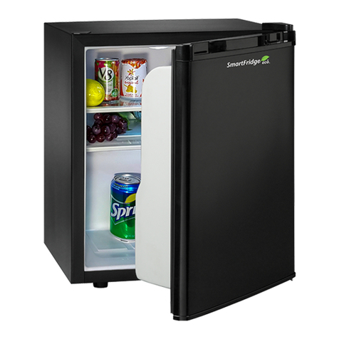
Minibar Systems SMARTCUBE SC-40T User manual

User Manual
Revised on 05/09/2022 Page 1
MINIBAR SYSTEMS
USER MANUAL
Installation Instructions,
Operating Instructions and
Case Good Specifications
Models: SC-40T and DualBar

User Manual
Revised on 05/09/2022 Page 2
4. Ventilation—Basic Principles and the SmartCube Environment 5
4.1 Inlet Ventilation 5
4.2 Shelf Cutout 6
4.3 Exhaust Ventilation 6
5. Cavity Opening for SmartCube Models 7
5.1
Insertable Cavity Opening
7
5.2
Snack Options
7
5.3
Door Options
11
5.4
Cable Holes (see Diagram B)
11
5.5 Diagram A – Cavity Opening 12
5.6 Level and Install 13
5.7
Diagram B – Cable Hole Placement for a Single Tray and Optional Electronic Lock
14
6. Temperature Regulation: 15
7. Enabling and Disabling Optional Lighting 15
8. Communications 16
9. Routine Maintenance and Cleaning 16
10. Installation Instructions 17
10.1 Door Shelf Replacement 17
10.2 Door Shelf Installation 20
10.3 SmartCube Shelf Replacement 22
10.4 Cube Shelf Installation 23
10.5 Console Box Replacement 24
10.6 Console Box Installation 25
10.7 Lock Override Enabled (when electronics malfunctions) 26
10.8 Lock Override Disabled (when electronics functions) 27
10.9 DualBar Installation 28
10.10 SmartCube Installation 31
11. Use, Safety, Recycling and Disposal 33
12. Minibar Systems Global Offices 34

User Manual
Revised on 05/09/2022 Page 3
Important Safety Instructions
WARNING
To reduce the risk of fire, electrical
shock, or injury when using your
appliance, follow these basic
precautions:
•Read all instructions before using your appliance.
•DANGER or WARNING: Risk of child entrapment.
•Before you throw away your old appliance: Take off the doors. Leave the
shelves in place so that children may not easily climb inside.
•Never allow children to operate, play with, or crawl inside this or any other
appliance.
•Never clean appliance parts with flammable fluids. The fumes can create a
fire hazard or explosion.
•Do not store explosive substances such as aerosol cans or use gasoline or
any other flammable propellants or liquids in the vicinity or in this or any
other appliance. The fumes can create a fire hazard or explosion.
•This appliance is intended to be used in household and similar applications
such as:
ostaff kitchen areas in shops, offices and other working environments;
ofarm houses and by clients in hotels, motels and other residential
type environments;
obed and breakfast type environments;
ocatering and similar non-retail applications.
•If the mains power cord is damaged, at any time, it must be replaced by
Minibar Systems, its service agent or similarly qualified person in order to
avoid a hazard.
•SmartCube is not intended for use by persons (including children) with
reduced physical, sensory or mental capabilities, or lack of experience and
knowledge, unless they have been given supervision or instruction
concerning use of the appliance by a person responsible for their safety.
Children should be supervised to ensure that they do not play with the
SmartCube.
•WARNING: To avoid a hazard due to instability of the appliance, it must be
fixed in accordance with the instructions
-Save these instructions-

User Manual
Revised on 05/09/2022 Page 4
These User Instructions are for guidance for all SmartCube model SC-40T and DualBar units available.
To obtain the best possible performance and trouble free operation for your SmartCube it is very important to
carefully read these instructions before user and observe the important safety information detailed.
1. Unpacking the SmartCube
•When unpacking the product, check for damage and missing parts. Damage in transit must be reported
immediately to the carriers and your Minibar representative.
•The SmartCube’s electronic service tray is not designed to bear weight. Do not stack SmartCube’s or
place heavy objects on top during transit to the guest room. Heavy objects would include items such as
a television, case good, etc.
•Dispose of the packaging in accordance with your local recycling ordinances.
2. Electrical Safety
• Before installation, check the following IMPORTANT items for ELECTRICAL SAFETY and to obtain the best
performance from your SmartCube.
• Before connecting the SmartCube to the mains power wall socket, verify the voltage stated on the
product rating plate (inside the cold cube) is the same as the mains voltage supplied to the wall socket.
• A standard AC mains outlet plug (socket) with safety ground is provided. The AC mains supply to the
SmartCube must be clean and stable.
• Make sure the mains power cord or any other cables are not trapped under the unit.
• If the mains power cord is damaged, at any time, it must be replaced by Minibar Systems, its service agent
or similarly qualified person in order to avoid a hazard.
• The use of an extension cord is not recommended.
• Minibar Systems cannot be held responsible if these measures are not observed.
3. FCC Statement:
This equipment has been tested and found to comply with the limits for a Class B digital device, pursuant to
part 15 of the FCC Rules. These limits are designed to provide reasonable protection against harmful
interference in a residential installation. This equipment generates, uses and can radiate radio frequency
energy, and if not installed and used in accordance with the instructions, may cause harmful interference to
radio communications. However, there is no guarantee that interference will not occur in a particular
installation. If this equipment does cause harmful interference to radio or television reception, which can be
determined by turning the equipment off and on, the user is encouraged to try to correct the interference by
one or more of the following measures:
•Reorient or relocate the receiving antenna.
•Increase the separation between the equipment and receiver.
•Connect the equipment into an outlet on a circuit different from that to which the receiver is connected.
•Consult the dealer or an experienced radio/TV technician for help.
User Manual
Revised on 05/09/2022 Page 5
Ventilation—Basic Principles and the SmartCube Environment
See recommendations in A, B, C, and D on how to achieve adequate ventilation.
Ventilation occurs by convection. Convection is the transfer of heat by
air currents. A cutout is required under the bar shelf for air circulation. It
allows air to rise up over the cooling unit and exhaust out of the cabinet
allowing for proper ventilation and performance of the SmartCube.
Minibar Systems would like to stress that proper ventilation for the SmartCube
is imperative to ensure maximum efficient operation of the cooling unit.
The SmartCube must not be placed against a heating radiator, window, direct
sunlight or curtains.
Visit https://smartcube.minibarsystems.com/downloads/
for most up to date ventilation specification
Inlet Ventilation
The inlet vent(s) must have a minimum of 31 in2(200 cm2) to
comply with specifications. This is based on a typical guest room
environment of 73º F (23º C) with a relative humidity of no more
than 80%. The vent can be provided in any of the following
configurations:
i) A cutout in the toe kick
ii) A series of slots in the toe kick
iii) A grill in the toe kick
iv) An arched opening in the toe kick

User Manual
Revised on 05/09/2022 Page 6
Shelf Cutout
The shelf is to be cut away directly below the cooling unit at 14.17”
(360 mm) from the back of the door. This must be a minimum open
area of 31 in2(200 cm2). This is important for maximum cooling
efficiency. The easiest way to accomplish the required ventilation is
to cut away the shelf across its complete width and extend the cut
out back to the rear of the case good.
Exhaust Ventilation
The exhaust vent(s) must have a minimum of 31 in2(200 cm2) to
comply with specifications. The vent can be provided in any of the
following configurations:
i) A series of slots in the top (see Option 1)
ii) A grill in the top (see Option 1)
iii) If the design will not permit the use of slots or grills, the unit
can be spaced 2” (50.8 mm) from the wall to allow exhaust.
It is recommended that spacers be used to prevent the case
good from being pushed against the wall. The underside of
the shelf above the SmartCube must be flat so no obstruction is caused to the airflow. In this
instance the back of the unit housing the SmartCube must
be cut away completely (see previous diagram Option 2).
The exhaust vent must exit into free space in the guest room. It
must not vent into an enclosed space such as a closet, case good or
ceiling void, as the heat will be trapped. The SmartCube must not be
placed against a heating radiator, window, direct sunlight or
curtains. Ventilation grills or slots must not be covered.
For more information, refer to the SmartCube Case Good
Specifications manual available from your Minibar representative or
from the Minibar Systems website.
Visit https://smartcube.minibarsystems.com/downloads/ for most up
to date ventilation specification
Option 1
Option
2
Ventilation
A minimum opening of
80 in2(517 cm2) for
Intake, Shelf Cutout
and Exhaust is required
for properventilation.
Exhaust
Intake
Shelf
Cutout
Option 2
Option 1

User Manual
Revised on 05/09/2022 Page 7
Cavity Opening for SmartCube Models
The physical cavity opening must be larger than the SmartCube to allow a minimum of 0.5” (12.7 mm) at
both sides and top. This will allow the SmartCube to be removed as needed and allows access to the top
cap for servicing.
If the case good spec is designed to have a lip it must not cover access to the minibar top cap for
servicing. If you have any questions, please consult Minibar Systems.
Please contact Minibar Systems for review of your case good drawings.
SmartCube Dimensions
Model
Height
Width
Depth*
SC-40
22.92”
582.4 mm
16.14”
410 mm
18.7”
475 mm
GF-27
22.92”
582.4 mm
12.2”
310 mm
18.7”
475 mm
DualBar
22.92”
582.4 mm
28.465”
723 mm
18.7”
475 mm
Insertable Cavity Opening
(see Diagram A in Section 4)
Height
Width
Depth*
SC-40
26.66”
677 mm
20.47”
520 mm
23.43”
595 mm
GF-27
26.66”
677 mm
16.532”
420 mm
23.43”
595 mm
DualBar
26.66”
677 mm
36.22”
920 mm
23.43”
595 mm
Snack Options
The SmartTray will generally be placed on top of the SmartCube, on a desk or credenza whereas
the ambient snack tray is mounted in a drawer or stationary/pull out shelf behind a case good
door. For general purposes, if the snack section is behind the case good door the minimum height
requirement is 8” (203.2 mm) with a divider wall 9.8” (248.92 mm) from the inside face of case
good door (see Diagrams A and B for cavity requirements). The internal color of this area must be
matt black or dark. If any variations are to be considered, please consult Minibar Systems for
further assistance.

User Manual
Revised on 05/09/2022 Page 8
SmartCube was designed to support unlimited external capacity for snack and sundry items the
hotel may wish to make available. If the hotel is using multiple SmartTrays or ambient snack trays,
please consult Minibar Systems for further assistance since hole requirements will vary. If a
SmartTray is used in a pull out shelf application, a separate rack is required to support products.
Black ambient snack trays come in the following configurations:
Snack Tray
Height
Width
Depth
4 sensors
.85”
21.59 mm
13”
330.2 mm
3.65”
92.71 mm
8 sensors
.85”
21.59 mm
13”
330.2 mm
6.3”
160.02 mm
10 sensors
.85”
21.59 mm
16.1”
409 mm
6.3”
160.02 mm
SmartTrays come in the following leatherette
(Short)
configurations:
SmartTray
Height
Width
Depth
2 sensor
Leatherette
2.25”
57 mm
8.875”
225.425 mm
4.8125”
122.2375 mm
4 sensor
Leatherette
2.25”
57 mm
14.8”
375.92 mm
4.8125”
122.2375 mm
8 sensor
Leatherette
2.25”
57 mm
14.8”
375.92 mm
8.0625”
204.787 mm
10 sensor
Leatherette
2.25”
57 mm
18.385”
467 mm
8.0625”
204.787 mm
SmartTrays come in the following leatherette
(Tall/Drawer)
configurations:
SmartTray
Height
Width
Depth
2 sensor
Leatherette
3.125”
79.38 mm
8.875”
225.425 mm
4.8125”
122.2375 mm
4 sensor
Leatherette
3.125”
79.38 mm
14.8”
375.92 mm
4.8125”
122.2375 mm

User Manual
Revised on 05/09/2022 Page 9
8 sensor
Leatherette
3.125”
79.38 mm
14.8”
375.92 mm
8.0625”
204.787 mm
10 sensor
Leatherette
3.125”
79.38 mm
18.385”
467 mm
8.0625”
204.787 mm
SmartTrays come in the following leatherette
(Wi-Fi)
configurations:
SmartTray
Height
Width
Depth
4 sensor
Leatherette
3.125”
79.38 mm
14.8”
375.92 mm
4.8125”
122.2375 mm
8 sensor
Leatherette
3.125”
79.38 mm
14.8”
375.92 mm
8.0625”
204.787 mm
10 sensor
Leatherette
3.125”
79.38 mm
18.385”
467 mm
8.0625”
204.787 mm
12 sensor
Flat Tray
Black wood
2.5”
63.5 mm
16.125”
409.57 mm
12.125”
307.97 mm
12 sensor
Tiered Tray
Black wood
Front
1.75” (44.45 mm)
Back
3.75” (95.25 mm)
16.5”
419.1 mm
16.125”
409.57 mm

User Manual
Revised on 05/09/2022 Page 10
SmartTrays comes in the following black wood configurations:
SmartTray
Height
Width
Depth
Single sensor
2.5”
63.5 mm
4.5”
114.3 mm
4.5”
114.3 mm
Two single sensors
2.5”
63.5 mm
9”
228.6 mm
4.5”
114.3 mm
4 sensor
Flat Tray
2.5”
63.5 mm
16.125”
409.57 mm
6.75”
171.45 mm
8 sensor
Flat Tray
1.875”
47.63 mm
16.5”
419.1 mm
9.625”
244.48 mm
12 sensor
Flat Tray
2.5”
63.5 mm
16.125”
409.57 mm
12.125”
307.97 mm
12 sensor
Tiered Tray
Front
1.75” (44.45 mm)
Back
3.75” (95.25 mm)
16.5”
419.1 mm
16.125”
409.57 mm

User Manual
Revised on 05/09/2022 Page 11
Door Options
The hotel can select from the following door options:
Solid Door
Glass Door
SC-40
GF-27
DualBar
Cable Holes (see Diagram B)
Diagram B shows the position of the cable holes drilled through the divider wall in the case good
if an optional electronic lock and/or ambient snack trays are installed. The diagram illustrates
drilling for both right-hand and left-hand hinged bars.
If the ambient snack tray is to be positioned on top of the case good surface or in a
stationary/pullout drawer, consult Minibar Systems for guidance and data cable routing.
Provisions must be made for the cable that runs from the SmartCube to the ambient snack tray.

User Manual
Revised on 05/09/2022 Page 12
Diagram A – Cavity Opening
Minibar
A‡*
B‡*
C
D
SC-40i
17.91”
455 mm
22.64”
575 mm
20.47”
520 mm
26.66”
677 mm
GF-27i
17.91”
455 mm
22.64”
575 mm
16.53”
420 mm
26.66”
677 mm
DualBar
17.91”
455 mm
22.64”
575 mm
36.22”
920 mm
26.66”
677 mm
Notes
•
All dimensions are internal
•
Placement of bar begins 0.5” (13 mm) inside the case good door
•
All tolerances 0.12” (3 mm)
•
*If the key is stored in the minibar lock, allow an additional 1.2” (30 mm)
•
8” (203.2 mm) recommended for height of ambient housing section for snacks
•
Please consult Minibar Systems if hotel is using 2 or more SmartTrays
•
The material covering the top of the Ambient Cavity should be matt black
•
The height of the Drawer bar cavity is 19
”
or 483 mm
•
Not to scale
D

User Manual
Revised on 05/09/2022 Page 13
Level and Install
•Before installation, check the surface where the SmartCube is to be placed. It MUST be solid, flat
and level.
•For optimum performance of the cooling system, it is recommended that the level is checked in
both planes – see the Level Diagram below.
• If it is not level, remedial action must be taken to level the surface.
•For safety, secure or anchor the SmartCube to the floor using screws appropriate for the material
and thickness of the case good floor. Holes can be found in each front foot and covers are provided
for aesthetic purposes.
•Ensure the mains power cord and any other cables are not trapped under the unit.
•For more information, refer to the SmartCube Case Good Specifications manual available from your
Minibar representative or from the Minibar Systems website.
Level Diagram
Typical level checks in both planes for optimum performance of the SmartCube. FRONT
VIEW SIDE VIEW

User Manual
2021 Page 14
Diagram B – Cable Hole Placement for a Single Tray and Optional Electronic
Lock
REFERENCE
HOLE DIAMETER
NUMBER OF HOLES
D1 – Optional Electronic Lock
5/8” (16 mm)
1
D2 – Ambient Snack Tray
5/8” (16 mm)
1
Left Hinge Bar
Right Hinge Bar
Notes
•
Dimensions are in inches and millimeters
•
*Depends on tray placement in cavity. Contact Minibar Systems for assistance.
•
See Section 3.3 if using multiple trays, hole placement may vary
•
All dimensions are internal
•
All tolerances 0.12” (3 mm)
•
Roller catches are not required if optional electronic lock is used
•
Not to scale
D1 Hole Placement
C
D
Horizontal Lock
0.79” (20 mm)
0.79” (20 mm)
Vertical Lock
0.4” (10 mm)
2.6” (65 mm)
D2 Hole Placement
A*
B
2x4 Tray
13.3” (338 mm)
0.4” (10 mm)
2x5 Tray
14.9” (378 mm)
0.4” (10 mm)
D1 Hole Placement
C
D
Horizontal Lock
0.79” (20 mm)
0.79” (20 mm)
Vertical Lock
.4” (10 mm)
3.1” (78 mm)
D2 Hole Placement
A*
B
2x4 Tray
13.3” (338 mm)
0.4” (10 mm)
2x5 Tray
14.9” (378 mm)
0.4” (10 mm)

User Manual
2021 Page 15
Temperature Regulation:
• The operating temperature of the SmartCube is subject to many factors: the correct and level
installation, proper ventilation, the internal product load,etc.
• The temperature control box is factory set for optimum performance for the SmartCube.
• For cooling adjustment, the temperature control box can be reset by moving the dial on the unit – see
the Temperature Adjustment Diagram below.
• The box is positioned on the back of the SmartCube.
• The cooling cycle has automatic defrost every 24 hours.
Temperature Adjustment Diagram
The factory setting can be adjusted by rotating the dial.
MAX is for maximum cooling.
Enabling and Disabling Optional Lighting
SmartCube has a standard exterior and interior lighting feature for Flexi and Automated models. The
intensity of the lighting is controlled via the S3 software and can be adjusted from an off position to level
10 as desired. This is a programmable feature set up during the installation of the SmartCubes at the
hotel. Classic model lights are not programmable. If the hotel requires the BLUE LEDs to be switched off,
there is an isolator switch fitted to the PCB at the front of the service tray. It can be set to the off
position.Enabling and Disabling Optional Lighting:
MIN
37.4°F/ 3°C
1
42.8°F/ 6°C
2
48.2°F/ 9°C
MED
53.6°F/ 12°C
3
59°F/ 15°C
4
64.4°F/ 18°C
MAX
71.6°F/ 22°C

User Manual
2021 Page 16
Communications
• Some SmartCube models have the ability to communicate to the Minibar Systems computer server via
an integral modem device.
• Internal data is gathered and then automatically communicated to the server.
• In addition, data can be transmitted to the SmartCube using a wireless hand held unit by the hotel.
This will also be automatically communicated to the server.
• The communications within the hotel will be set up by the Minibar Systems installation team in
coordination with the hotel and their network management team. The appropriate training will be
provided to the hotel personnel.
• For specific details on communication types, refer to the SmartCube Technical Specifications manual.
It is available from your Minibar representative or from the Minibar Systems website.
Note: See the Certification section regarding the FCC Statement for communications.
Routine Maintenance and Cleaning
• If the unit is fitted with an absorption cooling unit, it is recommended on an annual basis to check for
any leakage or small yellow type stains. If present, change the cooling unit. Please contact your
Minibar Systems representative for assistance.
• It is advisable to clean away any dust from the cooling unit and debris from the ventilation inlet and
exhaust vents, and shelf cutouts.
• For any other malfunction with the SmartCube, contact your Minibar Systems representative for
advice.
• Occasionally, it may be necessary to clean the inside of the SmartCube. For Classic and Flexi models,
simply use a soft damp clean cloth on the plastic surfaces. For the Automated model, it would be best
to do this during a refill operation while the SmartCube is offline for the refill. Alternatively, it will be
necessary to suspend the communications to the bar at the base station server prior to cleaning.
• It is important NOT to use too much water, strong chemicals, cleaning agents, soap or abrasive
cleaning materials.
• If appropriate, the outside of the SmartCube can also be wiped down using a soft damp clean cloth.

User Manual
2021 Page 17
Installation Instructions
These Installation Instructions are for guidance for all SmartCube models SC-40T units available.
Door Shelf Replacement
To remove the door-mounted shelf you will need to first
remove the rubber plug on the left side of the door shelf
column that is protecting the un-used backplane
connector.
Free the door racks from the plastic tab locking features
by squeezing onto the sides of the door shelf column.
Lift up on the door rack kit to release.

User Manual
2021 Page 18
The door rack will now be loose and able to slide out the
upper and lower door rack kit.
Un-screw the right side door shelf column using a Philips
head screw driver and remove the shelf column.

User Manual
2021 Page 19
Disconnect door sensor shelf from the backplane board
and the release engagement feature by sliding door
sensor shelf to the right.
Remove the sensor shelves for replacement.

User Manual
2021 Page 20
Door Shelf Installation
Slide the door sensor shelf (MB-MA-0035) into the
bottom support and connect it to the backpane
Screw the right side door shelf column using a Philips
head screw driver to secure the sensor shelves.
Slide the rack kit between the two door shelf columns
and engage into the side wall locking tabs.
This manual suits for next models
1
Table of contents
Other Minibar Systems Refrigerator manuals

Minibar Systems
Minibar Systems PT-27NFA Operation manual

Minibar Systems
Minibar Systems SmartFridge 50 User manual

Minibar Systems
Minibar Systems Primo XC-30-1 User manual

Minibar Systems
Minibar Systems SMART CUBE SC40T User manual

Minibar Systems
Minibar Systems SmartFridge 65 User manual

Minibar Systems
Minibar Systems SmartFridge User manual

Minibar Systems
Minibar Systems GuestFridge Slim User manual