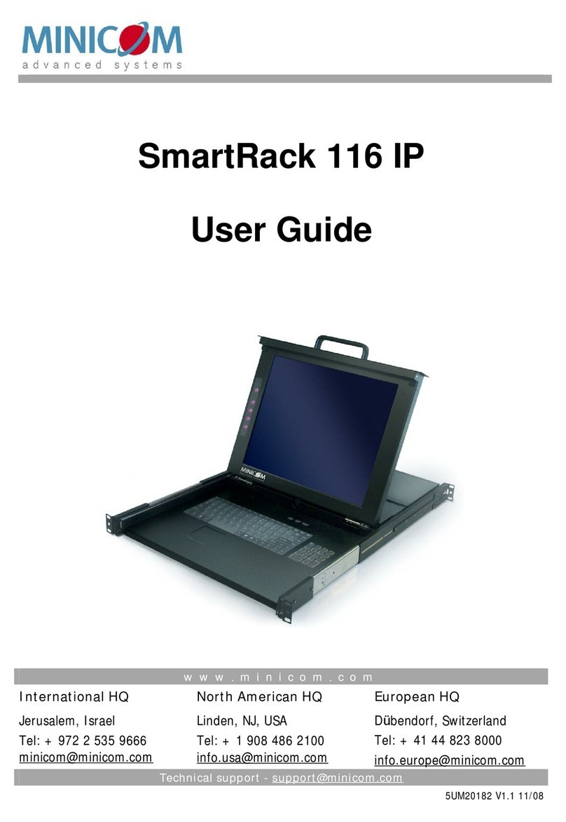
Minicom SmartRack User manual

www.minicom.com
InternationalHQ
Jerusalem,Israel
Tel:+9722535 9666
minicom@min
icom.com
NorthAmericanHQ
Linden,NJ,USA
Tel:+1908486 2100
info.usa@minicom.com
EuropeanHQ
Dbendorf,Switzerland
Tel:+4144823 8000
info.europe@minicom.com
Technicalsupport - support@minicom.com
5UM20180
V1
.111
/08
SmartRack
Quick Installation Guide

SMART
RACK
1
1
.Introduction
The
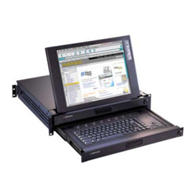
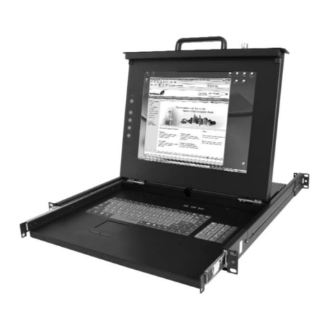
SmartRackfromMinicomisa slim, rackmountableconsoledrawer.The
SmartRack
canbeusedasa stand aloneunitorconnectedtoa 16 portKVMSwitchor
16
portKVMIPswitch. Occupyingjust1Uofrackspace, it’stheneat, space-saving
waytocontrolyourdatarack. Itcomeswithall thehardwareyouneedtomountit, and
iseasytoinstall.
Youcanaccess and controlup to16 multi
-platformcomputersfromoneKVM
(keyboardvideomouse
)console.
Toaccess
servers, justslideoutthedrawerand flipup itstoptodisplaythelarge, high
resolution
17”TFTLCDdisplay.
Thedisplayis
(VGA/SVGA/XGA/SXGAcompatible)withfront-panelhigh-quality
controls
and Touchpadforeasyadjustment. Whennotinuse, thekeyboardcanbe
concealedby
closingthetop.
2
.System components
The
SmartRacksystemcanconsistof:
SmartRack
consoledrawer(Standalone).
Or
SmartRackconsoledrawer+SmartRack116 Switch.
Or
SmartRackconsoledrawer+SmartRackSwitch116IP Switch.
3
.Hardware kitcontents
Rail withfrontand rearbracketx2,
forrackdepthof614 ~800 mm
.
Rightand left
sidesaredifferent.
Longbracketx2. (Forincreasedrack
depthof905 ~990mm)

QUICKINSTALLATIONGUIDE
2
Shortbracketx2
Bracketattachmentx2
Note!
Theshortbracketandbracketattachmentfora rackdepthof504~614 mmand
withouta KVMswitchconnectedtothedrawer.
Flatscrew
sx6(forrail mounttoconsolebody)
Screw
sx6
BracketAwiththumbscrewx2
Screws
x4
Keysx2.
4
.Avoidinggeneralrackmountingproblems
Elevatedoperatingambienttemperature
Theoperatingambienttemperatureoftherackenvironmentmaybegreaterthanthe
roomambientwheninstallingintoa closedormulti
-unit rackassembly. Soinstallthe
equipmentinanenvironmentco
mpatiblewiththemaximumratedambient
temperature.
Reducedairflow
Installtheequipmentina rackinsucha waythattheamountofairflowrequiredfor
safeoperationisnotcompromised.
Mechanicalloading
Mounttheequipmentintherackinsucha wayt
hatahazardousconditionisnot
achievedduetounevenmechanicalloading.
Circuitoverloading
Whenconnectingtheequipmenttothesupplycircuit, considertheeffectthat
overloadingofcircuitsmighthaveon over
-currentprotectionandsupplywiring.

SMART
RACK
3
Reliableearthingofrack
-mountedequipmentshouldbemaintained. Giveattentionto
supplyconnectionsotherthandirectconnectionstothebranchcircuit(e.g. useof
powerstrips).
5
.Connectingto arack
Note!
Forincreasedrackdepthof905 ~990mm,firstchangethebracket, see
section
6 onpage5.
Note!Theillustrationsbelowshowtheconnectionsto
onesideoftheSmartRack.The
connectionsarethesameforthe
otherside.
1
.Movetherail until twoscrewsappear,seeFigure1.
Figure1Exposing the2screws
2
.Loosenslightlythe7screwsasshownbelow.
Figure2Loosen7screws
3
.Adjusttherearbrackettofityourcabinet, seebelow.
Figure3Adjusting thebracket
4
.Installthefrontand rearbracketontothecabinet, seefigurebelow.

QUICKINSTALLATIONGUIDE
4
Figure4Installing frontand rearbracketon cabinet
5
.Tightenthe7screwsasshownbelow.
Figure5Tightening the7screws
6
.Repeatthestepsabovetoconnecttheotherrail totheothersideoftherack.
7
.SlidetheSmartRackconsolebetweentherailsasshownbelow.
Figure6Sliding theSmartRackbetweentherails
8
.Unlockandpull bothleftand rightrail–lockswitchestogether–seebelow–and
pushtheconsoleallthewayintotherack.

SMART
RACK
5
Figure7Rail–lockswitch
9
.Connectthreeflatscrewstotherearoftheconsoleon bothsides. Seefigurebelow.
Figure8Connecting threeflatscrewstotherearoftheconsole
The
consolenowsitssnuglyintherack, seeFigure9.
Figure9Consoleintherack
6
.Usingthe longerbracketforrackdepthof905 ~990mm
Toreplacethebracketwiththelongerbracket:
1
.Loosenthe7screwsasshownbelow.

QUICKINSTALLATIONGUIDE
6
Figure10 Loosening the7screws
Removethesix(different)screwsasshownbelow.
Figure11 Removing thesixscrews
2
.Taketherearbracketout, seebelow.
Figure12 Taking therearbracketout
3
.Insertthelongbracketintotherail thenadjustthebrackettofityourcabinet.
Tightenatleast2~3screwsalongthelengthyouneed.SeeFigure13.
Figure13 Inserting and tightening thelong bracket
4
.Repeattheabovestepsfortheotherside.

SMART
RACK
7
5
.Gotosection 5Connecting toa rack.
7
.Connectingthe Switch116or 116IP
1
.ConnectthebracketAtothesidesoftheSwitchusingthetwo6mmscrews
providedseefigurebelow.
Figure14 Connecting thebracketAto thesidesoftheSwitch
2
.SlidetheSwitch116 intotherail and intothebackoftheSmartRackconsoleuntil
youhearaclick. Seethefigurebelow.
Figure15 SlideswitchintobackofSmartRack
3
.SecuretheSwitch116 totherail byinsertingthethumbscrewsthroughthebracket
and intotherail and tighteningthem, seeFigure16.
Figure16 Tightening thethumbscrews

QUICKINSTALLATIONGUIDE
8
8
.Pre-installationguidelines
•
Switchoff all computers
•
Placecablesawayfromfluorescentlights,airconditioners, and machinesthatare
likelytogenerateelectricalnoise
•
Ensurethatthemaximumdistancebetweeneachcomputerand theSmartRack
Switch, doesnotexceed10m/33ftforRICCsand 30m/100ftforROCs
9
.The SmartRackSwitchsystem configuration
Youconnectserverstothe
116 and 116IP switchesvia ROCsorRICCs.Figure17
and
Figure
18 illustratethebasicconfigurationofthe116 and116IP system.
123456 78
10 11 12 13 14 15 169
MINICOM
Toservers
M I NIC OM
ROC/RICCs
toservers
CAT5cables
Upto10M/ 33ft
I
0
SMARTRACK116 SWITCH
SMARTRACK 116SWITCH
Figure17 SmartRack116Switchsystem configuration

SMART
RACK
9
12345678
10 11 12 13 14 15 169
MINICOM
I
0
SMARTRACK116IPSWITCH FLASH LAN
SERIAL
Toservers
MINIC O M
ROC/RICCs
toservers
CAT5cables
Upto10M/ 33ft
UseroverIP
Internet/VPN/ LAN
SMARTRACK116IPSWITCH
Figure18 SmartRack116IPSwitch systemconfiguration
10
.The 116and116IPswitches
1 2 3 4 5 6 7 8
10 11 12 13 14 15 169
MINICOM
I0
SMARTRACK116SWITCH
Power
connector
Serverports
Download
connector
Figure19 116 Switch ports
Connector
table
Connector
Function
Download
ToupdatefirmwareoftheOSD, Switch,RICCsandROCS.
Serverports
ConnecttoserversviaROC/RICCs

QUICKINSTALLATIONGUIDE
10
Power
connector
Serverports
LAN(Ethernet)
connector
Flash
(download)
connector
1 2 3 4 5 6 7 8
10 11 12 13 14 15 169
MINICOM
I0
SMARTRACK116IPSWITCH FLASH LAN
SERIAL
Figure20 116IPSwitchports
Connector
table
Connector
Function
Serial
ThisportisforfutureSerialfunctionality
Flash
Toupdatefirmwareoftheanaloguepartof the116 IPSwitch
system-OSD,Switch,RICCsandROCs.
LAN
Connectto10/100MbitEthernet. YellowLedilluminateswhen
connectedtoLAN.GreenLEDilluminateswhenaremotesession
isinprogress
Serverports
ConnecttoserversviaROC/RICCs

SMART
RACK
11
11
.ConnectingROCor RICC to servers
Eachcomputer/serverisdirectlyconnectedtothe
SmartRackswitchvia the
appropriate
ROCorRICCusing CAT5cableina starconfiguration.Thesystemcan
containa mixtureofROCsand RICCs.
Noexternalpowerisneededattheremote
ROC
/RICCs.TheROC/RICCsdrawtheirpowerfromthecomputer’skeyboardport
(
ROC/RICCPS/2)orfromtheUSBport(ROC/RICCUSB). Thefiguresbelow
illustratetheROCPS/2a
nd ROCUSB.
Tocomputer’s
keyboardport
Tocomputer’s
mouseport
Tocomputer’s
Video card
Figure21 ROCPS/2
Tocomputer’s
USB Port
Tocomputer’s
Video Card
Figure22 ROCUSB(SUN)
ConnectingaROC/RICC
PS/2
Theconnectionsfor
ROC/RICCPS/2areexactlythesame. Figure23 illustratesthe
RICC
PS/2.
YoucanconnecttheROC/
RICC PS/2toa poweredoncomputer, butitmustbeinthe
followingorder:
1
.ConnecttheMouseconnectortothecomputer’sMouseport.
2
.ConnecttheKeyboardconnectortothecomputer’sKeyboardport.
3
.ConnecttheScreenconnectortothecomputer’sVideoport.
Failuretoconnect
intheaboveorderwhiletheserverisrunning,mayleadtothe
mouse
malfunctioninguntiltheserverisrebooted.

QUICKINSTALLATIONGUIDE
12
ToKeyboardport
CAT5cabletoSwitch
Computerport
ToMouseport
ToVideo port
RICC
K e y b d
M o u s e 1 0 0 T
V i d e oS e r i a l A
P a r a l l e l
PCI33Mx32b
PCI33Mx32b
PCI33Mx32b
PCI33Mx32b
S eri a l B
NetServertc2100
SCSI
Figure23 RICC PS/2connections
Connectinga
ROC/RICC USB
The
ROC/RICC USBsupportsWindows98 SEand later, MAC,SUN, SGIand all
modernLinux distributions
.TheconnectionsforROC/RICCUSBareexactlythe
same.
Figure24 illustratestheRICC USBand itsconnections.
Toconnectthe
ROC/RICCUSB:
1
.ConnecttheScreenconnectortothecomputer’sVideoport.
2
.ConnecttheUSBconnectortothecomputer’sUSBport.
ToUSB Port
ToVideoport
CAT5cabletoSwitch
Computerport
RICC USB
Figure24 RICCUSB

SMART
RACK
13
12
.Connectingthe CAT5cables
1
.ConnectoneconnectortotheROC/RICC’sRJ45 port.
2
.ConnecttheotherconnectortooneoftheSmartRackSwitchServerports.
3
.Followtheabove2stepsforeachcomputer.
13
.Connectingto the network
Forthe
SmartRack116IPSwitch, connectthenetworkcabletotheLANport.This
mustbedonebeforepoweringonthe
SmartRack116IPSwitch.
14
.Connectingthe power supply
1
.ConnecttheswitchtothepowersupplyusingthePowercordprovided. Onlyuse
thePowercordsuppliedwiththeunit.
2
.Powerontheswitchandthecomputers.
15
.OperatingtheSmartRackSwitchsystem
Forthe
SmartRack116 switchgototheSmartRack116 switchOperatingGuide.
Forthe
SmartRack116IPswitchgototheSmartRack116IP switchOperatingGuide.
©2008MinicomAdvancedSystemsLimited. Allrightsreserved.

QUICKINSTALLATIONGUIDE
14
RegionalOffices
Germany
Kiel
Tel:+49 431 668 7933
info.minicom
-germany@minicom.com
France
Vincennes
Tel:+33 14957 00 00
info.france@minicom.com
Italy
Rome
Tel:+39 068209 7902
info.italy@minicom.com
England
Tel:+44 121 288 06
08
info.uk@minicom.com
China
Beijing
Tel:+862164453181
Info.china@minicom.com
AsiaPacific/S.Korea
Tel:+97225359618
info.ap@minicom.com
www.minicom.com
Table of contents
Other Minicom LCD Drawer manuals
Popular LCD Drawer manuals by other brands

Rose electronics
Rose electronics Rackview LCD Panel Mount 19" Installation and operation manual

HAMPTON BAY
HAMPTON BAY HD-SDUS-121 Use and care guide

I-Tech
I-Tech XELD115e Specifications

Tripp Lite
Tripp Lite B021-SWHD-K quick start guide

Black Box
Black Box KVT217A manual

Tripp Lite
Tripp Lite B021-000-17 owner's manual