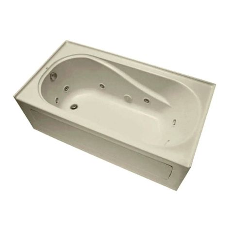
Mirabelle Bradenton MIRBDA6032 Manual

INSTALLATION & OPERATING
INSTRUCTIONS FOR LUXURY BATHTUBS
SAVE THIS MANUAL: RETAIN FOR CONSUMER’S USE. READ THESE INSTRUCTIONS COMPLETE-
LY BEFORE INSTALLING THE PRODUCT: FOR PRODUCT OR INSTALLATION QUESTIONS PLEASE
CALL CUSTOMER SERVICE AT 1-800-221-3379.
YOU MUST FOLLOW ALL INSTRUCTIONS IN THIS MANUAL: FAILURE TO DO SO WILL RESULT IN
YOUR ASSUMPTION OF LIABILITY AND WILL VOID WARRANTY AND CAN RESULT IN PRODUCT
DAMAGE OR PERSONAL INJURY.
FAILURE TO USE A SUITABLE SETTING COMPOUND WILL VOID THE WARRANTY.
THIS PRODUCT IS DESIGNED TO BE INSTALLED BY A LICENSED TRADESMEN.
LICENSED PLUMBERS AND ELECTRICIANS SHOULD BE EMPLOYED TO INSURE PROPER INSTAL-
LATION. INSTALLERS ASSUME ALL LIABILITY FOR THE CORRECT INSTALLATION PROCEDURES.
Only accessories authorized by the manufacturer should be used with this product.
This product is designed for residential use and use by healthy individuals.
IMPORTANT SAFETY INSTRUCTIONS: WARNING!
WHEN USING THIS PRODUCT, BASIC PRECAUTIONS SHOULD ALWAYS BE FOLLOWED. READ
AND FOLLOW ALL INSTRUCTIONS PERTAINING TO RISK OF FIRE, ELECTRIC SHOCK, OR INJURY
TO PERSONS.
Installer: Leave this manual for homeowner.
Homeowner: Read this manual and keep for future reference.
Distributed Exclusively by Ferguson and Wolseley Canada
© 2015 Ferguson Enterprises, Inc. All Rights Reserved 25670 05/15
FIVE YEAR LIMITED WARRANTY
All Mirabelle Whirlpools and Bathing Systems are warranted in accordance with the following Limited
Warranty: Mirabelle Whirlpools and Bathing Systems are warranted against defects in material and
workmanship for a period of five (5) years from the date of the first consumer purchase. This Warranty shall
apply to defective acrylic surfaces which crack, fade or blister, and any defect in whirlpool and bathing
system components. The Warranty extends to the first consumer purchaser and not to subsequent owners,
transferees or users other than the first purchaser.
This warranty does not extend to products previously utilized as display models. This Warranty shall apply
to products installed and used only for personal, family or household purposes and which are installed
and maintained in accordance with Mirabelle Whirlpool and Bathing Systems’ recommended installation
and maintenance procedures. This Warranty does not extend to defects or damage caused, in whole or
in part, by any unauthorized or unreasonable use.
No liability shall exist for incidental or consequential damages caused in whole or part by any defects in
Mirabelle Whirlpools and Bathing Systems. No warranty, expressed or implied, including any warranty of
merchantability or fitness for a particular purpose, shall apply after the warranty period described above.
Some states do not allow the exclusion or limitation of incidental or consequential damages or limitations
on how long an implied warranty lasts. The above limitation may not apply to you.
In the event of a defect in material or workmanship of a Mirabelle Whirlpool or Bathing System during
the Warranty period, defective products will be repaired or replaced as Mirabelle, at its sole and absolute
discretion, determines. However, Mirabelle shall not be liable for the expense for removing defective
products or installing replacement products. In certain circumstances, some states do not allow the
limitation of liability for removal, transportation and reinstallation expenses. The above limitation may not
apply to you.
Only Mirabelle is authorized to perform its warranty obligation. If you wish to obtain performance of the
Mirabelle warranty obligation you should contact Mirabelle, at (800) 221-3379. Other information about
performance of the Mirabelle Whirlpool and Bathing Systems’ warranty obligation may be obtained at the
same address and telephone number.
This Warranty gives you specific legal rights and you may also have other rights which vary from state to
state.

IMPORTANT SAFETY INSTRUCTIONS
INSTRUCTIONS PERTAINING TO A RISK OF FIRE,
ELECTRIC SHOCK OR INJURY TO PERSONS
READ AND FOLLOW ALL INSTRUCTIONS!
WARNING: Risk of personal injury.Do not permit children to use this unit without adult supervision.
WARNING: Risk of personal injury.Do not operate this unit without the guard over the suction fitting.
WARNING: Risk of electric shock.Do not permit electrical appliances (hair dryer, telephone, radio, etc.) within 60
inches (1524mm) of this unit.
WARNING: Risk of hyperthermia and possible drowning.People using medications and/or having adverse
medical history should consult a physician before using this product.
WARNING: Risk of personal injury.Do not overfill unit before entering. Entering tub when filled more than 2/3
can cause overflow and slippery conditions. Exercise caution when entering and exiting.
WARNING: No Food or Alcoholic Beverages.Use of your bathtub immediately after meals is not recommended.
Avoid alcohol consumption before or during bathing. Alcoholic beverages can cause drowsiness or hyperthermia
resulting in loss of consciousness or even drowning.
WARNING: Pregnancy.If you are or think you may be pregnant, consult your physician before using the bathtub.
Never drop or insert any object into any opening.
Use this unit only for its intended use as described in this manual. Do not use any attachments not recommended by
Mirabelle.
The unit must be connected only to a supply circuit that is properly protected by a ground-fault circuit-interrupter (GFCI).
Such a GFCI should be provided by the installer and should be tested on a routine basis. To test the GFCI, push the test
button. The GFCI should interrupt power. Push the reset button. Power should be restored. If the GFCI fails to operate in
this manner, the GFCI is defective. If the GFCI interrupts power to the bathtub without the test button being pushed, a
ground current is flowing, indicating the possibility of an electric shock. Do not use this hydromassage bathtub. Disconnect
the hydromassage bathtub and have the problem corrected by a licensed electrician before using.
A pressure wire connector is provided on the exterior of the motor unit to permit connection of a no. 8 AWG solid copper
bonding conductor between this unit and all other electrical equipment and exposed metal in the vicinity, as needed to
comply with local requirements. To reduce the risk of an electric shock, connect this connector to the grounding terminal
of your electric service or supply panel with a conductor equivalent in size to the circuit conductors supplying this unit.
15

Installation and Framing Instructions
Each bath arrives ready for installation, completely equipped with the pump and plumbing necessary
for operation. However, a drain/overflow kit is required for each bath and it is not included.
The variety of installations for this bath may require framing procedures other than those shown.
Locate studs as required. Ensure roughing-in dimensions are proper, plumb, and square.
Installation and Framing Instructions
Remove the bath from the carton. Retain the shipping carton until satisfactory inspection of the
product has been made. Do not lift the bath by the plumbing at any time; handle by the shell only.
All bath units are factory tested for proper operation and watertight connections prior to
shipping. Prior to installation and before enclosing with wallboard, tile, etc., the bath must be
filled with water and operated to check for leaks that may have resulted from shipping damage
or mishandling.
The sumps of these baths are not supported by the feet and additional sump support is required.
Motar (not cement) is recommended as support material. Once the bath is in place, the rim of the
bath should contact the stringer or pier but supports no weight.
Provisions must be made in all installations for an access opening for servicing the bath pump.
Unless an access opening of at least 12” x 24” (305mm x 610mm) is provided, warranty service
will not be performed. It is strongly recommended that an additional opening be provided for
access to drain components.
Each bath has a nominal length (L), width (W), and Height (H) along with a rim height. Unless
otherwise noted in the following rough-in references, assume that the nominal tolerances are
as much as +/-1/4 inch (6mm). Therefore, it is strongly recommended that the installer build the
surrounding structure after receiving the actual bath. Structural measurements should be verified
against the actual bath received to ensure proper fit.
POST INSTALLATION CLEAN-UP
Remove all construction debris from bath. Tile grout can be removed with a wooden popsicle stick or
tongue depressor.
Do not use wire brushes or any other metal implement on bath surface.
Post installation clean-up generally can be completed using warm water and liquid dishwashing
detergent.
Stubborn dirt or stains may be removed using granular Spic and Span® mixed with water. Painter’s
naphtha can be used to remove excess adhesives and/or wet oil-base paint.
FOR UNDER MOUNT TUB
FOR DROP IN TUB
14
WHIRLPOOL & TUB CUT OUTS

INSTALLATION AND FRAMING INSTRUCTIONS
The variety of installations possible for this whirlpool may require framing procedures other than those shown. Locate
studs as needed. Ensure roughing-in dimensions are proper, plumb and square. Provisions must be made in all
installations for an access opening for servicing the pump and controls. It is strongly recommended that an additional
opening be provided for access to the drain components. The apron should not be used as the primary access opening.
1. Position the whirlpool into the installation opening and level the deck in both directions, shimming the integral
leveling feet if necessary. Mark the final position of the underside of the deck by tracing a line on to the studs (see
Figure 1).
2. Remove the whirlpool and attach a 1 x 4 stringer to the studs, with the top of the stringer touching the traced line.
The rim of the bath must not support weight.
3. Install drain components to the whirlpool following the drain installation
instructions. Before replacing your whirlpool for final installation, be certain
that an opening has been provided in the sub-floor for the drain. See the
roughing-in drawing and Table 1 for suggested opening size (shadowed)
and location dimensions. The drain/overflow of the bath extends below the
bottom of the bath. Note that this requires a cutout in the floor.
The floor structure beneath the bath must be able to support a total
weight of bath, water, and bather. Refer to Table 1 under total weight
for your model.
The bath must be supported along its entire bottom. Use mortar as
bedding material (do not use sand or foam). Apply enough mortar to
support the complete bottom of the bath. After the mortar has been
poured, and before it sets, position whirlpool or bath within recess until
the rim is leveled against the leveling stringers (see “Typical Alcove
Installation”) shown below.
The rim of the bath must not support weight. Allow the mortar material
to completely harden before applying weight to the rim or bottom
of the bath. Any finish material such as tile or wall board must be self-
supporting if it contacts the deck of the bath.
INSTALLATION AND FRAMING INSTRUCTIONS
The variety of installations possible for this whirlpool may require framing procedures other than those shown. Locate studs as
needed. Ensure roughing-in dimensions are proper, plumb and square. Provisions must be made in all installations for an access
opening for servicing the pump and controls. It is strongly recommended that an additional opening be provided for access to the
drain components. The apron should not be used as the primary access opening.
1. Position the whirlpool into the installation opening and level the deck in both directions, shimming the integral leveling feet if
necessary. Mark the final position of the underside of the deck by tracing a line on to the studs (see Figure 1).
2. Remove the whirlpool and attach a 1 x 4 stringer to the studs, with the top of the stringer touching the traced line.
The rim of the bath must not support weight.
3. Install drain components to the whirlpool following the drain installation instructions.
Before replacing your whirlpool for final installation, be certain that an opening has
been provided in the sub-floor for the drain. See the roughing-in drawing and
Table 1 for suggested opening size (shadowed) and location dimensions. The
drain/overflow of the bath extends below the bottom of the bath. Note that this
requires a cutout in the floor.
The floor structure beneath the bath must be able to support a total weight of bath,
water, and bather. Refer to Table 1 under total weight for your model.
The bath must be supported along its entire bottom. Use mortar as
bedding material (do not use sand or foam). Apply enough mortar to support
the complete bottom of the bath. After the mortar has been poured, and before
it sets, position whirlpool or bath within recess until the rim is leveled against
the leveling stringers (see "Typical Alcove Installation") shown below.
The rim of the bath must not support weight. Allow the mortar material to
completely harden before applying weight to the rim or bottom of the bath. Any
finish material such as tile or wall board must be self-supporting if it contacts
the deck of the bath.
4
!
!
!
FIGURE 1
E
C
16
(406.4 mm)
16
(406.4 mm)
G
CUTOUT
C
F
CUTOUT
AS DESIRED
20
(508 mm) 20
(508 mm)
W
D
LEVELING
STRINGERS
ACCESS PANEL MUST BE LOCATED
ON THE SAME SIDE AS THE MOTOR.
ALLOW OPEN FRAMING ON
PUMP/MOTOR END FOR SERVICE.
ACCESS PANELS NOT REQUIRED
FOR BATH TUBS.
ACCESS PANEL MUST BE LOCATED
ON THE SAME SIDE AS THE MOTOR.
ALLOW OPEN FRAMING ON PUMP/MOTOR
END FOR SERVICE.
TILE
BEAD
STRIP
BATH
SEALANT
WATERPROOF
SEALANT
BATH
MOUNTING
SURFACE
AS DESIRED
LEVELING STRINGER
1 x 4 (not for support)
TILE
WALLBOARD
NOTE: Tile bead kit not included and
must be purchased separately.
C*
TYPICAL INSTALLATION
ADHESIVE
TYPICAL ALCOVE INSTALLATION TYPICAL DROP-IN TYPE INSTALLATION
UNLESS AN ACCESS OPENING OF AT LEAST 16" X 20"
IS PROVIDED, WARRANTY SERVICE WILL NOT BE PERFORMED. UNLESS AN ACCESS OPENING OF AT LEAST 16" X 20"
IS PROVIDED, WARRANTY SERVICE WILL NOT BE PERFORMED.
NOTE:
FRONT EDGE
OF BATH MUST
BE SUPPORTED
BY STUD WALL
WHIRLPOOL & TUB CUT OUTS
13
INSTALLATION AND FRAMING INSTRUCTIONS
The variety of installations possible for this whirlpool may require framing procedures other than those shown. Locate studs as
needed. Ensure roughing-in dimensions are proper, plumb and square. Provisions must be made in all installations for an access
opening for servicing the pump and controls. It is strongly recommended that an additional opening be provided for access to the
drain components. The apron should not be used as the primary access opening.
1. Position the whirlpool into the installation opening and level the deck in both directions, shimming the integral leveling feet if
necessary. Mark the final position of the underside of the deck by tracing a line on to the studs (see Figure 1).
2. Remove the whirlpool and attach a 1 x 4 stringer to the studs, with the top of the stringer touching the traced line.
The rim of the bath must not support weight.
3. Install drain components to the whirlpool following the drain installation instructions.
Before replacing your whirlpool for final installation, be certain that an opening has
been provided in the sub-floor for the drain. See the roughing-in drawing and
Table 1 for suggested opening size (shadowed) and location dimensions. The
drain/overflow of the bath extends below the bottom of the bath. Note that this
requires a cutout in the floor.
The floor structure beneath the bath must be able to support a total weight of bath,
water, and bather. Refer to Table 1 under total weight for your model.
The bath must be supported along its entire bottom. Use mortar as
bedding material (do not use sand or foam). Apply enough mortar to support
the complete bottom of the bath. After the mortar has been poured, and before
it sets, position whirlpool or bath within recess until the rim is leveled against
the leveling stringers (see "Typical Alcove Installation") shown below.
The rim of the bath must not support weight. Allow the mortar material to
completely harden before applying weight to the rim or bottom of the bath. Any
finish material such as tile or wall board must be self-supporting if it contacts
the deck of the bath.
4
!
!
!
FIGURE 1
E
C
16
(406.4 mm)
16
(406.4 mm)
G
CUTOUT
C
F
CUTOUT
AS DESIRED
20
(508 mm) 20
(508 mm)
W
D
LEVELING
STRINGERS
ACCESS PANEL MUST BE LOCATED
ON THE SAME SIDE AS THE MOTOR.
ALLOW OPEN FRAMING ON
PUMP/MOTOR END FOR SERVICE.
ACCESS PANELS NOT REQUIRED
FOR BATH TUBS.
ACCESS PANEL MUST BE LOCATED
ON THE SAME SIDE AS THE MOTOR.
ALLOW OPEN FRAMING ON PUMP/MOTOR
END FOR SERVICE.
TILE
BEAD
STRIP
BATH
SEALANT
WATERPROOF
SEALANT
BATH
MOUNTING
SURFACE
AS DESIRED
LEVELING STRINGER
1 x 4 (not for support)
TILE
WALLBOARD
NOTE: Tile bead kit not included and
must be purchased separately.
C*
TYPICAL INSTALLATION
ADHESIVE
TYPICAL ALCOVE INSTALLATION TYPICAL DROP-IN TYPE INSTALLATION
UNLESS AN ACCESS OPENING OF AT LEAST 16" X 20"
IS PROVIDED, WARRANTY SERVICE WILL NOT BE PERFORMED. UNLESS AN ACCESS OPENING OF AT LEAST 16" X 20"
IS PROVIDED, WARRANTY SERVICE WILL NOT BE PERFORMED.
NOTE:
FRONT EDGE
OF BATH MUST
BE SUPPORTED
BY STUD WALL

5
Illustration B
AIR MASSAGE CIRCUIT
Illustration C
WHIRLPOOL CIRCUIT
Illustration D
BRADENTON & PROVINCETOWN TOTAL MASSAGE
CIRCUIT WITH OPTIONAL WATER HEATING ELEMENT
TOTAL MASSAGE CIRCUIT WITH OPTIONAL HEATER
Illustration F
BRADENTON & PROVINCETOWN
AIR BATH CIRCUIT
Illustration A
Illustration E
Mirabelle Electrical Requirements
1. ALL CONNECTIONS MUST BE GFCI (Ground Fault Circuit Interrupted) PROTECTED
2. Whirlpool, Air Baths, and Total Massage units require dedicated 20 amp, 120 volt service.
3. You must provide a receptacle with a 20 amp configuration.
4. See local codes for proper wire size, if not specified, use #12 Copper only wire.
5. Use of an optional heater requires its own dedicated 20 amp service.
PUMP/MOTOR
BRADENTON & PROVINCETOWN WHIRLPOOL
WITH INSTALLED AIR SWITCH
Mirabelle Electrical Requirements
1. ALL CONNECTIONS MUST BE GFCI (Ground Fault Circuit Interrupted) PROTECTED
2. Whirlpool, Air Baths, and Total Massage units require dedicated 20 amp, 120 volt service.
3. You must provide a receptacle with a 20 amp configuration.
4. See local codes for proper wire size, if not specified, use #12 Copper only wire.
5. Use of an optional heater requires its own dedicated 20 amp service
12
WHIRLPOOL & TUB CUT OUTS
WHIRPOOL AND TUB CUT OUTS
66.000
RECESS MOUNT LINE: CUT ALONG LINE FOR RECESS MOUNT INSTALLATION
FLUSH MOUNT LINE: CUT ALONG LINE FOR FLUSH MOUNT INSTALLATION
4.500
57.125
Mirabelle: Cut Out Template
Use for Edenton 6636
Scale 1:1 0.250
4.375
18.000
14.500
3.250
WHIRPOOL AND TUB CUT OUTS
60.000
RECESS MOUNT LINE: CUT ALONG LINE FOR RECESS MOUNT INSTALLATION
FLUSH MOUNT LINE: CUT ALONG LINE FOR FLUSH MOUNT INSTALLATION
4.375
51.125
Mirabelle: Cut Out Template
Use for Edenton 6036
Scale 1:1 0.250
4.25
18.000
14.500
3.250
WHIRPOOL AND TUB CUT OUTS
60.000
RECESS MOUNT LINE: CUT ALONG LINE FOR RECESS MOUNT INSTALLATION
FLUSH MOUNT LINE: CUT ALONG LINE FOR FLUSH MOUNT INSTALLATION
2.875
52.625
Mirabelle: Cut Out Template
Use for Edenton 6032
Scale 1:1 0.250
3.50
16.000
13.000
2.75
Drain
Drain
Drain

“L”
LENGTH
“W”
WIDTH
“D”
HEIGHT
TO DECK
“B”
DRAIN
LOCATION
“A”
DRAIN
LOCATION
“H”
HEIGHT
TO LIP
Illustration F
Deck to floor dimensions are measured through the
drain hole to give a more consistent measurement.
The dimensions were achieved by laying a straight
edge across the deck, and then the distance from
the floor at the drain opening to the bottom of the
straight edge was measured. See illustration G. The
lip height is then subtracted to give a more
consistent floor to lip height. There may be height
dimension variations of +/ - 1/4" from the stated
dimension in the table, which is a standard
production tolerance.
IN LINE HEATERS ALWAYS REQUIRE THEIR OWN DEDICATED 20 AMP, 120 VOLT, GFCI PROTECTED CIRCUIT.
1. To install an in-line heater, simply unscrew the unions and remove the blank. The threaded pieces should remain on both
sides of the pipe section.
2. Insert the in-line heater and tighten the unions of the in-line heater to the remaining threaded portion of the heater blank.
The unit must be connected to a circuit interrupter (GFCI). Such a circuit is provided by the installer and should be tested on
a routine basis. To test the GFCI push the test button. The GFCI should interrupt power. Push the RESET button. Power
should be restored. If the GFCI fails to operate in this manner, there is ground current flowing, indicating the possibility of an
electrical shock. Do not use this unit. Disconnect the unit and have the problem corrected by a qualified service representative
before using.
6
Illustration G
Illustration H
MODEL
SEE ILLUSTRATION F
MIRBDA6032, MIRBDS6032, MIRBDT6032, MIRBDW6032 60" 32" 20" 18-1/2" 11" 16"
MIRBDA6032(LorR),MIRBDS6032(LorR),MIRBDT6032(LorR), MIRBDW6032(LorR) 60" 32" 21" 20" 11" 16"
MIRBRA6640V, MIRBRS6640V, MIRBRT6640V, MIRBRW6640V 66" 40" 22" 20-1/2" 33" 7 1/2"
MIRBRA7242V, MIRBRS7242V, MIRBRT7242V, MIRBRW7242V 71-1/2" 42" 22" 20-1/2" 35-3/4" 10"
MIREDA6030(LorR), MIREDS6030(LorR), MIREDW6030(LorR) 59-3/4" 29-3/4" 19-1/8" 19" 7-1/2" 15"
MIREDA6032(LorR), MIREDS6032(LorR), MIREDW6032(LorR) 59-3/4" 31-3/4" 19-1/2" 18-1/16" 8-3/4" 15-3/4"
"61"4/3-7"81"2/1-91"8/7-13"4/3-952306WDERIM,2306SDERIM,2306ADERIM
MIREDA6036, MIREDS6036, MIREDT6036, MIREDW6036 59-3/4" 35-3/4" 22-1/4" 20-3/4" 9-1/4" 17-3/4"
MIREDA6636, MIREDS6636, MIREDT6636, MIREDW6636 66" 36" 22-1/2" 21" 11" 18"
MIREDA7236, MIREDS7236, MIREDT7236, MIREDW7236 71-1/2" 35-3/4" 23-3/4" 21-3/4" 9-1/4" 17-3/4"
MIRGAA6042, MIRGAS76042, MIRGAT6042, MIRGAW6042 60" 42" 21" 19-1/2" 10-1/4" 21"
MIRGAA7242, MIRGAS7242, MIRGAT7242, MIRGAW7242 72" 42" 21" 19-1/2" 10-1/4" 21"
MIRKWA6036, MIRKWS6036, MIRKWT6036, MIRKWW6036 60" 36" 22" 20-1/2" 9-1/2" 18"
MIRKWS7236, MIRKWS7236, MIRKWT7236, MIRKWW7236 72" 36" 22" 20-1/2" 8-1/4" 18"
MIRPRA6032(LorR),MIRPRS6032(LorR),MIRPRT6032(LorR), MIRPRW6032(LorR) 60" 32" 21" 20" 9" 16"
MIRPRA6032, MIRPRS6032, MIRPRT6032, MIRPRW6032 60" 32" 20" 18-1/2" 9" 16"
MIRSAA6042, MIRSAS6042, MIRSAT6042, MIRSAW6042 60" 42" 22" 20-1/2" 8-3/4" 30"
MIRSAA6060, MIRSAS6060, MIRSAT6060, MIRSAW6060 60" 60" 24" 22-1/2" 20" 20"
MIRSAA7242, MIRSAS7242, MIRSAT7242, MIRSAW7242 72" 42" 22" 20-1/2" 8-1/2" 36"
MIRWHA7140, MIRWHS7140, MIRWHT7140, MIRWHW7140 71-1/2" 40" 23" 20" 35" 13"
IN LINE HEATERS ALWAYS REQUIRE THEIR OWN DEDICATED 20 AMP, 120 VOLT, GFCI PROTECTED CIRCUIT.
1. To install an in-line heater, simply unscrew the unions and remove the blank. The threaded pieces should remain on
both sides of the pipe section.
2. Insert the in-line heater and tighten the unions of the in-line heater to the remaining threaded portion of the heater
blank. The unit must be connected to a circuit interrupter (GFCI). Such a circuit is provided by the installer and should
be tested on a routine basis. To test the GFCI push the test button. The GFCI should interrupt power. Push the RESET
button. Power should be restored. If the GFCI fails to operate in this manner, there is ground current flowing, indicating
the possibility of an electrical shock. Do not use this unit. Disconnect the unit and have the problem corrected by a
qualified service representative before using.
Deck to floor dimensions are measured through the
drain hole to give a more consistent measurement. The
dimensions were achieved by laying a straight edge
across the deck, and then the distance from the floor at
the drain opening to the bottom of the straight edge
was measured. See illustration G. The lip height is then
subtracted to give a more consistent floor to lip height.
There may be height dimension variations of +/ - 1/4”
from the stated dimension in the table, which is a stan-
dard production tolerance.
11
THIS PRODUCT IS DESIGNED FOR RESIDENTIAL USE
AND USE BY HEALTHY INDIVIDUALS
Children should not be allowed to use these products without adult supervision. Pregnant women and those with heart
conditions or other conditions that limit normal physical activity should consult a doctor before use.
REPAIR PROCEDURES
Most minor scratches (up to 1/64” deep) and cigarette burns can be removed by sanding the area with #180 or #240 wet
or dry sand paper and progressing down to #600 or #1200 grit. Finally, apply light buffing compound and buff area with a
clean stitched cotton buffing pad or equivalent. Use an extra application of fine buffing compound if necessary.
For Cracks and Major surface damage, call our service line (800) 426-8964.
WHIRLPOOL TROUBLE SHOOTING
MOTOR WILL NOT START:
1. Check Circuit Breakers.
2. Check for incorrect or loose wire connections.
3. Make sure the correct power supply is being used.
4. Electronic On/Off switch should be in the “On” mode.
5. Make sure that the jets are fully opened and water is flowing.
MOTOR OVERHEATING AND CYCLING ON AND OFF:
1. Check for incorrect or loose wire connections.
2. Check for low voltage supply (frequently caused by undersized wire).
3. Make surethe motor gets a fresh air supply and the vents are kept unclogged.
MOTOR MAKES HUMMING NOISE BUT WON’T START:
1. Open jets see “illustration K”
2. Make sure that the motor shaft turns free.
3. Check for jammed impeller or an obstruction on the (volute) casing.
4. Check for low voltage and undersized wire.
LOW WATER FLOW:
1. Check for clogged plumbing lines.
2. Check for low voltage.
WATER LEAKS:
1. Check compression fittings (union connectors) making sure they are properly aligned and secured. HAND TIGHTEN
ONLY. DO NOT USE ANY TOOLS.
2. Make surethe O-ring is properly seated and not damaged.
SAVE THESE INSTRUCTIONS
This product and its components areETL listed and IAPMO approved.
WHIRPOOL AND TUB CUT OUTS
72.000
RECESS MOUNT LINE: CUT ALONG LINE FOR RECESS MOUNT INSTALLATION
FLUSH MOUNT LINE: CUT ALONG LINE FOR FLUSH MOUNT INSTALLATION
4.500
Drain
63.125
Mirabelle: Cut Out Template
Use for Edenton 7236
Scale 1:1 0.250
4.375
18.000
14.500
3.250
WHIRLPOOL & TUB CUT OUTS
THIS PRODUCT IS DESIGNED FOR RESIDENTIAL USE
AND USE BY HEALTHY INDIVIDUALS
Children should not be allowed to use these products without adult supervision. Pregnant women and those with heart
conditions or other conditions that limit normal physical activity should consult a doctor before use.
REPAIR PROCEDURES
Most minor scratches (up to 1/64” deep) and cigarette burns can be removed by sanding the area with #180 or #240 wet
or dry sand paper and progressing down to #600 or #1200 grit. Finally, apply light buffing compound and buff area with a
clean stitched cotton buffing pad or equivalent. Use an extra application of fine buffing compound if necessary. For Cracks
and Major surface damage, call our service line (800) 426-8964.
WHIRLPOOL TROUBLE SHOOTING
MOTOR WILL NOT START:
1. Check Circuit Breakers.
2. Check for incorrect or loose wire connections.
3. Make sure the correct power supply is being used.
4. Electronic On/Off switch should be in the “On” mode.
5. Make sure that the jets are fully opened and water is flowing.
MOTOR OVERHEATING AND CYCLING ON AND OFF:
1. Check for incorrect or loose wire connections.
2. Check for low voltage supply (frequently caused by undersized wire).
3. Make sure the motor gets a fresh air supply and the vents are kept unclogged.
MOTOR MAKES HUMMING NOISE BUT WON’T START:
1. Open jets see “illustration K”
2. Make sure that the motor shaft turns free.
3. Check for jammed impeller or an obstruction on the (volute) casing.
4. Check for low voltage and undersized wire.
LOW WATER FLOW:
1. Check for clogged plumbing lines.
2. Check for low voltage.
WATER LEAKS:
1. Check compression fittings (union connectors) making sure they are properly aligned and secured. HAND TIGHTEN
ONLY. DO NOT USE ANY TOOLS.
2. Make sure the O-ring is properly seated and not damaged.
SAVE THESE INSTRUCTIONS
This product and its components are ETL listed and IAPMO approved.

*NOTE: The deck space of MIRGA6042, MIRGA7242 and MIRWH7140 have only the width of the deck given, since
there is no deck space available in the corners as it is depicted in the graphic above.
Additional Note: On the MIRED6032, MIRED6036, MIRED6636, MIRED7232, MIRED7236, inside corners are square.
†NOTE: Thereis no deck space on the MIRB6640 & MIRB7242 models.
Illustration J
Faucet Deck Mount
Dimensions
Deck space where faucets can be mounted is given in a
diagonal dimension Y and a base line dimension Z, which
is the long side of the deck corner.
“L”
LENGTH
“W”
WIDTH
“Y”
DIAGONAL
DECK DIM
“Z”
BASE LINE
DECK DIM
DROP-IN MODEL
SEE ILLUSTRATION J
MIRBDA6032, MIRBDS6032, MIRBDT6032, MIRBDW6032 60" 32" 6-1/2" 14"
MIRBRA6640V, MIRBRS6640V, MIRBRT6640V, MIRBRW6640V 66" 40" N/A†N/A†
MIRBRA7242V, MIRBRS7242V, MIRBRT7242V, MIRBRS7242V 71-1/2" 42" N/A†N/A†
MIREDA6032, MIREDS6032, MIREDT6032, MIREDT6032 59-3/4" 31-7/8" 2-3/4" 8"
MIREDA6036, MIREDS6036, MIREDT6036, MIREDW6036 59-3/4" 35-3/4" 3-1/4" 10-3/4"
MIREDA6636, MIREDS6636, MIREDT6636, MIREDW6636 66" 36" 3"* 11"*
MIREDA7236, MIREDS7236, MIREDT7236, MIREDW7236 71-1/2" 35-3/4" 3" 10-3/4"
MIRGAA6042, MIRGAS6042, MIRGAT6042, MIRGAW6042 60" 42" 3"* 3"*
MIRGAA7242, MIRGAS7242, MIRGAT7242, MIRGAW7242 72" 42" 3"* 3"*
MIRKWA6036, MIRKWS6036, MIRKWT6036, MIRKWW6036 60" 36" 6-1/2" 14"
MIRKWA7236, MIRKWS7236, MIRKWT7236, MIRKWW7236 72" 36" 6-1/2" 14"
MIRPRA6032, MIRPRS6032, MIRPRT6032, MIRPRW6032 60" 32" 7-1/2" 15-1/2"
MIRSAA6042, MIRSAS6042, MIRSAT6042, MIRSAW6042 60" 42" 7-1/2" 15"
MIRSAA6060, MIRSAS6060, MIRSAT6060, MIRSAW6060 60" 60" 9" 18"
MIRSAA7242, MIRSAS7242, MIRSAT7242, MIRSAW7242 72" 42" 7-1/2" 15"
MIRWHA7140, MIRWHS7140, MIRWHT7140, MIRWHW7140 71-1/2" 40" 5"* 5"*
7
INSTALLATION PLANNING AND PREPARATION
1. NEVER LIFT THE TUB BY THE PLUMBING.Doing so can result in leaks.
2. Check if the floor is level and of good quality. An uneven floor may impede
proper installation of the product. The floor structure must be capable of
supporting at least 100 pounds per square foot.
a. Clean the area of any debris or trash.
b. Use setting compound if the floor is level. If it is not, calculate how much
you have to use to level the tub.
c. Insure that you place the drain
rough at the proper location.
d. Check if the installer placed the
proper electrical service near the
pump location. See electrical
requirements for specifications.
3. If this is a deck installation, measure
from the floor to the bottom of the
rim to ensure that the tub is not
suspended by its rim.
You should always have the entire tub floor fully supported
with setting compound.
TYPICAL FLANGE MOUNTING DETAIL
1 x 4 (25 x 76mm) WOOD
STRINGER FULL LENGTH
TUB
STUD
WATERPROOF DRYWALL
OR CEMENT BOARD TILE
SEALANT
ROOFING NAIL
SUGGESTED WHIRLPOOL/BATH
INSTALLATION METHOD
WOOD
STUDS
HEIGHT TO LIP
SETTING COMPOUND
INSTALLATION PLANNING AND PREPARATION
1. NEVER LIFT THE TUB BY THE PLUMBING. Doing so can result in leaks.
2. Check if the floor is level and of good quality. An uneven floor may impede proper installation of the
product. The floor structure must be capable of supporting at least 100 pounds per square foot.
a. Clean the area of any debris or trash.
b. Use setting compound if the floor is level. If it is not, calculate how much
you have to use to level the tub.
c. Insure that you place the drain rough at the proper location.
d. Check if the installer placed the proper electrical service near the pump
location. See electrical requirements
for specifications.
3. If this is a deck installation, measure from
the floor to the bottom of the rim to
ensure that the tub is not suspended by
its rim.
You should always have the entire tub floor
fully supported with setting compound.
Faucet Deck Mount
Dimensions
Deck space where faucets can be mounted is given in a
diagonal dimension Y and a base line dimension Z, which
is the long side of the deck corner.
*NOTE: The deck space of MIRGA6042, MIRGA7242 and MIRWH7140 have only the width of the deck given, since there
is no deck space available in the corners as it is depicted in the graphic above. Additional Note: On the MIRED6032,
MIRED6036, MIRED6636, MIRED7232, MIRED7236, inside corners are square.
†NOTE: There is no deck space on the MIRB6640 & MIRB7242 models.
WHIRLPOOL CONTROL CENTER FEATURES
The whirlpool is controlled by a three button control.
1. The first button switches the water-pump on or off. The
other features will not operate unless the pump is turned on.
2. The second button sets the power level of the pump. Holding
the button depressed will cycle the pump power from low to
high in a continuous cycle. When the desired level is reached,
remove your finger quickly from the button to maintain that
power setting.
3. The third button is a three step wave action button. Once
activated, the jets expel water in a slow pulsating flow called
wave action. There are 3 steps or positions for wave strength.
a. Position #1 operates the pump at a steady flow.
b. Position #2 operates the pump at a quick wave action.
c. Position #3 operates the pump at a slower wave action.
AIR BATH CONTROL CENTER FEATURES
The air bath is controlled by a three button control.
1. The first button switches the blower on or off. The other
features will not operate unless the blower is turned on.
2. The second button sets the power level of the blower.Holding
the button depressed will cycle the blower power from low to
high in a continuous cycle. When the desired level is reached,
remove your finger quickly from the button to maintain that
power setting.
3. The thirdbutton is a three step wave action button. Once
activated, the air holes expel air in a slow pulsating flow called
wave action. There are 3 steps or positions for wave strength.
a. Position #1 operates the blower at a steady flow.
b. Position #2 operates the blower at a quick wave action.
c. Position #3 operates the blower at a slower wave action.
TOTAL MASSAGE BATHS
Total Massage units are a combination of whirlpool and air
massages. The top three controls on the “Therapy Control Center”
operate the whirlpool and the bottom three controls operate the air
system. The whirlpool and air massage systems may be used at
the same time if desired. The air bath control center is explained in
the section above.
The whirlpool is controlled by a three button control.
1. The first button switches the pump on or off. The other features
will not operate unless the pump is turned on.
2. The second button sets the power level of the pump. Holding
the button depressed will cycle the pump power from low to
high in a continuous cycle. When the desired level is reached,
remove your finger quickly from the button to maintain that
power setting.
3. The third button is a three step wave action button:
a. Position #1 operates the pump at a steady flow.
b. Position #2 operates the pump at a quick wave action.
c. Position #3 operates the pump with a slower wave action.
10
Illustration K
Illustration N
Illustration M
Illustration L
JET OPERATION AND ADJUSTMENT
The jets can be easily adjusted by pointing the jet-nozzle in the desired direction. The
strength of the water flow and air induction can be regulated through twisting the jet- nozzle.
Twisting the nozzle clockwise will decrease the water flow and finally completely turn off the
water flow of that particular jet. If the nozzle is twisted counter clockwise then the water flow
will increase up to its maximum flow. Only a 1/4 turn or 90oturn is required from the OFF
position to the fully OPEN position.
JET OPERATION AND ADJUSTMENT
The jets can be easily adjusted by pointing the jet-nozzle in the desired direction. The strength
of the water flow and air induction can be regulated through twisting the jet- nozzle. Twisting
the nozzle clockwise will decrease the water flow and finally completely turn off the water
flow of that particular jet. If the nozzle is twisted counter clockwise then the water flow will
increase up to its maximum flow. Only a 1/4 turn or 90° turn is required from the OFF position
to the fully OPEN position.
WHIRLPOOL CONTROL CENTER FEATURES
The whirlpool is controlled by a three button control.
1. The first button switches the water-pump on or off. The other
features will not operate unless the pump is turned on.
2. The second button sets the power level of the pump. Holding
the button depressed will cycle the pump power from low to
high in a continuous cycle. When the desired level is reached,
remove your finger quickly from the button to maintain that
power setting.
3. The third button is a three step wave action button. Once
activated, the jets expel water in a slow pulsating flow called
wave action. There are 3 steps or positions for wave strength.
a. Position #1 operates the pump at a steady flow.
b. Position #2 operates the pump at a quick wave action.
c. Position #3 operates the pump at a slower wave action.
AIR BATH CONTROL CENTER FEATURES
The air bath is controlled by a three button control.
1. The first button switches the blower on or off. The other
features will not operate unless the blower is turned on.
2. The second button sets the power level of the blower. Holding
the button depressed will cycle the blower power from low to
high in a continuous cycle. When the desired level is reached,
remove your finger quickly from the button to maintain that
power setting.
3. The third button is a three step wave action button. Once
activated, the air holes expel air in a slow pulsating flow called
wave action. There are 3 steps or positions for wave strength.
a. Position #1 operates the blower at a steady flow.
b. Position #2 operates the blower at a quick wave action.
c. Position #3 operates the blower at a slower wave action.
TOTAL MASSAGE BATHS
Total Massage units are a combination of whirlpool and air massages.
The top three controls on the “Therapy Control Center” operate the
whirlpool and the bottom three controls operate the air system. The
whirlpool and air massage systems may be used at the same time
if desired. The air bath control center is explained in the section
above.
The whirlpool is controlled by a three button control.
1. The first button switches the pump on or off. The other features
will not operate unless the pump is turned on.
2. The second button sets the power level of the pump. Holding
the button depressed will cycle the pump power from low to
high in a continuous cycle. When the desired level is reached,
remove your finger quickly from the button to maintain that
power setting.
3. The third button is a three step wave action button:
a. Position #1 operates the pump at a steady flow.
b. Position #2 operates the pump at a quick wave action.
c. Position #3 operates the pump with a slower wave action.
WHIRLPOOL CONTROL CENTER FEATURES
The whirlpool is controlled by a three button control.
1. The first button switches the water-pump on or off. The
other features will not operate unless the pump is turned on.
2. The second button sets the power level of the pump. Holding
the button depressed will cycle the pump power from low to
high in a continuous cycle. When the desired level is reached,
remove your finger quickly from the button to maintain that
power setting.
3. The third button is a three step wave action button. Once
activated, the jets expel water in a slow pulsating flow called
wave action. There are 3 steps or positions for wave strength.
a. Position #1 operates the pump at a steady flow.
b. Position #2 operates the pump at a quick wave action.
c. Position #3 operates the pump at a slower wave action.
AIR BATH CONTROL CENTER FEATURES
The air bath is controlled by a three button control.
1. The first button switches the blower on or off. The other
features will not operate unless the blower is turned on.
2. The second button sets the power level of the blower.Holding
the button depressed will cycle the blower power from low to
high in a continuous cycle. When the desired level is reached,
remove your finger quickly from the button to maintain that
power setting.
3. The thirdbutton is a three step wave action button. Once
activated, the air holes expel air in a slow pulsating flow called
wave action. There are 3 steps or positions for wave strength.
a. Position #1 operates the blower at a steady flow.
b. Position #2 operates the blower at a quick wave action.
c. Position #3 operates the blower at a slower wave action.
TOTAL MASSAGE BATHS
Total Massage units are a combination of whirlpool and air
massages. The top three controls on the “Therapy Control Center”
operate the whirlpool and the bottom three controls operate the air
system. The whirlpool and air massage systems may be used at
the same time if desired. The air bath control center is explained in
the section above.
The whirlpool is controlled by a three button control.
1. The first button switches the pump on or off. The other features
will not operate unless the pump is turned on.
2. The second button sets the power level of the pump. Holding
the button depressed will cycle the pump power from low to
high in a continuous cycle. When the desired level is reached,
remove your finger quickly from the button to maintain that
power setting.
3. The third button is a three step wave action button:
a. Position #1 operates the pump at a steady flow.
b. Position #2 operates the pump at a quick wave action.
c. Position #3 operates the pump with a slower wave action.
10
Illustration K
Illustration N
Illustration M
Illustration L
JET OPERATION AND ADJUSTMENT
The jets can be easily adjusted by pointing the jet-nozzle in the desired direction. The
strength of the water flow and air induction can be regulated through twisting the jet- nozzle.
Twisting the nozzle clockwise will decrease the water flow and finally completely turn off the
water flow of that particular jet. If the nozzle is twisted counter clockwise then the water flow
will increase up to its maximum flow. Only a 1/4 turn or 90oturn is required from the OFF
position to the fully OPEN position.

†NOTE: Deck space on the MIRBD6032(LorR), MIRED6030(LorR), MIRED6032(LorR) & MIRPR6032(LorR) skirted models
does not reflect spacing under the tub.
Recommend installation with wall mounted faucets only.
DANGER: RISK OF ELECTRICAL SHOCK! Connect only to a separate circuit
protected by a ground fault circuit interrupter (GFCI)
Installation must provide access for servicing pump/motor.
1. Install tub waste/overflow fitting according to instructions provided.
2. Construct support framing on all sides of the tub, allowing for a 16” X 20” access opening for servicing the pump/
motor on whirlpool, air bath and total massage models.
3. DECK / PENINSULAR INSTALLATION - Deck surface can be any width. Allow for the thickness of the wall board and
tile or other surface material between the deck (see “Height to Lip” illustration) and underside of the tub lip.
4. ALCOVE / CORNER INSTALLATION - Wooden 1” X 4” support stringers must be attached to surrounding walls at the
recommended height. If you use a skirt, refer to the specific skirt installation instructions provided with that product.
NOTE: Alcove and corner installations may require the use of a Tile Flange Kit (Part# PFTLK and PFTLKC) to prevent
water from penetrating the wall board. After the framing is complete, set the product in place to check the fit and
make certain that it can be properly leveled. (Caution: if the tub is not level (use the deck surface for checking the
level) water will not drain properly.) Reference page 4 of Installation and Framing instructions for diagram. WARNING:
Never support the tub by its deck-lip or stringers, as this could result in product failure and void the Warranty. Level
and fill the tub with water and test it for proper operation and drainage or possible water leaks due to transit handling
damage. Remove the tub from its framing.
5. The tub MUST be supported from the tub bottom and not the tub lip. The lip should only rest on the finished deck
surface or support stringers. The tub bottom must be supported by a setting compound such as cement or mortar
(fast cure materials are not recommended due to excessive shrinkage). A sheet of plastic film, both under and on
the top of compound is recommended as a barrier. The tub should be set in place (do not handle the whirlpool by
the piping) while the compound is still soft and that the compound will conform to the tub bottom. The tub should
be worked down until the lip of the tub touches the frame. It should just barely make contact with the finished deck
surface or support stringers. It may be necessary to partially fill the tub with water to aid in properly setting the tub.
6. Verify that the product is level by checking the tub deck surface.
7. Place the fill spout and supply lines at your desired location. If you are installing the spout and supply lines on the
deck of the tub, mark the location first, select a properly sized hole saw, and drill pilot holes from the acrylic side of
the product. Drill the spout and supply line holes from the acrylic side of product.
8. Connect the water supply lines and the waste overflow.
9. Plug the pump cord into specified dedicated 120V/20A GFCI outlet to supply electrical power to the system. The cord
and the plug is shipped with your system.
10. After plumbing and electrical connections have been made the tub should be cleaned of dirt and debris. Follow
“Cleaning and Maintenance” instructions in these instructions.
11. For Corner / Alcove installation, be certain to allow for an expansion gap between wall board and tub deck as well as
between tile or other water material and tub deck.
12. Wooden braces must stay in place but can be cut for faucet installation. Corners that have been cut need to be
supported by a 2 X 4 to the floor.
8
DANGER: RISK OF ELECTRICAL SHOCK! Connect only to a separate
circuit protected by a ground fault circuit interrupter (GFCI)
Installation must provide access for servicing pump/motor.
1. Install tub waste/overflow fitting according to instructions provided.
2. Construct support framing on all sides of the tub, allowing for a 16" X 20" access opening for servicing the
pump/motor on whirlpool, air bath and total massage models.
3. DECK / PENINSULAR INSTALLATION - Deck surface can be any width. Allow for the thickness of the wall
board and tile or other surface material between the deck (see “Height to Lip” illustration) and underside of the
tub lip.
4. ALCOVE / CORNER INSTALLATION - Wooden 1" X 4" support stringers must be attached to surrounding walls at the
recommended height. If you use a skirt, refer to the specific skirt installation instructions provided with that
product. NOTE: Alcove and corner installations may require the use of a Tile Flange Kit (Part# PFTLK and PFTLKC) to
prevent water from penetrating the wall board. After the framing is complete, set the product in place to check the fit
and make certain that it can be properly leveled. (Caution: if the tub is not level (use the deck surface for checking
the level) water will not drain properly.) Reference page 4 of Installation and Framing instructions for diagram.
WARNING: Never support the tub by its deck-lip or stringers, as this could result in product failure and void the Warranty.
Level and fill the tub with water and test it for proper operation and drainage or possible water leaks due to transit-
handling damage. Remove the tub from its framing.
5. The tub MUST be supported from the tub bottom and not the tub lip. The lip should only rest on the finished deck
surface or support stringers. The tub bottom must be supported by a setting compound such as cement or mortar
(fast cure materials are not recommended due to excessive shrinkage). A sheet of plastic film, both under and on the
top of compound is recommended as a barrier. The tub should be set in place (do not handle the whirlpool by the
piping) while the compound is still soft and that the compound will conform to the tub bottom. The tub should be
worked down until the lip of the tub touches the frame. It should just barely make contact with the finished deck
surface or support stringers. It may be necessary to partially fill the tub with water to aid in properly setting the tub.
6. Verify that the product is level by checking the tub deck surface.
7. Place the fill spout and supply lines at your desired location. If you areinstalling the spout and supply lines on the deck
of the tub, mark the location first, select a properly sized hole saw, and drill pilot holes from the acrylic side of the
product. Drill the spout and supply line holes from the acrylic side of product.
8. Connect the water supply lines and the waste overflow.
9. Plug the pump cord into specified dedicated 120V/20A GFCI outlet to supply electrical power to the system. The cord
and the plug is shipped with your system.
10. After plumbing and electrical connections have been made the tub should be cleaned of dirt and debris. Follow
“Cleaning and Maintenance” instructions in these instructions.
11. For Corner/ Alcove installation, be certain to allow for an expansion gap between wall board and tub deck
as well as between tile or other water material and tub deck.
12. Wooden braces must stay in place but can be cut for faucet installation. Corners that have been cut need to be
supported by a 2 X 4 to the floor.
†NOTE: Deck space on the MIRBD6032(LorR), MIRED6030(LorR), MIRED6032(LorR) & MIRPR6032(LorR) skirted models
does not reflect spacing under the tub.
Recommend installation with wall mounted faucets only.
“L”
LENGTH
“W”
WIDTH
“Y”
DIAGONAL
DECK DIM
“Z”
BASE LINE
DECK DIM
SKIRTED MODEL
SEE ILLUSTRATION J
MIRBDA6032(LorR), MIRBDS6032(LorR), MIRBDT6032(LorR), MIRBDW6032(LorR) 60" 32" 7"†14"†
MIREDA6030(LorR), MIREDS6030(LorR), MIREDW6030(LorR) 59-3/4" 29-3/4" 3"†8-1/4"†
MIREDA6032(LorR), MIREDS6032(LorR), MIREDW6032(LorR) 59-3/4" 31-3/4" 3-1/4"†7-1/2"†
MIRPRA6032(LorR), MIRPRS6032(LorR), MIRPRT6032(LorR), MIRPRW6032(LorR) 60" 32" 8"†15-1/2"†
INSTALLING AN OVAL TUB WITH A TEMPLATE
The back section of the installation manual contains oval cut out instructions. Use pencil and tape measure to plot the
coordinates and draw the cut out. Take special care to place tub carefully in the platform cutout, because the tub might
break and the ensuing warranty limitations would become void. For additional questions on installing your tub read
“installation procedures” above or call customer service at 800-221-3379.
TESTING THE BATH
1. Installation is not complete until the bath has been water tested.
All baths are operationally tested at the factory and certified to be free of leaks. Transportation and handling may
result in leaks developing. It is necessary to test the bath while there is access to all sides of the bath.
2. The unit should be both static and operationally tested.
a. Seal the drain and fill the tub to a normal level.
b. Allow the tub to stand for 30 minutes and then inspect all plumbing for leaks.
c. After performing the preceding test, now operate each pump and inspect for leaks. Again inspect the unions
around the pump. If leaks persist from the unions after tightening; loosen the unions and insure that the O-ring is
seated properly.
3. If the pump does not operate;
a. Check the breaker to insure power is on.
b. Check the connections at the switch and pump ends to insure they are securely attached.
4. Do not run any pump or heater unless the tub is filled with water to 1” below the overflow. Damage due to a dry
running pump is not covered under warranty.
Failure to perform these tests immediately after the tub is installed will make the installer liable for future repair costs.
CLEANING AND MAINTENANCE
Air Baths are equipped with an Automatic Cleaning and Purge Cycle
Air Baths have a pre-programmed cleaning and purge cycle built in to expel the remaining water in the air channels. It
activates within 20 minutes after the Air Bath is turned off and then blows for about 2 to 3 minutes. After the cycle is
completed it will shut off automatically. There is nothing to be alarmed about if you hear a blowing noise coming from the
tub after the tub has been turned off. The noise you hear is the cleaning cycle in operation. It is recommended to activate
the air bath routinely to purge water from the air channel when tub is used as a soaker or shower only. Purge cycle is only
activated when blower has been used.
Pump and pipe circulation system should be flushed before first use and on a monthly basis when product is under
normal use.
Below are the recommended procedures for cleaning:
• DO NOT RUN WHIRLPOOL DRY. Fill the tub with hot water 2-3 inches above the jets and add 2-3 teaspoons of
low foaming detergent such as dish washing machine detergent.
• Switch on whirlpool and run for 10 minutes.
• Drain tub completely.
• Fill tub with cold water above jets.
• Switch on whirlpool and run for 5 minutes.
• Drain tub completely.
DO NOT USE ABRASIVE CLEANERS as they will scratch and dull the surface of the acrylic.
Plaster can be removed using a sharpened wooden stick. DO NOT USE METAL SCRAPERS, WIRE BRUSHES OR OTHER
HARSH ABRASIVE TOOLS. Usually a mild detergent will remove construction debris. More stubborn debris may be
removed with denatured alcohol, or Clorox Soft Scrub® cleaner. Light scratches and dulled areas may be restored to
original luster by rubbing with an automotive type cleaning compound such as DuPont White Polishing Compound®.
OPERATING INSTRUCTIONS
1. Fill the bath at least to 3 inches above the jets before activating the pump.
2. The air bath blower and/or whirlpool pump is activated by depressing the control panel buttons. Do not repeatedly
depress the switch in rapid order if you do not see the whirlpool function right away, as it may take a few seconds
before you can see it fully operating. Please see air bath control or Total Massage Control instructions on the following
page for operation and features.
3. If any factory installed fittings are removed; do not operate the unit. A safety hazard may occur.
4. Do not use bubble bath when you operate the whirlpool pump. This might cause excessive foaming.
5. Use of bath oils is discouraged due to the difficulty in cleaning the systems.
6. Both air and whirlpool systems are plumbed in a way that water will drain from the plumbing easily.
7. There are no user serviceable parts located under the tub.

INSTRUCTIONS D’INSTALLATION ET D’UTILISATION
POUR LES BAIGNOIRES DE LUXE
GARDEZ CE MANUEL : CONSERVER POUR L’UTILISATION DU CLIENT
VEUILLEZ LIRE CES INSTRUCTIONS AU COMPLET AVANT D’INSTALLER CE PRODUIT : POUR LES
QUESTIONS D’INSTALLATION OU DE PRODUIT, VEUILLEZ APPELER LE SERVICE À LA CLIENTÈLE
AU 1-800-221-3379.
VOUS DEVEZ SUIVRE TOUTES LES INSTRUCTIONS DE CE MANUEL : LE NON-RESPECT DE CETTE
CONSIGNE ENTRAÎNE LA PRISE DE RISQUE, ANNULERA LA GARANTIE ET POURRAIT CAUSER
DES DOMMAGES AU PRODUIT OU DES BLESSURES.
NE PAS UTILISER DE COMPOSÉ DE FIXATION APPROPRIÉ ANNULERA LA GARANTIE.
CE PRODUIT EST CONÇU POUR ÊTRE INSTALLÉ PAR UN OUVRIER QUALIFIÉ. DES PLOMBIERS ET
ÉLECTRICIENS TITULAIRES DE LICENSES DEVRAIENT ÊTRE UTILISÉS POUR
ASSURER QUE L’INSTALLATION SOIT FAITE CORRECTEMENT. LES INSTALLATEURS ASSUMENT LA
RESPONSABILITÉ DES PROCÉDURES D’INSTALLATION APPROPRIÉES.
Seuls les accessoires autorisés par le fabricant devraient être utilisés avec ce produit. Ce produit est
conçu pour l’utilisation résidentiel et être utilisé par des individus en santé.
INSTRUCTIONS DE SÉCURITÉ IMPORTANTES :
AVERTISSEMENT! LORSQUE VOUS UTILISEZ CE PRODUIT, DES PRÉCAUTIONS DE BASE DEVRAIENT
ÊTRE SUIVIES. VEUILLEZ LIRE ET SUIVRE TOUTES LES INSTRUCTIONS À PROPOS DES RISQUES
D’INCENDIE, DES CHOCS ÉLECTRIQUES OU DES BLESSURES.
Installateur : Donnez ce manuel au propriétaire. Propriétaire :
Lisez ce manuel et le conserver pour référence ultérieure.
Distributed Exclusively by Ferguson and Wolseley Canada
© 2015 Ferguson Enterprises, Inc. All Rights Reserved 25670 05/15
GARANTIE LIMITÉE CINQ ANS
Tous les systèmes de baignade et de baignoires d’hydromassage de Mirabelle sont garantis selon la
garantie limitée suivante : Les systèmes de baignade et de baignoire d’hydromassage de Mirabelle sont
garantis contre les défectuosités de matériel et de fabrication pour une période de cinq (5) suivant la
date d’achat du premier consommateur.
Cette garantie s’applique aux surfaces acryliques défectueuses qui se fendent, ternissent ou cloquent,
et toutes les défectuosités se rapportant aux composants du système de baignade et de baignoire
d’hydromassage. La garantie s’étend au premier consommateur-acheteur et non aux propriétaires,
concessionnaires subséquent ou tout autre utilisateur que le premier acheteur.
Cette garantie ne s’étend pas aux produits déjà utilisés tel que les modèles de démonstration. Cette
garantie s’applique aux produits installés et utilisés à des fins personnelles, familiales ou de maison
et qui sont installés et entretenus conformément aux procédures d’installation et d’entretien des
systèmes de baignade et des baignoires d’hydromassage Mirabelle. Cette garantie ne s’étend pas aux
défectuosités ou endommagements causés, entièrement ou en partie, par toute utilisation non autorisé
ou déraisonnable.
Aucune responsabilité n’est assumée pour les dommages accessoires ou indirects causés entièrement ou
en partie par n’importe quelle défectuosité des systèmes de baignade et des baignoires d’hydromassage
Mirabelle. Aucune garantie, explicite ou tacite, y compris toute garantie de qualité marchande ou
de condition physique pour un but distinct, ne s’appliquera qu’après la période de garantie décrite
ci-dessus. Certains états ne permettent pas l’exclusion ou la limitation des dommages accessoires,
indirects ou des limitations sur l’échéance de la garantie tacite. La limitation ci-dessus pourrait ne pas
s’appliquer à votre cas.
À l’occurrence d’une défectuosité au matériel ou à la fabrication d’un système de baignade ou de
baignoire d’hydromassage de Mirabelle lors de la période de garantie, les produits défectueux seront
réparés ou remplacés au choix de Mirabelle et à sa seule et unique discrétion. Toutefois, Mirabelle n’est
pas responsable des dépenses de retrait des produits défectueux et de l’installation des produits de
remplacement. Dans certaines circonstances, certains états ne permettent pas de limiter la garantie aux
charges de retrait, transport et transport. La limitation ci-dessus pourrait ne pas s’appliquer à votre cas.
Seul Mirabelle est autorisé à s’acquitter de ses obligations de cette garantie. Si vous désirez profiter
de l’exercice de l’obligation de Mirabelle en vertu de la garantie, contactez Mirabelle au (800) 221-
3379. D’autres informations au sujet de la performance de l’obligation de la garantie des systèmes de
baignade et de baignoires d’hydromassage Mirabelle peuvent être obtenues à la même adresse et
numéro de téléphone.
Cette garantie vous offre des droits spécifiques légaux et vous pouvez aussi disposer d’autres droits,
qui diffèrent d’un état à l’autre.

INSTRUCTIONS DE SÉCURITÉ IMPORTANTES :
INSTRUCTIONS À PROPOS DU RISQUE D’INCENDIE,
DE CHOC ÉLECTRIQUE OU DE BLESSURES
VEUILLEZ LIRE ET SUIVRE TOUTES LES INSTRUCTIONS!
AVERTISSEMENT : Risque de blessure personnelle. Ne permettez pas aux enfants d’utiliser cette unité sans la
supervision d’un adulte.
AVERTISSEMENT : Risque de blessure personnelle. Ne pas utiliser cette unité sans le protecteur du raccord par
succion.
AVERTISSEMENT : Risque de choc électrique. Ne laissez aucun appareil électrique (séchoir à cheveux, téléphone,
radio, etc.) à l’intérieur d’un rayon de 60 po (1524 mm) de cette unité.
AVERTISSEMENT : Risque d’hyperthermie et de noyade. Les gens prenant des médicaments et/ou avec des
antécédents médicaux adverses devraient consulter un médecin avant d’utiliser ce produit..
AVERTISSEMENT : Risque de blessure personnelle. Ne pas trop remplir avant d’entrer. Entrer dans la baignoire
lorsqu’elle est remplie de plus de 2/3 pourrait la faire déborder et la rendre glissante. Soyez prudent lorsque vous
entrez et sortez de la baignoire.
AVERTISSEMENT : Aucune nourriture ou boisson alcoolisée. L’utilisation de la baignoire immédiatement après
les repas n’est pas recommandée. Évitez de boire de l’alcool avant ou après le bain. Les breuvages alcooliques
peuvent causer la fatigue ou l’hyperthermie causant une perte de conscience ou même la noyade.
AVERTISSEMENT : Grossesse. Si vous croyez être enceinte, consultez votre médecin avant d’utiliser la baignoire.
Ne jamais laisser échapper ou insérer un objet dans n’importe quelle ouverture.
Utilisez cette unité seulement tel que décrit dans ce manuel. Ne pas utiliser de raccords qui ne sont pas recommandés
par Mirabelle.
Cette unité doit être connectée à un seul circuit d’alimentation protégé correctement par un disjoncteur de fuite à la
terre (DDFT). Ce DDFT devrait être offert par l’installateur et devrait être testé régulièrement. Pour tester le DDFT,
appuyez sur le bouton de test. Le DDFT devrait interrompre l’alimentation. Appuyez sur le bouton de réinitialisation
(reset). L’alimentation devrait reprendre.
Si le DDFne fonctionne pas de cette façon, il est défectueux. Si le DDFT interrompt l’alimentation à la baignoire sans
que le bouton test soit appuyé, un courant à la terre est actif, indiquant la possibilité de choc électrique. N’utilisez pas
cette baignoire hydromassage. Déconnectez la baignoire d’hydromassage et corrigez le problème avec l’aide d’un
électricien qualifié avant d’utiliser.
Un connecteur de fil à pression est offert à l’extérieur de l’unité motrice pour permettre la connexion d’un conducteur
électrique solide AWG no. 8 entre cette unité et tout autre équipement électrique et métal exposé aux alentours, au
besoin, pour être en norme aux exigences locales. Pour réduire le risque d’un choc électrique, connectez ce conducteur
à la borne de mise à la terre de votre panneau de service ou d’alimentation électrique avec un conducteur de taille
équivalente aux conducteurs alimentant cette unité.
15
6042 MODÈLE GALATIA
7242 MODÈLE GALATIA
SOUS LA MONTURE
SOUS LA MONTURE
LIGNE DE DÉCOUPE
LIGNE DE DÉCOUPE

Instructions d’installation et de cadrage
Chaque baignoire est expédiée prête à l’installation, entièrement équipée avec la pompe et la
tuyauterie nécessaire pour l’utilisation. Toutefois, un ensemble de drain/sur-plein est requis pour
chaque baignoire et n’est pas inclus.
L’ensemble des installations pour cette baignoire pourrait demander des procédures de cadrage qui
ne sont pas illustrées dans ce manuel. Situez les montants au besoin. Assurez-vous que les dimensions
brutes sont appropriées, aplomb et à niveau. Instructions d’installation et de cadrage
Retirez la baignoire de l’emballage de carton. Gardez la boîte de carton jusqu’à ce qu’une
inspection satisfaisante du produit soit faite. Ne jamais soulever la baignoire par la tuyauterie;
manipulez par la coque seulement.
Toutes les unités de baignoire sont testées pour une bonne utilisation et les connexions étanches
avant d’être expédiées. Avant l’installation et le revêtement, la baignoire doit être remplie d’eau
et utilisée pour vérifier les fuites qui pourraient être causées par des endommagements lors de
l’expédition ou une mauvaise manipulation.
Les puisards de ces baignoires ne sont pas supportés par les pieds et un support de puisard
supplémentaire est requis. Du mortier (et non du ciment) est recommandé en tant que matériel
de support. Une fois la baignoire en place, le rebord de la baignoire devrait être en contact avec
les tirants ou la jambe mais ne supporter aucun poids.
Des provisions doivent être prises dans toutes les installations pour créer une ouverture d’accès
à la pompe de la baignoire. À moins qu’une ouverture d’accès de 12” x 24” (305mm x 610mm)
soit offerte, le service de la garantie ne sera pas effectué. Il est fortement recommandé qu’une
ouverture supplémentaire soit offerte pour accéder aux composants du drain.
Chaque baignoire possède une taille nominale en longueur (L), largeur (l) et hauteur (H) en
plus d’une hauteur de bordure. À moins qu’il ne le soit noté autrement dans les références de
dimensions brutes suivantes, vous pouvez assumer que les tolérances nominales sont au moins
+/-1/4 po (6mm). Donc, il est fortement recommandé que l’installateur construit la structure
environnante après avoir reçu la baignoire. Les mesures structurelles devraient être vérifiées
contre la baignoire reçue pour assurer un ajustement approprié.
NETTOYAGE APRÈS L’INSTALLATION
Retirez tous les débris de construction de la baignoire. Le coulis de tuile peut être retiré avec un
bâtonnet de glace ou abaisse-langue.
Ne pas utiliser de brosse à fils métalliques ou autre outils de métal sur la surface de la baignoire.
Le nettoyage après l’installation peut être généralement terminé à l’aide d’eau chaude et d’un
détergent à vaisselle liquide.
Les taches ou la saleté tenace peuvent être retirées à l’aide de Spic and Span® en granule mélangé
à de l’eau.
Le naphtha de peintre peut être utilisé pour retirer l’excédent de colle et/ou la peinture à base d’huile.
FOR UNDER MOUNT TUB
FOR DROP IN TUB
14
WHIRLPOOL & TUB CUT OUTS
DÉCOUPES DE BAIN & BAIGNOIRE
D’HYDROMASSAGE
Modèle de découpe Mirabelle
Utilisez pour le Winterhaven 7140
Modèle de découpe Mirabelle
Utilisez pour le Winterhaven 7140
POUR SOUS LA MONTURE DE LA BAIGNOIRE
POUR LE BAIN INSÉRÉ

INSTRUCTIONS D’INSTALLATION ET DE CADRAGE
L’ensemble des installations possibles pour cette baignoire d’hydromassage pourrait demander des procédures de cadrage
qui ne sont pas illustrées dans ce manuel. Situez les montants au besoin. Assurez-vous que les dimensions brutes sont
appropriées, aplomb et à niveau. Des provisions doivent être prises dans toutes les installations pour créer une ouverture
d’accès à la pompe et les commandes de la baignoire. Il est fortement recommandé qu’une ouverture supplémentaire
soit offerte pour accéder aux composants du drain. Le bandeau ne devrait pas être utilisé en tant qu’ouverture d’accès
primaire.
1. Positionnez la baignoire d’hydromassage dans l’ouverture d’installation et mettez-la à niveau dans les deux directions,
calant le pied de nivelage au besoin. Marquez la position finale du dessous de la plateforme en traçant une ligne sur
les montants (voir l’illustration 1).
2. Retirez la baignoire d’hydromassage et attachez un tirant de 1 x 4 aux
montants, avec le dessus du tirant touchant la ligne tracée.
Le rebord de la baignoire ne doit pas supporter de poids.
3. Installez les composants du drain à la baignoire d’hydromassage en suivant
les instructions d’installation de drain. Avant de replacer votre baignoire
d’hydromassage pour l’installation finale, assurez-vous qu’une ouverture
est fournie dans le sous-plancher du drain. Voir l’illustration brute et La
table 1 pour la taille d’ouverture suggérée (ombrée) et les dimensions
d’emplacement. Le drain/trop-plein de la baignoire s’étend en dessous de
la partie inférieure de la baignoire. Notez que ceci demande une découpe
du plancher.
La structure du plancher sous la baignoire doit être en mesure de supporter
le poids total du bain, l’eau et le baigneur. Veuillez-vous référer au tableau 1
sous le poids total de votre modèle.
La baignoire doit être supportée tout au long de sa partie inférieure. Utilisez du
mortier en tant que matériel de recouvrement de fond (ne pas utiliser de sable
ou de mousse). Appliquez assez de mortier pour supporter le fond entier de la
baignoire. Après que le mortier soit versé, et avant qu’il ne sèche, positionnez
la baignoire d’hydromassage ou la baignoire dans l’enfoncement jusqu’à
ce que le rebord soit à niveau avec les tirants (voir « Installation typique de
l’alcôve ») illustré ci-dessous.
Le rebord de la baignoire ne doit pas supporter de poids. Permettez au mortier de durcir complètement avant
d’appliquer du poids sur le rebord ou le dessous de la baignoire. Tout matériel de finition tel que la tuile ou le
revêtement doit se supporter s’ils sont en contact avec la plateforme de la baignoire.
INSTALLATION AND FRAMING INSTRUCTIONS
The variety of installations possible for this whirlpool may require framing procedures other than those shown. Locate studs as
needed. Ensure roughing-in dimensions are proper, plumb and square. Provisions must be made in all installations for an access
opening for servicing the pump and controls. It is strongly recommended that an additional opening be provided for access to the
drain components. The apron should not be used as the primary access opening.
1. Position the whirlpool into the installation opening and level the deck in both directions, shimming the integral leveling feet if
necessary. Mark the final position of the underside of the deck by tracing a line on to the studs (see Figure 1).
2. Remove the whirlpool and attach a 1 x 4 stringer to the studs, with the top of the stringer touching the traced line.
The rim of the bath must not support weight.
3. Install drain components to the whirlpool following the drain installation instructions.
Before replacing your whirlpool for final installation, be certain that an opening has
been provided in the sub-floor for the drain. See the roughing-in drawing and
Table 1 for suggested opening size (shadowed) and location dimensions. The
drain/overflow of the bath extends below the bottom of the bath. Note that this
requires a cutout in the floor.
The floor structure beneath the bath must be able to support a total weight of bath,
water, and bather. Refer to Table 1 under total weight for your model.
The bath must be supported along its entire bottom. Use mortar as
bedding material (do not use sand or foam). Apply enough mortar to support
the complete bottom of the bath. After the mortar has been poured, and before
it sets, position whirlpool or bath within recess until the rim is leveled against
the leveling stringers (see "Typical Alcove Installation") shown below.
The rim of the bath must not support weight. Allow the mortar material to
completely harden before applying weight to the rim or bottom of the bath. Any
finish material such as tile or wall board must be self-supporting if it contacts
the deck of the bath.
4
!
!
!
FIGURE 1
E
C
16
(406.4 mm)
16
(406.4 mm)
G
CUTOUT
C
F
CUTOUT
AS DESIRED
20
(508 mm) 20
(508 mm)
W
D
LEVELING
STRINGERS
ACCESS PANEL MUST BE LOCATED
ON THE SAME SIDE AS THE MOTOR.
ALLOW OPEN FRAMING ON
PUMP/MOTOR END FOR SERVICE.
ACCESS PANELS NOT REQUIRED
FOR BATH TUBS.
ACCESS PANEL MUST BE LOCATED
ON THE SAME SIDE AS THE MOTOR.
ALLOW OPEN FRAMING ON PUMP/MOTOR
END FOR SERVICE.
TILE
BEAD
STRIP
BATH
SEALANT
WATERPROOF
SEALANT
BATH
MOUNTING
SURFACE
AS DESIRED
LEVELING STRINGER
1 x 4 (not for support)
TILE
WALLBOARD
NOTE: Tile bead kit not included and
must be purchased separately.
C*
TYPICAL INSTALLATION
ADHESIVE
TYPICAL ALCOVE INSTALLATION TYPICAL DROP-IN TYPE INSTALLATION
UNLESS AN ACCESS OPENING OF AT LEAST 16" X 20"
IS PROVIDED, WARRANTY SERVICE WILL NOT BE PERFORMED. UNLESS AN ACCESS OPENING OF AT LEAST 16" X 20"
IS PROVIDED, WARRANTY SERVICE WILL NOT BE PERFORMED.
NOTE:
FRONT EDGE
OF BATH MUST
BE SUPPORTED
BY STUD WALL
WHIRLPOOL & TUB CUT OUTS
13
INSTALLATION AND FRAMING INSTRUCTIONS
The variety of installations possible for this whirlpool may require framing procedures other than those shown. Locate studs as
needed. Ensure roughing-in dimensions are proper, plumb and square. Provisions must be made in all installations for an access
opening for servicing the pump and controls. It is strongly recommended that an additional opening be provided for access to the
drain components. The apron should not be used as the primary access opening.
1. Position the whirlpool into the installation opening and level the deck in both directions, shimming the integral leveling feet if
necessary. Mark the final position of the underside of the deck by tracing a line on to the studs (see Figure 1).
2. Remove the whirlpool and attach a 1 x 4 stringer to the studs, with the top of the stringer touching the traced line.
The rim of the bath must not support weight.
3. Install drain components to the whirlpool following the drain installation instructions.
Before replacing your whirlpool for final installation, be certain that an opening has
been provided in the sub-floor for the drain. See the roughing-in drawing and
Table 1 for suggested opening size (shadowed) and location dimensions. The
drain/overflow of the bath extends below the bottom of the bath. Note that this
requires a cutout in the floor.
The floor structure beneath the bath must be able to support a total weight of bath,
water, and bather. Refer to Table 1 under total weight for your model.
The bath must be supported along its entire bottom. Use mortar as
bedding material (do not use sand or foam). Apply enough mortar to support
the complete bottom of the bath. After the mortar has been poured, and before
it sets, position whirlpool or bath within recess until the rim is leveled against
the leveling stringers (see "Typical Alcove Installation") shown below.
The rim of the bath must not support weight. Allow the mortar material to
completely harden before applying weight to the rim or bottom of the bath. Any
finish material such as tile or wall board must be self-supporting if it contacts
the deck of the bath.
4
!
!
!
FIGURE 1
E
C
16
(406.4 mm)
16
(406.4 mm)
G
CUTOUT
C
F
CUTOUT
AS DESIRED
20
(508 mm) 20
(508 mm)
W
D
LEVELING
STRINGERS
ACCESS PANEL MUST BE LOCATED
ON THE SAME SIDE AS THE MOTOR.
ALLOW OPEN FRAMING ON
PUMP/MOTOR END FOR SERVICE.
ACCESS PANELS NOT REQUIRED
FOR BATH TUBS.
ACCESS PANEL MUST BE LOCATED
ON THE SAME SIDE AS THE MOTOR.
ALLOW OPEN FRAMING ON PUMP/MOTOR
END FOR SERVICE.
TILE
BEAD
STRIP
BATH
SEALANT
WATERPROOF
SEALANT
BATH
MOUNTING
SURFACE
AS DESIRED
LEVELING STRINGER
1 x 4 (not for support)
TILE
WALLBOARD
NOTE: Tile bead kit not included and
must be purchased separately.
C*
TYPICAL INSTALLATION
ADHESIVE
TYPICAL ALCOVE INSTALLATION TYPICAL DROP-IN TYPE INSTALLATION
UNLESS AN ACCESS OPENING OF AT LEAST 16" X 20"
IS PROVIDED, WARRANTY SERVICE WILL NOT BE PERFORMED. UNLESS AN ACCESS OPENING OF AT LEAST 16" X 20"
IS PROVIDED, WARRANTY SERVICE WILL NOT BE PERFORMED.
NOTE:
FRONT EDGE
OF BATH MUST
BE SUPPORTED
BY STUD WALL
INSTALLATION TYPIQUE
BANDE
BAGUETTE
À TUILE
TUILETUI
PANNEAU DE REVÊTEMENT
AEVÊTEMENT
SCÉLLANT
BAIGNOIRE
ADHÉSIF
AU BESOIN
AU BESOIN
TIRANTS DE
MISE À NIVEAU
SURFACE DE
FIXATION
MASTIC IMPERMÉABLE
À L’EAU
BAIGNOIRE ÊTRE SITUÉ DU MÊME CÔTÉ QUE LE MOTEUR.
LAISSEZ UN CADRAGE D’OUVERTURE DU
CÔTÉ DE LA POMPE/MOTEUR POUR
L’ENTRETIEN. LES PANNEAUX D’ACCÈES
NE SONT PAS REQUIS POUR LES BAIGNOIRES.
ÊTRE SITUÉ DU MÊME CÔTÉ QUE
LE MOTEUR. LAISSEZ UN CADRAGE
D’OUVERTURE DU CÔTÉ DE LA POMPE/
MOTEUR POUR L’ENTRETIEN. LES
PANNEAUX D’ACCÈES NE SONT
PAS REQUIS POUR LES BAIGNOIRES.
À MOINS QU’UNE OUVERTURE D’ACCÈS D’AU MOINS 16” X 20” EST
FOURNI, LE SERVICE DE GARANTIE NE SERA PAS EFFECTUÉ
À MOINS QU’UNE OUVERTURE D’ACCÈS D’AU MOINS 16” X 20” EST
FOURNI, LE SERVICE DE GARANTIE NE SERA PAS EFFECTUÉ
TIRANT DE NIVELLAGE 1 X 4
(PAS POUR LE SUPPORT)
TIRANT DE
NIVELLAGE 1 X 4
(PAS POUR LE SUPPORT)
NOTE : L’ENSEMBLE DE BAGUETTE À TUILE NON-INCLUS
ET DOIT ÊTRE ACHETÉ SÉPARÉMENT.
INSTALLATION «ALCÔVE » TYPIQUE INSTALLATION DE TYPE INSÉRÉ TYPIQUE
ILLUSTRATION 1
F
DÉCOUPE
G
DÉCOUPE
DÉCOUPES DE BAIN & BAIGNOIRE
D’HYDROMASSAGE
Modèle de découpe Mirabelle
Utilisez pour le St. Augustine 6060
Modèle de découpe Mirabelle
Utilisez pour le Boca Raton 7242
Modèle de découpe Mirabelle
Utilisez pour le Boca Raton 6040

5
Illustration B
AIR MASSAGE CIRCUIT
Illustration C
WHIRLPOOL CIRCUIT
Illustration D
BRADENTON & PROVINCETOWN TOTAL MASSAGE
CIRCUIT WITH OPTIONAL WATER HEATING ELEMENT
TOTAL MASSAGE CIRCUIT WITH OPTIONAL HEATER
Illustration F
BRADENTON & PROVINCETOWN
AIR BATH CIRCUIT
Illustration A
Illustration E
Mirabelle Electrical Requirements
1. ALL CONNECTIONS MUST BE GFCI (Ground Fault Circuit Interrupted) PROTECTED
2. Whirlpool, Air Baths, and Total Massage units require dedicated 20 amp, 120 volt service.
3. You must provide a receptacle with a 20 amp configuration.
4. See local codes for proper wire size, if not specified, use #12 Copper only wire.
5. Use of an optional heater requires its own dedicated 20 amp service.
PUMP/MOTOR
BRADENTON & PROVINCETOWN WHIRLPOOL
WITH INSTALLED AIR SWITCH
Exigences électriques de Mirabelle
1. TOUS LES RACCORDS DOIVENT ÊTRE PROTÉGÉ PAR UN DDFT (Disjoncteur de fuite à la terre)
2. Les unités d’hydromassage, de bains d’air et Total Massage demandent un service 120 volt, 20 amp.
3. Vous devez fournir un réceptacle avec une configuration de 20 amp.
4. Veuillez voir les codes locaux pour la taille de fil approprié. Si elle n’est pas spécifiée, utilisez un fil de cuivre No. 12.
5. L’utilisation d’un réchauffeur facultatif demande son propre service de 20 amp unique.
12
WHIRLPOOL & TUB CUT OUTS
WHIRPOOL AND TUB CUT OUTS
66.000
RECESS MOUNT LINE: CUT ALONG LINE FOR RECESS MOUNT INSTALLATION
FLUSH MOUNT LINE: CUT ALONG LINE FOR FLUSH MOUNT INSTALLATION
4.500
57.125
Mirabelle: Cut Out Template
Use for Edenton 6636
Scale 1:1 0.250
4.375
18.000
14.500
3.250
WHIRPOOL AND TUB CUT OUTS
60.000
RECESS MOUNT LINE: CUT ALONG LINE FOR RECESS MOUNT INSTALLATION
FLUSH MOUNT LINE: CUT ALONG LINE FOR FLUSH MOUNT INSTALLATION
4.375
51.125
Mirabelle: Cut Out Template
Use for Edenton 6036
Scale 1:1 0.250
4.25
18.000
14.500
3.250
WHIRPOOL AND TUB CUT OUTS
60.000
RECESS MOUNT LINE: CUT ALONG LINE FOR RECESS MOUNT INSTALLATION
FLUSH MOUNT LINE: CUT ALONG LINE FOR FLUSH MOUNT INSTALLATION
2.875
52.625
Mirabelle: Cut Out Template
Use for Edenton 6032
Scale 1:1 0.250
3.50
16.000
13.000
2.75
Drain
Drain
Drain
CIRCUIT TOTAL MASSAGE AVEC RÉCHAUFFEUR FACULTATIF CIRCUIT AIR MASSAGE FACULTATIF
CIRCUIT HYDROMASSAGE CIRCUIT BRADENTON & PROVINCETOWN
TOTAL MASSAGE AVEC UN ÉLÉMENT
CHAUFFE-EAU OPTIONNEL
BRADENTON & PROVINCETOWN
BAIN TOURBILLON AVEC UN BOUTON POUR L’AIR BRADENTON & PROVINCETOWN
CIRCUIT BAIN TOURBILLON
DÉCOUPES DE BAIN & BAIGNOIRE
D’HYDROMASSAGE
LIGNE DE MONTURE: COUPEZ AU LONG DE LA LIGNE POUR L’INSTALLATION DE BAIGNOIRE ENCASTRÉE
LIGNE DE MONTURE ENCASTRÉE : COUPEZ AU LONG DE LA LIGNE POUR
L’INSTALLATION DE BAIGNOIRE À MONTAGE ENCASTRÉ
LIGNE DE MONTURE ENCASTRÉE : COUPEZ AU LONG DE LA LIGNE POUR
L’INSTALLATION DE BAIGNOIRE À MONTAGE ENCASTRÉ
LIGNE DE MONTURE ENCASTRÉE : COUPEZ AU LONG DE LA LIGNE POUR
L’INSTALLATION DE BAIGNOIRE À MONTAGE ENCASTRÉ
Échelle 1:1
Échelle 1:1
Échelle 1:1
Mirabelle : Découpe de modèle
Utilisez pour Edenton 6636
Mirabelle : Découpe de modèle
Utilisez pour Edenton 6036
Mirabelle : Découpe de modèle
Utilisez pour Edenton 6032
Boîtier de commande
Boîtier de commande
Pompe
Pompe
Commande
de minuterie
de la pompe
Commande
de minuterie
de la pompe
Commande
d’écoulement
du débit de
la soupape
Commande
d’écoulement
du débit de
la soupape
Soufflante
Contrôle de
l’intensité
réchauffeur
réchauffeur réchauffeur
Bouton pour l’air
Bouton pour l’air
Bouton pour l’air
Bouton pour l’air
Pompe – Moteur
Pompe marche-arrêt
8.8 AMP
soufflante
7.5 AMP
soufflante
7.5 AMP
soufflante
7.5 AMP
ALIMENTATION
ELECTRIQUE
ALIMENTATION
ELECTRIQUE
ALIMENTATION
ELECTRIQUE
Bouton pour l’air
ALIMENTATION
ELECTRIQUE
ALIMENTATION
ELECTRIQUE
ALIMENTATION
ELECTRIQUE

“L”
LENGTH
“W”
WIDTH
“D”
HEIGHT
TO DECK
“B”
DRAIN
LOCATION
“A”
DRAIN
LOCATION
“H”
HEIGHT
TO LIP
Illustration F
Deck to floor dimensions are measured through the
drain hole to give a more consistent measurement.
The dimensions were achieved by laying a straight
edge across the deck, and then the distance from
the floor at the drain opening to the bottom of the
straight edge was measured. See illustration G. The
lip height is then subtracted to give a more
consistent floor to lip height. There may be height
dimension variations of +/ - 1/4" from the stated
dimension in the table, which is a standard
production tolerance.
IN LINE HEATERS ALWAYS REQUIRE THEIR OWN DEDICATED 20 AMP, 120 VOLT, GFCI PROTECTED CIRCUIT.
1. To install an in-line heater, simply unscrew the unions and remove the blank. The threaded pieces should remain on both
sides of the pipe section.
2. Insert the in-line heater and tighten the unions of the in-line heater to the remaining threaded portion of the heater blank.
The unit must be connected to a circuit interrupter (GFCI). Such a circuit is provided by the installer and should be tested on
a routine basis. To test the GFCI push the test button. The GFCI should interrupt power. Push the RESET button. Power
should be restored. If the GFCI fails to operate in this manner, there is ground current flowing, indicating the possibility of an
electrical shock. Do not use this unit. Disconnect the unit and have the problem corrected by a qualified service representative
before using.
6
Illustration G
Illustration H
MODEL
SEE ILLUSTRATION F
MIRBDA6032, MIRBDS6032, MIRBDT6032, MIRBDW6032 60" 32" 20" 18-1/2" 11" 16"
MIRBDA6032(LorR),MIRBDS6032(LorR),MIRBDT6032(LorR), MIRBDW6032(LorR) 60" 32" 21" 20" 11" 16"
MIRBRA6640V, MIRBRS6640V, MIRBRT6640V, MIRBRW6640V 66" 40" 22" 20-1/2" 33" 7 1/2"
MIRBRA7242V, MIRBRS7242V, MIRBRT7242V, MIRBRW7242V 71-1/2" 42" 22" 20-1/2" 35-3/4" 10"
MIREDA6030(LorR), MIREDS6030(LorR), MIREDW6030(LorR) 59-3/4" 29-3/4" 19-1/8" 19" 7-1/2" 15"
MIREDA6032(LorR), MIREDS6032(LorR), MIREDW6032(LorR) 59-3/4" 31-3/4" 19-1/2" 18-1/16" 8-3/4" 15-3/4"
"61"4/3-7"81"2/1-91"8/7-13"4/3-952306WDERIM,2306SDERIM,2306ADERIM
MIREDA6036, MIREDS6036, MIREDT6036, MIREDW6036 59-3/4" 35-3/4" 22-1/4" 20-3/4" 9-1/4" 17-3/4"
MIREDA6636, MIREDS6636, MIREDT6636, MIREDW6636 66" 36" 22-1/2" 21" 11" 18"
MIREDA7236, MIREDS7236, MIREDT7236, MIREDW7236 71-1/2" 35-3/4" 23-3/4" 21-3/4" 9-1/4" 17-3/4"
MIRGAA6042, MIRGAS76042, MIRGAT6042, MIRGAW6042 60" 42" 21" 19-1/2" 10-1/4" 21"
MIRGAA7242, MIRGAS7242, MIRGAT7242, MIRGAW7242 72" 42" 21" 19-1/2" 10-1/4" 21"
MIRKWA6036, MIRKWS6036, MIRKWT6036, MIRKWW6036 60" 36" 22" 20-1/2" 9-1/2" 18"
MIRKWS7236, MIRKWS7236, MIRKWT7236, MIRKWW7236 72" 36" 22" 20-1/2" 8-1/4" 18"
MIRPRA6032(LorR),MIRPRS6032(LorR),MIRPRT6032(LorR), MIRPRW6032(LorR) 60" 32" 21" 20" 9" 16"
MIRPRA6032, MIRPRS6032, MIRPRT6032, MIRPRW6032 60" 32" 20" 18-1/2" 9" 16"
MIRSAA6042, MIRSAS6042, MIRSAT6042, MIRSAW6042 60" 42" 22" 20-1/2" 8-3/4" 30"
MIRSAA6060, MIRSAS6060, MIRSAT6060, MIRSAW6060 60" 60" 24" 22-1/2" 20" 20"
MIRSAA7242, MIRSAS7242, MIRSAT7242, MIRSAW7242 72" 42" 22" 20-1/2" 8-1/2" 36"
MIRWHA7140, MIRWHS7140, MIRWHT7140, MIRWHW7140 71-1/2" 40" 23" 20" 35" 13"
LES RÉCHAUFFEURS EN SÉRIE DEMANDENT TOUJOURS LEUR PROPRE CIRCUIT DÉDIÉ PROTÉGÉ PAR DDFT DE 20
AMP, 120 VOLTS.
1. Pour installer un réchauffeur en série, dévissez les raccords-union et retirez le tuyau. Les pièces filetées devraient rester
aux deux côtés de la section de tuyau.
2. Insérez le réchauffeur en ligne et resserrez les raccords-union du réchauffeur en ligne vers la portion restante du
réchauffeur vierge. L’unité doit être connectée à un interrupteur de circuit (DDFT). Ce circuit devrait être offert par
l’installateur et devrait être testé régulièrement. Pour tester le DDFT, appuyez sur le bouton de test. Le DDFT devrait
interrompre l’alimentation. Appuyez sur le bouton de réinitialisation (RESET). L’alimentation devrait reprendre. Si le
DDFT ne fonctionne pas de cette façon, un courant à la terre est actif, ce qui indique la possibilité d’un choc électrique.
Ne pas utiliser cette unité. Déconnectez l’unité et faites appel à un représentant de service qualifié avant d’utiliser.
Les dimensions de la plateforme au plancher sont
mesurées au travers du trou de drain pour donner
une mesure plus consistante. Les dimensions sont
obtenues en plaçant une règle droite au long de
la plateforme, et puis la distance entre le plancher
à l’ouverture du drain jusqu’au-dessous de la
règle est mesurée. Voir l’illustration G. La hauteur
du rebord est ensuite soustraite pour donner
une mesure de hauteur du plancher au rebord
plus consistante. Il pourrait avoir des variations
de dimension de +I- 1/4” des dimensions
énumérées dans la table, ce qui est une tolérance
de production standard.
11
THIS PRODUCT IS DESIGNED FOR RESIDENTIAL USE
AND USE BY HEALTHY INDIVIDUALS
Children should not be allowed to use these products without adult supervision. Pregnant women and those with heart
conditions or other conditions that limit normal physical activity should consult a doctor before use.
REPAIR PROCEDURES
Most minor scratches (up to 1/64” deep) and cigarette burns can be removed by sanding the area with #180 or #240 wet
or dry sand paper and progressing down to #600 or #1200 grit. Finally, apply light buffing compound and buff area with a
clean stitched cotton buffing pad or equivalent. Use an extra application of fine buffing compound if necessary.
For Cracks and Major surface damage, call our service line (800) 426-8964.
WHIRLPOOL TROUBLE SHOOTING
MOTOR WILL NOT START:
1. Check Circuit Breakers.
2. Check for incorrect or loose wire connections.
3. Make sure the correct power supply is being used.
4. Electronic On/Off switch should be in the “On” mode.
5. Make sure that the jets are fully opened and water is flowing.
MOTOR OVERHEATING AND CYCLING ON AND OFF:
1. Check for incorrect or loose wire connections.
2. Check for low voltage supply (frequently caused by undersized wire).
3. Make surethe motor gets a fresh air supply and the vents are kept unclogged.
MOTOR MAKES HUMMING NOISE BUT WON’T START:
1. Open jets see “illustration K”
2. Make sure that the motor shaft turns free.
3. Check for jammed impeller or an obstruction on the (volute) casing.
4. Check for low voltage and undersized wire.
LOW WATER FLOW:
1. Check for clogged plumbing lines.
2. Check for low voltage.
WATER LEAKS:
1. Check compression fittings (union connectors) making sure they are properly aligned and secured. HAND TIGHTEN
ONLY. DO NOT USE ANY TOOLS.
2. Make surethe O-ring is properly seated and not damaged.
SAVE THESE INSTRUCTIONS
This product and its components areETL listed and IAPMO approved.
WHIRPOOL AND TUB CUT OUTS
72.000
RECESS MOUNT LINE: CUT ALONG LINE FOR RECESS MOUNT INSTALLATION
FLUSH MOUNT LINE: CUT ALONG LINE FOR FLUSH MOUNT INSTALLATION
4.500
Drain
63.125
Mirabelle: Cut Out Template
Use for Edenton 7236
Scale 1:1 0.250
4.375
18.000
14.500
3.250
WHIRLPOOL & TUB CUT OUTS
CE PRODUIT EST CONÇU POUR UN USAGE RÉSIDENTIEL ET PAR DES INDIVIDUS
EN SANTÉ PHYSIQUE
Les enfants ne devraient pas être permis d’utiliser ces produits sans la supervision d’un adulte. Les femmes enceintes
et ceux avec des conditions du cœur ou autres conditions qui limitent l’activité physique normal devraient consulter un
médecin avant d’utiliser.
PROCÉDURES DE RÉPARATION
La plupart des égratignures mineures (jusqu’à 1/64” en profondeur) et les brûlures de cigarettes peuvent être retirés en
sablant la zone avec un papier sablé #180 ou #240, sec ou humide, et progresser vers un sable plus fin de #600 ou #1200.
Finalement, appliquez une pâte à polir légère et polissez la zone avec un tampon ponceur de coton cousu propre ou
équivalent. Utiliser une application supplémentaire de pâte à polir fine au besoin.
Pour les craques et les endommagements majeurs à la surface, appelez notre ligne de service au (800) 426-8964.
DÉPANNAGE DE LA BAIGNOIRE D’HYDROMASSAGE
LE MOTEUR NE DÉMARRE PAS :
1. Vérifier le disjoncteur de circuit.
2. Vérifiez les connexions inappropriées ou les fils non-raccordés.
3. Assurez-vous que la bonne alimentation électrique est utilisée.
4. Le commutateur électronique devrait être en mode « On ».
5. Assurez-vous que tous les jets sont entièrement ouverts et que l’eau circule.
LE MOTEUR SURCHAUFFE, S’ALLUME ET S’ÉTEINT :
1. Vérifiez les connexions inappropriées ou les fils non-raccordés.
2. Vérifiez si la tension est trop faible (d’habitude causé par un filage sous-calibré).
3. Assurez-vous que le moteur reçoit un approvisionnement en air frais suffisant que les bouches d’aérations restent
sans obstructions.
LE MOTEUR FAIT UN BRUIT SOURD MAIS NE DÉMARRE PAS :
1. Ouvrez les jets, voir « illustration K. »
2. Assurez-vous que l’arbre du moteur tourne librement.
3. Vérifiez pour une turbine coincée ou une obstruction sur le boîtier (volute).
4. Vérifiez pour la faible tension et le sous-calibrage des fils.
FAIBLE DÉBIT D’EAU :
1. Vérifiez pour la tuyauterie bouchée.
2. Vérifiez la faible tension.
FUITES D’EAU
1. Vérifiez les raccords de compression (raccords-union) en s’assurant qu’ils sont correctement alignés et en place.
RESSERREZ À LA MAIN SEULEMENT. NE PAS UTILISER D’OUTILS.
2. Assurez-vous que l’anneau en forme de O est correctement scellé et n’est pas endommagé.
CONSERVEZ CES INSTRUCTIONS
Ce produit et ses composants sont listés sous ETL et approuvé par IAPMO
ESPACEMENT DU DRAIN
POMPE
ACCÈS
16”X20”
MESUREZ DU PLANCHER JUSQU’À LA RÈGLE DROITE JUSQU’AU DRAIN
POUR OBTENIR UNE DIMENSION CONSISTANTE DE LA HAUTEUR DE LA
PLATEFORME
DÉCOUPES DE BAIN & BAIGNOIRE
D’HYDROMASSAGE
LIGNE DE MONTURE: COUPEZ AU LONG DE LA LIGNE POUR L’INSTALLATION DE BAIGNOIRE ENCASTRÉE
LIGNE DE MONTURE ENCASTRÉE : COUPEZ AU LONG DE LA LIGNE POUR
L’INSTALLATION DE BAIGNOIRE À MONTAGE ENCASTRÉ
Échelle 1:1
Mirabelle : Découpe de modèle
Utilisez pour Edenton 7236
RUBAN À MESURER
BORDURE DROITE OU PLANCHE DE BOIS
HAUTEUR JUSQU’AU REBORD HAUTEUR JUSQU’À LA
PLATEFORME
MESURER À PARTIR
DE LA BORDURE
JUSQU’AU
PLANCHER À
TRAVERS DU DRAIN

*NOTE: The deck space of MIRGA6042, MIRGA7242 and MIRWH7140 have only the width of the deck given, since
there is no deck space available in the corners as it is depicted in the graphic above.
Additional Note: On the MIRED6032, MIRED6036, MIRED6636, MIRED7232, MIRED7236, inside corners are square.
†NOTE: Thereis no deck space on the MIRB6640 & MIRB7242 models.
Illustration J
Faucet Deck Mount
Dimensions
Deck space where faucets can be mounted is given in a
diagonal dimension Y and a base line dimension Z, which
is the long side of the deck corner.
“L”
LENGTH
“W”
WIDTH
“Y”
DIAGONAL
DECK DIM
“Z”
BASE LINE
DECK DIM
DROP-IN MODEL
SEE ILLUSTRATION J
MIRBDA6032, MIRBDS6032, MIRBDT6032, MIRBDW6032 60" 32" 6-1/2" 14"
MIRBRA6640V, MIRBRS6640V, MIRBRT6640V, MIRBRW6640V 66" 40" N/A†N/A†
MIRBRA7242V, MIRBRS7242V, MIRBRT7242V, MIRBRS7242V 71-1/2" 42" N/A†N/A†
MIREDA6032, MIREDS6032, MIREDT6032, MIREDT6032 59-3/4" 31-7/8" 2-3/4" 8"
MIREDA6036, MIREDS6036, MIREDT6036, MIREDW6036 59-3/4" 35-3/4" 3-1/4" 10-3/4"
MIREDA6636, MIREDS6636, MIREDT6636, MIREDW6636 66" 36" 3"* 11"*
MIREDA7236, MIREDS7236, MIREDT7236, MIREDW7236 71-1/2" 35-3/4" 3" 10-3/4"
MIRGAA6042, MIRGAS6042, MIRGAT6042, MIRGAW6042 60" 42" 3"* 3"*
MIRGAA7242, MIRGAS7242, MIRGAT7242, MIRGAW7242 72" 42" 3"* 3"*
MIRKWA6036, MIRKWS6036, MIRKWT6036, MIRKWW6036 60" 36" 6-1/2" 14"
MIRKWA7236, MIRKWS7236, MIRKWT7236, MIRKWW7236 72" 36" 6-1/2" 14"
MIRPRA6032, MIRPRS6032, MIRPRT6032, MIRPRW6032 60" 32" 7-1/2" 15-1/2"
MIRSAA6042, MIRSAS6042, MIRSAT6042, MIRSAW6042 60" 42" 7-1/2" 15"
MIRSAA6060, MIRSAS6060, MIRSAT6060, MIRSAW6060 60" 60" 9" 18"
MIRSAA7242, MIRSAS7242, MIRSAT7242, MIRSAW7242 72" 42" 7-1/2" 15"
MIRWHA7140, MIRWHS7140, MIRWHT7140, MIRWHW7140 71-1/2" 40" 5"* 5"*
7
INSTALLATION PLANNING AND PREPARATION
1. NEVER LIFT THE TUB BY THE PLUMBING.Doing so can result in leaks.
2. Check if the floor is level and of good quality. An uneven floor may impede
proper installation of the product. The floor structure must be capable of
supporting at least 100 pounds per square foot.
a. Clean the area of any debris or trash.
b. Use setting compound if the floor is level. If it is not, calculate how much
you have to use to level the tub.
c. Insure that you place the drain
rough at the proper location.
d. Check if the installer placed the
proper electrical service near the
pump location. See electrical
requirements for specifications.
3. If this is a deck installation, measure
from the floor to the bottom of the
rim to ensure that the tub is not
suspended by its rim.
You should always have the entire tub floor fully supported
with setting compound.
TYPICAL FLANGE MOUNTING DETAIL
1 x 4 (25 x 76mm) WOOD
STRINGER FULL LENGTH
TUB
STUD
WATERPROOF DRYWALL
OR CEMENT BOARD TILE
SEALANT
ROOFING NAIL
SUGGESTED WHIRLPOOL/BATH
INSTALLATION METHOD
WOOD
STUDS
HEIGHT TO LIP
SETTING COMPOUND
PLANIFICATION ET PRÉPARATION DE L’INSTALLATION
1. NE JAMAIS SOULEVER LA BAIGNOIRE PAR LA TUYAUTERIE. Faire ceci pourrait causer des
fuites.
2. Vérifier si le plancher est à niveau et de bonne qualité. Un plancher qui n’est pas à niveau
pourrait empêcher une installation appropriée du produit. La structure du plancher doit être
capable de supporter au moins 100 lbs par pied carré.
a. Nettoyez la zone de tout débris ou rebus.
b. Utiliser le composé de fixation si le plancher est à niveau. S’il ne l’est pas,
calculez la quantité nécessaire mettre la baignoire à niveau.
c. Assurez-vous de placer l’assemblage brut
du drain au bon endroit.
d. Vérifiez si l’installateur a placé le
service électrique approprié près de
l’emplacement de la pompe. Voir
les exigences électriques pour les
spécifications.
3. Si ceci est une installation à plateforme,
mesurer du plancher jusqu’au-dessous
du rebord pour s’assurer que la baignoire
n’est pas suspendue par son rebord.
Vous devriez toujours vérifier que la baignoire
est entièrement supportée par le composé de fixation.
Monture de robinet
sur la plateforme
Dimensions
L’espace de la plateforme où les robinets peuvent être
posés est donné une dimension diagonale Y et une ligne
de base Z, qui est le coin de la plateforme côté long.
*NOTE : L’espace de la plateforme du MIRGA6042, MIRGA7242 et MIRWH7140 n’ont que la largeur de la plateforme fournie,
puisqu’il n’y a pas d’espace de plateforme disponible aux coins tel qu’illustré dans le schéma ci-dessus.
Note supplémentaire : Sur le MIRED6032, MIRED6036, MIRED6636, MIRED7232, MIRED7236, les coins intérieurs sont droits.
NOTE : Il n’y a pas d’espace de plateforme sur les modèles MIRB6640 & MIRB7242.
WHIRLPOOL CONTROL CENTER FEATURES
The whirlpool is controlled by a three button control.
1. The first button switches the water-pump on or off. The
other features will not operate unless the pump is turned on.
2. The second button sets the power level of the pump. Holding
the button depressed will cycle the pump power from low to
high in a continuous cycle. When the desired level is reached,
remove your finger quickly from the button to maintain that
power setting.
3. The third button is a three step wave action button. Once
activated, the jets expel water in a slow pulsating flow called
wave action. There are 3 steps or positions for wave strength.
a. Position #1 operates the pump at a steady flow.
b. Position #2 operates the pump at a quick wave action.
c. Position #3 operates the pump at a slower wave action.
AIR BATH CONTROL CENTER FEATURES
The air bath is controlled by a three button control.
1. The first button switches the blower on or off. The other
features will not operate unless the blower is turned on.
2. The second button sets the power level of the blower.Holding
the button depressed will cycle the blower power from low to
high in a continuous cycle. When the desired level is reached,
remove your finger quickly from the button to maintain that
power setting.
3. The thirdbutton is a three step wave action button. Once
activated, the air holes expel air in a slow pulsating flow called
wave action. There are 3 steps or positions for wave strength.
a. Position #1 operates the blower at a steady flow.
b. Position #2 operates the blower at a quick wave action.
c. Position #3 operates the blower at a slower wave action.
TOTAL MASSAGE BATHS
Total Massage units are a combination of whirlpool and air
massages. The top three controls on the “Therapy Control Center”
operate the whirlpool and the bottom three controls operate the air
system. The whirlpool and air massage systems may be used at
the same time if desired. The air bath control center is explained in
the section above.
The whirlpool is controlled by a three button control.
1. The first button switches the pump on or off. The other features
will not operate unless the pump is turned on.
2. The second button sets the power level of the pump. Holding
the button depressed will cycle the pump power from low to
high in a continuous cycle. When the desired level is reached,
remove your finger quickly from the button to maintain that
power setting.
3. The third button is a three step wave action button:
a. Position #1 operates the pump at a steady flow.
b. Position #2 operates the pump at a quick wave action.
c. Position #3 operates the pump with a slower wave action.
10
Illustration K
Illustration N
Illustration M
Illustration L
JET OPERATION AND ADJUSTMENT
The jets can be easily adjusted by pointing the jet-nozzle in the desired direction. The
strength of the water flow and air induction can be regulated through twisting the jet- nozzle.
Twisting the nozzle clockwise will decrease the water flow and finally completely turn off the
water flow of that particular jet. If the nozzle is twisted counter clockwise then the water flow
will increase up to its maximum flow. Only a 1/4 turn or 90oturn is required from the OFF
position to the fully OPEN position.

OPÉRATION ET AJUSTEMENT DU JET
Les jets peuvent être facilement ajustés en pointant la buse du jet dans la direction désirée.
La force du courant d’eau et d’induction d’air peut être ajustée en tournant la buse de jet.
Tourner la buse dans le sens des aiguilles d’une montre réduit le courant d’eau et finalement
le ferme complètement ce jet particulier. Si la buse est tournée dans le sens contraire des
aiguilles d’une montre, le courant d’eau sera augmenté jusqu’à son flux maximal. Seulement
un quart de tour (90 degré) est nécessaire pour tourner de la position FERMÉE à la position
OUVERTE.
FONCTIONS DU CENTRE DE COMMANDE DE L’HYDROMASSAGE
L’hydromassage est contrôlé par une commande de trois boutons.
1. Le premier bouton allume et éteint la pompe. Les autres fonctions ne
fonctionnent pas à moins que la pompe soit activée.
2. Le deuxième bouton ajuste le niveau d’intensité de la pompe. Tenir le
bouton appuyé passera au travers du cycle d’intensité de faible à élevé,
continuellement. Lorsque le niveau désiré est atteint, retirez votre doigt
rapidement du bouton pour conserver le réglage d’intensité.
3. Le troisième bouton est une action de vague à trois étapes. Une fois
activés, les jets envoient de l’eau en un flux pulsatif appelé l’action de
vague. Il y a 3 étapes ou positions pour l’intensité de la vague.
a. Position #1 fait fonctionner la pompe dans un flux continuel.
b. Position #2 fait fonctionner la pompe en tant qu’action de vague
rapide.
c. Position #3 fait fonctionner la pompe en action de vague lente.
CARACTÉRISTIQUES DU CENTRE DE COMMANDE DU BAIN TOURBILLON
Le bain tourbillon est contrôlé par une commande de trois boutons.
1. Le premier bouton allume et éteint la soufflante. Les autres
fonctions ne fonctionnent pas à moins que la soufflante soit
activée.
2. Le deuxième bouton ajuste le niveau d’intensité de la soufflante.
Tenir le bouton appuyé passera au travers du cycle d’intensité de
faible à élevé continuellement. Lorsque le niveau désiré est atteint,
retirez votre doigt rapidement du bouton pour conserver le
réglage d’intensité.
3. Le troisième bouton est une action de vague à trois étapes. Une
fois activé, les trous d’air forcent de l’air en un flux pulsatif appelé
l’action de vague. Il y a 3 étapes ou positions pour l’intensité de la
vague.
a. Position #1 fait fonctionner la soufflante dans un flux continuel.
b. Position #2 fait fonctionner la soufflante en tant qu’action de
vague rapide.
c. Position #3 fait fonctionner la soufflante en action de vague lente.
BAIGNOIRES TOTAL MASSAGE Les unités de Massage Total sont une combinaison d’hydromassage et
de bain tourbillon. Les trois commandes supérieures du « Centre de
commande de thérapie » activent l’hydromassage et les trois commandes
inférieures activent le système à air. Les systèmes d’hydro et d’aéromassage
peuvent être utilisés en même temps si désiré. Le centre de commande
du bain tourbillon est expliqué dans la section ci-dessus. L’hydromassage
est contrôlé par une commande de trois boutons.
1. Le premier bouton allume et éteint la pompe. Les autres fonctions
ne fonctionnent pas à moins que la pompe soit activée.
2. Le deuxième bouton ajuste le niveau d’intensité de la pompe.
Tenir le bouton appuyé passera au travers du cycle d’intensité de
faible à élevé continuellement. Lorsque le niveau désiré est atteint,
retirez votre doigt rapidement du bouton pour conserver le
réglage d’intensité.
3. Le troisième bouton est une action de vague à trois étapes :
a. La position #1 fait fonctionner la pompe à débit continu.
b. La position #2 fait fonctionner la pompe à une cadence de
vagues rapides.
c. La position #3 fait fonctionner la pompe à une cadence de
vagues lentes.
WHIRLPOOL CONTROL CENTER FEATURES
The whirlpool is controlled by a three button control.
1. The first button switches the water-pump on or off. The
other features will not operate unless the pump is turned on.
2. The second button sets the power level of the pump. Holding
the button depressed will cycle the pump power from low to
high in a continuous cycle. When the desired level is reached,
remove your finger quickly from the button to maintain that
power setting.
3. The third button is a three step wave action button. Once
activated, the jets expel water in a slow pulsating flow called
wave action. There are 3 steps or positions for wave strength.
a. Position #1 operates the pump at a steady flow.
b. Position #2 operates the pump at a quick wave action.
c. Position #3 operates the pump at a slower wave action.
AIR BATH CONTROL CENTER FEATURES
The air bath is controlled by a three button control.
1. The first button switches the blower on or off. The other
features will not operate unless the blower is turned on.
2. The second button sets the power level of the blower.Holding
the button depressed will cycle the blower power from low to
high in a continuous cycle. When the desired level is reached,
remove your finger quickly from the button to maintain that
power setting.
3. The thirdbutton is a three step wave action button. Once
activated, the air holes expel air in a slow pulsating flow called
wave action. There are 3 steps or positions for wave strength.
a. Position #1 operates the blower at a steady flow.
b. Position #2 operates the blower at a quick wave action.
c. Position #3 operates the blower at a slower wave action.
TOTAL MASSAGE BATHS
Total Massage units are a combination of whirlpool and air
massages. The top three controls on the “Therapy Control Center”
operate the whirlpool and the bottom three controls operate the air
system. The whirlpool and air massage systems may be used at
the same time if desired. The air bath control center is explained in
the section above.
The whirlpool is controlled by a three button control.
1. The first button switches the pump on or off. The other features
will not operate unless the pump is turned on.
2. The second button sets the power level of the pump. Holding
the button depressed will cycle the pump power from low to
high in a continuous cycle. When the desired level is reached,
remove your finger quickly from the button to maintain that
power setting.
3. The third button is a three step wave action button:
a. Position #1 operates the pump at a steady flow.
b. Position #2 operates the pump at a quick wave action.
c. Position #3 operates the pump with a slower wave action.
10
Illustration K
Illustration N
Illustration M
Illustration L
JET OPERATION AND ADJUSTMENT
The jets can be easily adjusted by pointing the jet-nozzle in the desired direction. The
strength of the water flow and air induction can be regulated through twisting the jet- nozzle.
Twisting the nozzle clockwise will decrease the water flow and finally completely turn off the
water flow of that particular jet. If the nozzle is twisted counter clockwise then the water flow
will increase up to its maximum flow. Only a 1/4 turn or 90oturn is required from the OFF
position to the fully OPEN position.
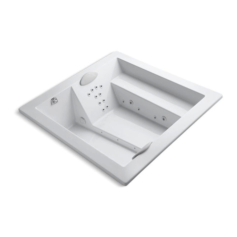
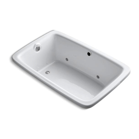
DÉTAILS DE LA MONTURE À BRIDE TYPIQU
MODÈLE DE TYPE INSÉRÉ
VOIR ILLUSTRATION J LONGUEUR LARGEUR DIM DE
PLATEFORME
DIAGONALE
DIM LIGNE DE
BASE DE LA
PLATEFORME
MÉTHODE D’INSTALLATION DE BAIGNOIRE
D’HYDROMASSAGE SUGGÉRÉ
HAUTEUR
JUSQU’AU
REBORD
COMPOSÉ SOLIDIFIANT
CLOISON
PANNEAU DE REVÊTEMENT
IMPERMÉABLE OU PANNEAU EN CIMENT
POTEAU DE
CLOISON EN
BOIS
TUILE
CLOU DE TOITURE
MASTIC
BAIN
1 X 4 (25 X 76MM) TIRANT EN
BOIS PLEINE LONGUEUR
BOUTON DES JETS DE LA
POMPE MARCHE-ARRÊT
BOUTON POUR CHANGER
L’INTENSITÉ DE CONTINUE À
ACTION DES VAGUES
BOUTON POUR CHANGER
L’INTENSITÉ DE CONTINUE À
ACTION DES VAGUES
BOUTON POUR CHANGER
L’INTENSITÉ DE CONTINUE À
ACTION DES VAGUES
BOUTON POUR CHANGER
L’INTENSITÉ DE CONTINUE À
ACTION DES VAGUES
BOUTON DES JETS DE LA
POMPE MARCHE-ARRÊT
BOUTON POUR LA
SOUFFLANTE
MARCHE-ARRÊT
BOUTON POUR LA
SOUFFLANTE
MARCHE-ARRÊT
AJUSTER L’INTENSITÉ DE
LA SOUFFLANTE
AJUSTER L’INTENSITÉ DE
LA SOUFFLANTE
AJUSTER L’INTENSITÉ DE
LA SOUFFLANTE
AJUSTER L’INTENSITÉ
DU DÉBIT DES JETS

†NOTE : L’espace de plateforme des modèles chemisés MIRBD6032(LorR), MIRED6030(LorR), MIRED6032(LorR) &
MIRPR6032(LorR) ne reflète pas l’espace sous la baignoire.
Installation recommandée avec robinets installés au mur seulement.
DANGER : RISQUE DE CHOC ÉLECTRIQUE! Connectez seulement un circuit
séparé protégé par un disjoncteur de fuite à la terre (DDFT)
L’installation doit permettre l’accès à la pompe/moteur pour son entretien.
1. Installez les raccords d’évacuation/ trop-plein de la baignoire selon les instructions offertes.
2. Construisez le cadrage de support sur tous les côtés de la baignoire, permettant une ouverture d’accès 16” X 20”
pour le service de la pompe/moteur des modèles de baignoire d’hydromassage, de bain d’air et de massage total.
3. INSTALLATION PLATEFORME / PÉNINSULAIRE - La surface de la plateforme peut être de n’importe quelle largeur.
Tenez compte de l’épaisseur du panneau de revêtement et de tuile ou autre matériel de surface entre la plateforme
(voir l’illustration « Hauteur du rebord ») et le dessous du rebord de la baignoire.
4. INSTALLATION EN ALCÔVE / COIN - Des tirants de support en bois de 1” X 4” doivent être attachés aux murs
environnants à la hauteur recommandée. Si vous utilisez une chemise, veuillez-vous référer aux instructions
d’installation de chemises offertes avec ce produit. NOTE : Les installations en alcôve et de coin pourraient demander
l’utilisation d’un ensemble de bride à tuile (Pièce# PFTLK and PFTLKC) pour empêcher l’eau de pénétrer le panneau
de revêtement. Après avoir terminé le cadrage, mettez-le produit en place pour vérifier son ajustement et s’assurer
qu’il peut être mis à niveau correctement. (Avertissement : si la baignoire n’est pas à niveau, (utilisez la surface de
plateforme pour vérifierle niveau) l’eau ne drainera pas correctement.) Veuillez-vous référer à la page 4 des instructions
d’installation et de cadrage pour voir le diagramme.
AVERTISSEMENT : Ne jamais supporter la baignoire par le rebord-plateforme ou les tirants, puisque ceci pourrait
rendre le produit défectueux et annuler la garantie. Nivelez et remplissez la baignoire d’eau et testez-la pour tester son
opération et son drainage approprié ou des fuites potentielles en raison d’endommagements lors de la manutention.
Retirez la baignoire de son cadrage.
5. La baignoire DOIT être supportée à partir de son dessous et non par le rebord. Le rebord ne devrait que se reposer
sur la surface de la plateforme ou des tirants de support. Le dessous de la baignoire devrait être supporté par un
composé de fixation, tel que du ciment ou du mortier (les matériaux à séchage rapide ne sont pas recommandés en
raison de rétrécissement excessif). Une feuille de plastique, en dessous et au-dessus du composé, est recommandée
en tant que barrière. La baignoire devrait être mise en place (ne pas manipuler la baignoire hydromasseuse par la
tuyauterie) lorsque le composé est encore malléable et qu’il s’ajustera au-dessous de la baignoire. La baignoire devrait
être descendue jusqu’à ce que le rebord de la baignoire touche le cadre. Il ne devrait qu’entrer à peine en contact
avec la surface de la plateforme finie ou les tirants de support. Il pourrait être nécessaire de remplir partiellement la
baignoire avec de l’eau pour aider la descente de la baignoire.
6. Vérifiez que le produit est à niveau en vérifiant la surface de la plateforme de la baignoire.
7. Placez le robinet et les lignes d’alimentation aux endroits désirés. Si vous installez le robinet et les lignes d’alimentation
sur la plateforme de la baignoire, marquez l’emplacement en premier, choisissez une scie-cloche de taille appropriée,
et percez des trous de départ à partir du côté acrylique du produit. Percez les trous de robinet et d’alimentation à
partir du côté acrylique du produit.
8. Connectez les lignes d’alimentation d’eau et le trop-plein.
9. Branchez le fil de la pompe dans une prise dédiée de 120V/20A DDFT pour alimenter d’électricité pour alimenter le
système. Le fil et la prise est expédiée avec votre système.
10. Après avoir effectué les connexions de plomberie et électriques, la baignoire devrait être nettoyée de saletés et de
débris. Suivez les instructions de « Nettoyage et entretien » dans ces instructions.
11. Pour les installations en coin / alcôve, assurez-vous de laisser un espace d’expansion entre le panneau de revêtement
et la plateforme de la baignoire en plus du revêtement de tuile ou autre matériel et la plateforme de la baignoire.
12. Les entretoises de bois doivent rester en place mais peuvent être coupés pour l’installation du robinet. Les coins qui
ont été coupés doivent être supportés par un 2 X 4 au plancher.
8
DANGER: RISK OF ELECTRICAL SHOCK! Connect only to a separate
circuit protected by a ground fault circuit interrupter (GFCI)
Installation must provide access for servicing pump/motor.
1. Install tub waste/overflow fitting according to instructions provided.
2. Construct support framing on all sides of the tub, allowing for a 16" X 20" access opening for servicing the
pump/motor on whirlpool, air bath and total massage models.
3. DECK / PENINSULAR INSTALLATION - Deck surface can be any width. Allow for the thickness of the wall
board and tile or other surface material between the deck (see “Height to Lip” illustration) and underside of the
tub lip.
4. ALCOVE / CORNER INSTALLATION - Wooden 1" X 4" support stringers must be attached to surrounding walls at the
recommended height. If you use a skirt, refer to the specific skirt installation instructions provided with that
product. NOTE: Alcove and corner installations may require the use of a Tile Flange Kit (Part# PFTLK and PFTLKC) to
prevent water from penetrating the wall board. After the framing is complete, set the product in place to check the fit
and make certain that it can be properly leveled. (Caution: if the tub is not level (use the deck surface for checking
the level) water will not drain properly.) Reference page 4 of Installation and Framing instructions for diagram.
WARNING: Never support the tub by its deck-lip or stringers, as this could result in product failure and void the Warranty.
Level and fill the tub with water and test it for proper operation and drainage or possible water leaks due to transit-
handling damage. Remove the tub from its framing.
5. The tub MUST be supported from the tub bottom and not the tub lip. The lip should only rest on the finished deck
surface or support stringers. The tub bottom must be supported by a setting compound such as cement or mortar
(fast cure materials are not recommended due to excessive shrinkage). A sheet of plastic film, both under and on the
top of compound is recommended as a barrier. The tub should be set in place (do not handle the whirlpool by the
piping) while the compound is still soft and that the compound will conform to the tub bottom. The tub should be
worked down until the lip of the tub touches the frame. It should just barely make contact with the finished deck
surface or support stringers. It may be necessary to partially fill the tub with water to aid in properly setting the tub.
6. Verify that the product is level by checking the tub deck surface.
7. Place the fill spout and supply lines at your desired location. If you areinstalling the spout and supply lines on the deck
of the tub, mark the location first, select a properly sized hole saw, and drill pilot holes from the acrylic side of the
product. Drill the spout and supply line holes from the acrylic side of product.
8. Connect the water supply lines and the waste overflow.
9. Plug the pump cord into specified dedicated 120V/20A GFCI outlet to supply electrical power to the system. The cord
and the plug is shipped with your system.
10. After plumbing and electrical connections have been made the tub should be cleaned of dirt and debris. Follow
“Cleaning and Maintenance” instructions in these instructions.
11. For Corner/ Alcove installation, be certain to allow for an expansion gap between wall board and tub deck
as well as between tile or other water material and tub deck.
12. Wooden braces must stay in place but can be cut for faucet installation. Corners that have been cut need to be
supported by a 2 X 4 to the floor.
†NOTE: Deck space on the MIRBD6032(LorR), MIRED6030(LorR), MIRED6032(LorR) & MIRPR6032(LorR) skirted models
does not reflect spacing under the tub.
Recommend installation with wall mounted faucets only.
“L”
LENGTH
“W”
WIDTH
“Y”
DIAGONAL
DECK DIM
“Z”
BASE LINE
DECK DIM
SKIRTED MODEL
SEE ILLUSTRATION J
MIRBDA6032(LorR), MIRBDS6032(LorR), MIRBDT6032(LorR), MIRBDW6032(LorR) 60" 32" 7"†14"†
MIREDA6030(LorR), MIREDS6030(LorR), MIREDW6030(LorR) 59-3/4" 29-3/4" 3"†8-1/4"†
MIREDA6032(LorR), MIREDS6032(LorR), MIREDW6032(LorR) 59-3/4" 31-3/4" 3-1/4"†7-1/2"†
MIRPRA6032(LorR), MIRPRS6032(LorR), MIRPRT6032(LorR), MIRPRW6032(LorR) 60" 32" 8"†15-1/2"†
INSTALLER UNE BAIGNOIRE OVALE AVEC UN MODÈLE
La section arrière du manuel d’installation contient les instructions de découpage ovale. Utilisez un crayon et un mètre ruban
pour planifier les coordonnés et dessiner la découpe. Prenez soin de placer la baignoire soigneusement dans la découpe
de la plateforme, parce que la baignoire pourrait se briser et les limitations de la garantie qui s’ensuivent deviendraient
nulles. Pour d’autres questions sur l’installation de votre baignoire, veuillez consulter « Procédures d’installation » ci-haut
ou appelez le service à la clientèle au 800-221-3379.
TESTER LA BAIGNOIRE
1. L’installation n’est pas terminée jusqu’à ce que la baignoire soit testée avec de l’eau.
Toutes les baignoires sont testées pour leur fonctionnement à l’usine et certifié contre les fuites. Le transport et la
manipulation pourrait causer des fuites. Il est nécessaire de tester la baignoire tandis qu’on peut encore l’accéder de
chaque côté.
2. L’unité devrait être testé tel quel et pour son fonctionnement.
a. Scellez le drain et remplissez la baignoire au niveau normal.
b. Laissez la baignoire pendant 30 minutes après l’avoir remplie et inspectez toute la tuyauterie pour des fuites.
c. Après avoir effectué le test précédent, Mettez en marche chaque pompe et vérifiez les fuites. Inspectez les
raccords-union autour de la pompe de nouveau. Si les fuites des raccords-union persistent après avoir été resserrés;
desserrez les raccords-union et assurez-vous que l’anneau en forme de O est correctement ajusté.
3. Si la pompe ne fonctionne pas;
a. Vérifiez le disjoncteur pour s’assurer qu’il est alimenté.
b. Vérifiez les connexions au niveau de l’interrupteur et des bornes de la pompe pour s’assurer qu’ils soient
correctement attachés.
4. N’opérez pas de pompe ou de réchauffeur à moins que la baignoire soit remplie 1 po sous le trop-plein. Les
endommagements causés par une pompe fonctionnant à sec ne sont pas couverts par la garantie.
Ne pas effectuer ces tests immédiatement après l’installation de la baignoire met l’installateur à risque des coûts de
réparations ultérieures.
NETTOYAGE ET ENTRETIEN
Les bains d’air sont équipés avec un cycle de nettoyage et de purge automatique
Les bains d’air ont un cycle de purge et de nettoyage préprogrammé pour expulser le restant d’eau des canaux d’air. Il
s’active les 20 minutes après que le bain d’air est désactivé et souffle pendant 2 à 3 minutes. Après le cycle terminé, il
s’éteindra automatiquement. Il n’est rien d’alarmant si vous entendez un son de ventilation provenant de la baignoire
après qu’elle soit éteinte. Le bruit que vous entendez n’est que le cycle de nettoyage en cours. Il est recommandé
d’activer le bain d’air régulièrement pour purger l’eau des canaux d’air lorsque la baignoire est utilisé en tant que bain ou
douche seulement. Le cycle de purge ne s’active que lorsque la soufflante est utilisée.
Le système de circulation de pompe et tuyauterie devrait être activé avant la première utilisation et sur une base mensuelle
lorsque le produit est utilisé normalement. Les procédures ci-dessous sont recommandées pour le nettoyage:
• NE PAS ACTIVER LORSQUE LA BAIGNOIRE HYDROMASSEUSE EST VIDE. Remplissez la baignoire avec de l’eau
chaude 2-3 pouces au-dessus des jets et ajoutez 2-3 cuillères à thé de détergent à faible écume tel que du détergent
à lave-vaisselle.
• Activez l’hydromassage et laissez pendant 10 minutes.
• Drainez la baignoire complètement.
• Remplissez la baignoire avec de l’eau froide au-dessus des jets.
• Activez l’hydromassage et laissez pendant 5 minutes.
• Drainez la baignoire complètement.
NE PAS UTILISER DE NETTOYANTS ABRASIF puisqu’ils égratignent et ternissent la surface de l’acrylique.
Le platre peut être retiré à l’aide d’un bâtonnet de bois éguisé. NE PAS UTILISER DE GRATOIRS, BROSSES EN FIL DE
MÉTAL OU AUTRES OUTILS ABRASIFS. Un détergent doux éliminera les débris de construction. Les débris les plus
tenaces peuvent être retirés avec de l’alcool dénaturé, ou du nettoyant Clorox Soft Scrub®. Les petites égratignures et
zones ternies peuvent être remises en étant à leur éclat original à l’aide d’un composé de nettoyage de type automobile
tel que DuPont White Polishing Compound®.
INSTRUCTIONS D’OPÉRATION
1. Remplissez la baignoire jusqu’au moins 3 pouces au-dessus des jets avant d’activer la pompe.
2. La soufflante du bain d’air et/ou la pompe d’hydromassage s’active en appuyant sur les boutons du panneau de
commande. Ne pas appuyer sur l’interrupteur à plusieurs reprises si la fonction d’hydromassage ne s’active pas
immédiatement, puisqu’elle pourrait prendre plusieurs secondes avant que vous la voyez s’activer entièrement. Veuillez
voir les instructions de commande de bain d’air ou de Massage Total à la page suivant pour les fonctions et mode
d’emploi.
3. Si n’importe quel raccord installé par l’usine est retiré; n’opérez pas l’unité. Un risque d’accident pourrait avoir lieu.
4. Ne pas utiliser de bain moussant lorsque vous opérez la pompe d’hydromassage. Ceci pourrait faire mousser la baignoire
excessivement.
5. L’utilisation d’huiles de bain est déconseillée en raison de la difficulté à les nettoyer des systèmes.
6. Les systèmes à air et d’hydromassage sont raccordés de façon à ce que l’eau draine de la tuyauterie facilement.
7. Il n’y a aucune partie ayant besoin d’entretien par l’utilisateur sous la baignoire.
MODÈLE CHEMISÉ
VOIR ILLUSTRATION J LONGUEUR LARGEUR DIM DE
PLATEFORME
DIAGONALE
DIM LIGNE DE
BASE DE LA
PLATEFORME
This manual suits for next models
79
Table of contents
Other Mirabelle Bathtub manuals
Popular Bathtub manuals by other brands

CLEVERSPA
CLEVERSPA 10001 instruction manual

Kohler
Kohler K-18347X Installation and care guide

Sterling Plumbing
Sterling Plumbing ENSEMBLE 71121122 Specifications

Kohler
Kohler K-1209-HL Roughing-In Guide

TEIKO
TEIKO VZP2 ASSEMBLY AND USER'S MANUAL INSTRUCTIONS

Villeroy & Boch
Villeroy & Boch Combipool operating instructions