MirroCraft 1685 User manual

$9.95
69877_36635 4/4/11 10:17 PM Page A

1
TABLE OF CONTENTS
Introduction . . . . . . . . . . . . . . . . . . . . . . . . . . . . . . . 2
Boating Safety . . . . . . . . . . . . . . . . . . . . . . . . . . . . . 3
Labels . . . . . . . . . . . . . . . . . . . . . . . . . . . . . . . . . . . 4
BIA Tag. . . . . . . . . . . . . . . . . . . . . . . . . . . . . . . . . . 4
Safety Recommendations . . . . . . . . . . . . . . . . . . . . . 5
Systems and Components . . . . . . . . . . . . . . . . . . . . . 6
Mounting Aftermarket Equipment . . . . . . . . . . . . . 17
Maintenance . . . . . . . . . . . . . . . . . . . . . . . . . . . . . 22
Care and Cleaning . . . . . . . . . . . . . . . . . . . . . . . . . 23
Winterization and Storage . . . . . . . . . . . . . . . . . . . 25
Launching . . . . . . . . . . . . . . . . . . . . . . . . . . . . . . . 27
Fueling Recommendations . . . . . . . . . . . . . . . . . . . 28
Glossary of Terms . . . . . . . . . . . . . . . . . . . . . . . . . 29
69877_36635 4/4/11 10:17 PM Page 1

2
INTRODUCTION
Congratulations on your purchase of a high quality aluminum boat.
All MirroCraft boats meet or exceed all U.S. Coast Guard safety standards
relating to load, horsepower, capacity, flotation, electrical, steering, ventilation,
and fuel system on the date of manufacture.
This manual supplies you with information about your new MirroCraft boat and
the different systems and components that are a part of your boat. Please read
this manual and familiarize yourself with your boat and components of your
boat. Read all manuals that cover the individual components of your boat such
as pumps, steering, stereo, engine, and other items that may be standard or
optional on your particular model.
Please fill out all warranty cards that come with your boat at the time of pur-
chase and return to the manufacturers as specified on the warranty cards. If you
have a problem with a specific component in your boat please contact the
manufacturer of that component such as pump or stereo which is covered by a
separate warranty. If you are not satisfied with the response please contact your
local MirroCraft dealer to assist you.
69877_36635 4/4/11 10:17 PM Page 2

3
BOATING SAFETY
Please read your manual and familiarize yourself with the operation of your
MirroCraft boat before getting under way. It is recommended that you take a
boating safety course to familiarize yourself with the safe operation of your new
boat. This manual contains four levels of safety precautions. Please read and
understand these precautions.
DANGER:
Immediate hazard which will result in severe
personal injury or death.
WARNING:
Hazards or unsafe practices which could result in
severe personal injury or death.
CAUTION:
Hazards or unsafe practices which could result in
minor injury or product or property damage.
NOTICE:
Information which is important to proper operation or
maintenance, but is not hazard related.
69877_36635 4/4/11 10:17 PM Page 3

4
LABELS
There are labels at various locations on your boat. Please do your part in
reading these labels. MirroCraft has posted these labels so you may have a safe
boating experience. If there are any labels missing please contact your local
Mirrocraft dealer to have them replaced.
Below are a few examples of the labels which may or may not be on your boat
when you purchased it. Below are samples of some of the labels that may have
come with your boat.
BIA TAG
The BIA capacity tag is very important. It specifies the number of persons,
maximum horsepower of your model boat and maximum load capacity.
Below is an example of a BIA tag.
WARNING:
Never remove your BIA tag.
69877_36635 4/4/11 10:17 PM Page 4

5
SAFETY RECOMMENDATIONS
The following recommendations should be followed for your protection and to
have a safe boating experience.
•Never operate a boat while under the influence of alcohol or drugs.
•Check with your MirroCraft dealer for the proper safety equipment
that is required for the size of boat that you have purchased.
You may also contact the U.S. Coast Guard’s toll free safety hotline.
U.S. COAST GUARD 1-800-368-5647
•Regularly inspect your boat, engine and all safety equipment to keep it
in a safe operating condition.
•Keep lifesaving equipment and fire extinguisher available and
accessible at all times. All passengers should know the location and
how to us them.
•Always operate your boat with consideration, courtesy and common-
sense. Contact your local Coast Guard for a copy of navigational rules
in your area.
•Always be aware of the weather when you go boating. Check local
forecasts to monitor the local weather.
•When under way, all occupants should sit in a forward facing position
with the swivel seats locked in a forward position.
•Never overload your boat. Check your capacity plate for proper
weight, horsepower and number of persons allowed.
•Always turn off engine before using swimming platform.
•Extinguish all flames when refueling your boat. If any fuel is spilled in
the boat clean up immediately.
•In case of swamping or flooding of your boat
(STAY WITH YOUR BOAT).
DANGER:
Failure to turn off engine could result
in death or serious injury.
69877_36635 4/4/11 10:17 PM Page 5

6
SYSTEMS AND COMPONENTS
This section covers the various systems in your MirroCraft boat. It supplies
illustrated information on your boat. Depending on the model of boat and the
options that are installed you may or may not have all the equipment described.
If you have any questions please consult your local MirroCraft dealer.
Integrated Performance Tabs
are used to enhance boat
performance and should
only be adjusted by your
local Mirrocraft dealer.
Livewells and Baitwells
A livewell is standard on some boats. The livewell on the boat that you have
purchased may look different than the diagrams below, but they all operate on
the same principles. A typical livewell consists of the following components.
69877_36635 4/4/11 10:17 PM Page 6

7
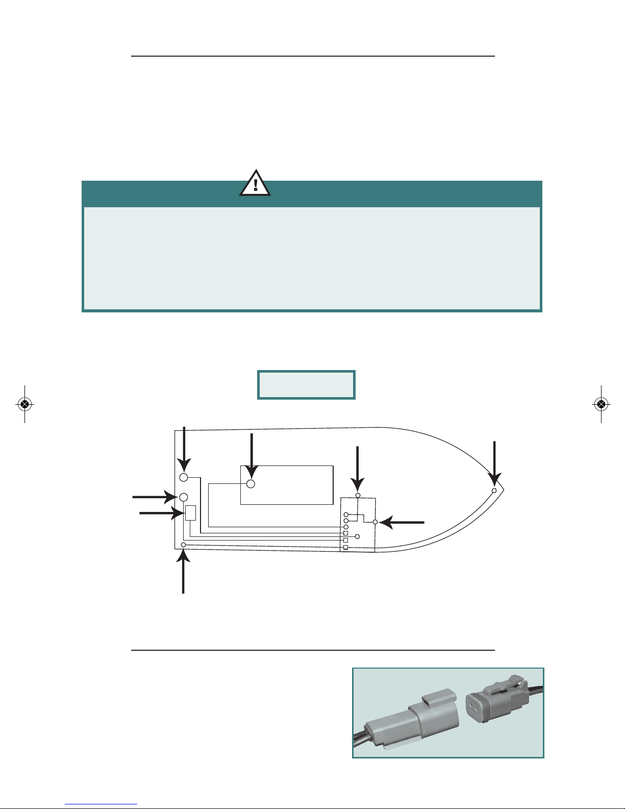
Aerator head: Used to bring fresh water into the livewell or baitwell. The flow
rate may be adjusted by turning the head to the right to decrease the
flow and to the left to increase the flow. (Do not turn aerator head off
completely when pump is running)
Drain: The drain fitting is connected to a fitting that exits through the stern of
the boat. To drain the livewell or baitwell remove standpipe.
Standpipe: The standpipe is inserted into the drain. It is used to control the
depth of water in the livewell or baitwell. The standpipe may be
trimmed to control the depth of water in the livewell or baitwell. If you
experience livewell overflow, trim standpipe.
Overflow: Some models due to the size of the livewell have an overflow mounted
on the side of the livewell. This is just another way to control the
amount of water in the livewell.
Livewell pump: The livewell pump supplies fresh water to the livewell or baitwell.
The pump is usually located at the stern of the boat below the water-
line. The pump is controlled by a fused switch on the switch panel.
Livewell Light: The light is waterproof and is mounted in the side of the livewell
on some models. The light is controlled by a fused switch marked either
courtesy light or accessory.
To use your livewell, first insert the standpipe in the drain. Next go to switch
panel and turn on proper switch. Let livewell fill to top of standpipe and then
either turn off or let run continuously. To decrease the water flow you may
adjust the aerator head by turning to the right. (The boat must be in the
water before running the pump.)
If your livewell or baitwell drain becomes plugged, you can try to force water
through the fitting with a water hose to flush it out. If your livewell or baitwell
pump fails to operate, check your fuses and also the electrical connection of the
pump. If you still have problems with your pump check the instructions that
came with your boat before contacting your local dealer.
NOTICE:
If water in the livewell or baitwell freezes it could
cause the hoses to burst and the pumps to break.
Ensure all water is out of system.
69877_36635 4/4/11 10:17 PM Page 7

8
Recirc/Timer Kit: This kit consists of a pump, aerator head (Figure B-1) and
timer switch panel (Figure B-2). This switch panel has an inline fuse on the red
wire.
• The panel has three positions on the front of it.
• The recirc kit may be installed on a livewell or on a baitwell depending
on the model and options on the boat you own.
•To use the recirc pump you must first fill the livewell or baitwell with
fresh water. Do this by turning on main livewell or baitwell pump.
When water level reaches the top of standpipe, turn off pump and then
start recirculation pump in the mode that you want. Livewell or baitwell
must be full before starting recirc pump.
On - Turns pump on continuous run
Off - Turns pump off
Off - On - Intermittent operation which typically turns the recirc pump
on and off at three minutes intervals.
Figure B-1
Figure B-2
69877_36635 4/4/11 10:17 PM Page 8

9
Fuel Tank
Courtesy Light
Blue/Black
Horn
Red/Black
Live Well Pump
Brown Orange Stripe/Black
Sending Unit
Pink/Black
Bow Light
Gray/Black
Bilge Pump
Brown/Black
Battery
Red/Black
Stern Light
Gray Blue Stripe/Black
Electrical System
This section covers all standard 12 volt DC components on your MirroCraft
boat. The electrical system in your boat is a 12 volt DC ground. All
components must be grounded directly to the battery negative terminal or
to a grounding block that is connected to the negative battery terminal.
NOTICE:
Failure to properly ground your accessories could
seriously damage your aluminum hull through electrolysis.
Insulate all unused power leads when your boat is
in use to prevent sparking and electrolysis.
The diagram below (Figure E-1) shows the basic wiring of a MirroCraft boat.
The model you have may or may not be exactly the same.
Figure E-1
Deutsch Connectors
For your convenience some models have
Deutsch Connectors on the electrical
components. Please see your local Mirrocraft
dealer if these components need servicing.
69877_36635 4/4/11 10:17 PM Page 9

10
Navigation Lights
The navigation lights are controlled by a three-way switch. This allows you to
select the following lighting. One position turns on the stern light. (This should
be on whenever you are anchored at night) Another position allows both the
bow and stern to be turned on for cruising at night. The center position turns
off the stern and bow light. To install the bow and stern light poles, line up the
slots and insert pole in base.
CAUTION:
Always test your navigation lights before heading out.
Marine Stereo
Due to the different options available all stereos come with a separate manual
that will explain all operations.
Livewell and Bilge Pump
The pumps are each controlled by a separate switch on the switch panel. If the
pumps fail to work, first check the fuse or circuit breaker. If that is okay, check
the pumps for any kind of blockage or loose wires. To clean pumps, refer to
manuals that came with your MirroCraft boat.
69877_36635 4/4/11 10:17 PM Page 10

11
Courtesy Light
The courtesy lights are either wired to the courtesy light switch or the accessory
switch, depending which model you purchased. Both are supplied with a fuse or
circuit breaker. If the lights do not work, first check the fuse or circuit breaker
and then check the bulbs and connections.
Horn
The horn is connected to a push button on the switch panel that is protected
with a fuse or circuit breaker.
NOTICE:
Not all MirroCraft boats have horns installed. Check with
Coast Guard regulations to see if you are required to
have a horn or some other signaling device.
Seat Bases
All seat bases are factory installed in locations that have been reinforced to han-
dle the stresses associated with operating your boat. Check seat fasteners prior
to using your boat.
WARNING:
Do not attempt to move or install new bases without
contacting your local MirroCraft dealer.
69877_36635 4/4/11 10:17 PM Page 11

12
Ski Pylon
If your MirroCraft boat is supplied with a ski pylon it is very important to make
sure that it is completely assembled according to manufacturer’s instructions
that came with your boat.
DANGER:
To avoid serious injury, death or boat damage from ski
pylon failure. Ski pylon must be secured to base. Do not
use with any equipment which is tied to the tow rope
such as inner tubes, aquaplanes, etc.
Instrumentation
A typical instrumentation panel consists of the following items (Figure D-1).
Your MirroCraft boat may or may not include all of these components.
Figure D-1
69877_36635 4/4/11 10:17 PM Page 12

13
Fuel Gauge
Shows the amount of fuel remaining in the tank. To get an accurate reading the
boat should be in a level position. Always keep track of your fuel consumption.
As a rule of thumb, don’t let your fuel levels go below one third of a tank before
refueling due to the accuracy of the gauge while the boat is on plane.
Tachometer
The tachometer displays the revolution per minute (RPM) of the engine. If you
have any problems with the tachometer please contact the manufacturer of the
gauge.
Speedometer
The speedometer shows the boat speed in miles per hour (MPH). For the
speedometer to read accurately the pickup tube must be in the down position
for running. The pickup tube must be kept clean at all times. The tube is
located on the outside bottom edge of the transom or on engine. The tube
must be tilted up for trailering to avoid damage.
Voltage
The voltage displays the condition of the battery. It should normally read
between 11–14 volts when the engine is running.
69877_36635 4/4/11 10:17 PM Page 13

14
Power Trim Gauge
This gauge shows the position of the engine in relation to the running
performance. Proper trim will be indicated by the performance of the boat.
Accessory Plug
CAUTION:
Socket is to be used for electrical accessories only. It is not
to be used as a lighter plug. If it is used as a lighter plug
it will melt and cause a short circuit.
Steering
Because of all the different options on steering control please read the manual
and instructions that came with your MirroCraft boat.
Motor Trim/Tilt
Because of all the different engine options, please read the manual and instruc-
tions that came with your Mirrocraft boat. When tilting the motor, ensure all
seats and equipment (ie. seats, ski pylon) are stowed or engine damage could
result.
69877_36635 4/4/11 10:17 PM Page 14

15
Fuel System
This section is for boats with internal tanks only. On boats with portable tanks
please follow manufacturer’s recommendations. The fuel system is designed to
meet or exceed federal requirements of the U.S. Coast Guard at the time of
manufacture. The fuel system has been inspected and pressure tested at the
factory before shipped. Also, all components of the fuel system must pass tests
and inspections by the manufacturers. The fuel system consists of the following
components:
Fuel Fill: The fuel fill is labeled Gas or Fuel. Be sure to use the fuel
recommended by the engine manufacturer.
Fuel Vent: The vent allows air to escape from the fuel tank when filling. When
tank is about full, a small amount of fuel may be discharged from vent.
Fuel Pickup Line: This line connects the fuel tank to the engine. Follow engine
manufacturer’s recommendation for the fuel filter required, if any.
Fuel Tank: All fittings and connections on the fuel tank are accessible for
inspection; contact your dealer for the location of the inspection plates and
hatches.
NOTICE:
You should have the fuel system inspected once a year.
The diagram (figure F-1) shows a basic fuel system.
Figure F-1
69877_36635 4/4/11 10:17 PM Page 15

16
Battery
Battery (Cranking): The cranking battery on your boat is designed to start your
boat and power all your electrical equipment. Do not use your cranking battery
to power a trolling motor because it is not designed for the steady current draw
that a trolling motor requires.
Battery (Deep Cycle): The deep cycle battery is designed for the constant
draining and recharging required powering a trolling motor. Do not use a deep
cycle battery for a cranking battery unless it is a combination deep cycle, starting
battery.
NOTE: It is always recommended to have separate batteries for cranking and
trolling.
IMPORTANT: Follow the battery manufacturer’s instruction on proper charging
and maintenance.
IMPORTANT: Only mount batteries in approved battery boxes or trays that
have been installed by the manufacturer.
WARNING:
Batteries produce gases when charging and can explode.
Keep all flames and sparks away from battery when charging.
69877_36635 4/4/11 10:17 PM Page 16

17
MOUNTING AFTERMARKET EQUIPMENT
Trolling Motor (gas)
Always take into account the weight of the trolling motor into the total weight
capacity of the boat specified on the BIA tag on your boat. Mounting a trolling
motor on the back of your boat may affect the balance and performance of your
boat.
Trolling Motor (electric)
Always take into account the weight of the trolling motor into the total weight
capacity of the boat specified on the BIA tag on your boat.
Graphs and Transducers
Always make sure that the transducer mounting plate does not extend past the
bottom of the hull as this will affect the performance of your boat. Please see
diagrams below.
Incorrect
Transducer will affect the
performance of boat-it extends
past bottom of boat.
Correct
Transducer does not extend
past bottom of boat.
NO OK
69877_36635 4/4/11 10:17 PM Page 17

18
Bilge Pump
The bilge pump is used to remove water that accumulates in the bilge area. The
switch that controls the pump is mounted on the switch panel and is protected
by a circuit breaker or fuse. Some boat models are equipped with an automatic
bilge switch. When water rises to a certain level in the bilge, the pump will turn
on automatically and when the water is pumped out, the float switch shuts off.
The bilge pump can also be turned on manually at the switch panel. To clean
your bilge pump refer to the manufacturer’s instructions that came with your
boat.
IMPORTANT: Check your bilge pump every time you use your boat and make
sure that the area around the pump and float switch is kept clean.
WARNING:
If oil or fuel is spilled in the bilge do not turn on pump.
Contact your local dealer for advice in removing the gas or oil.
Canvas
Some Canvas is installed using lift-the-dot snaps. Please see picture for proper
removal of snap.
Lift Here
69877_36635 4/4/11 10:17 PM Page 18

19
Bow Trolling Systems
Your MirroCraft boat may be equipped with one of the following trolling
systems:
Deluxe bow trolling panel (Figure T-1): The deluxe panel has the option of
allowing a 12 volt or 24 volt trolling motor to be installed on your boat.
To be used for 24 volts both batteries (A + B) must be connected to the
trolling harness. The plug must be wired for 24 volts according to the
markings on the plug. To be used for 12 volts battery (A) must be con-
nected to the trolling harness and the plug must be wired for 12 volts
according to the markings on the plug.
Figure T-1
69877_36635 4/4/11 10:17 PM Page 19
Table of contents