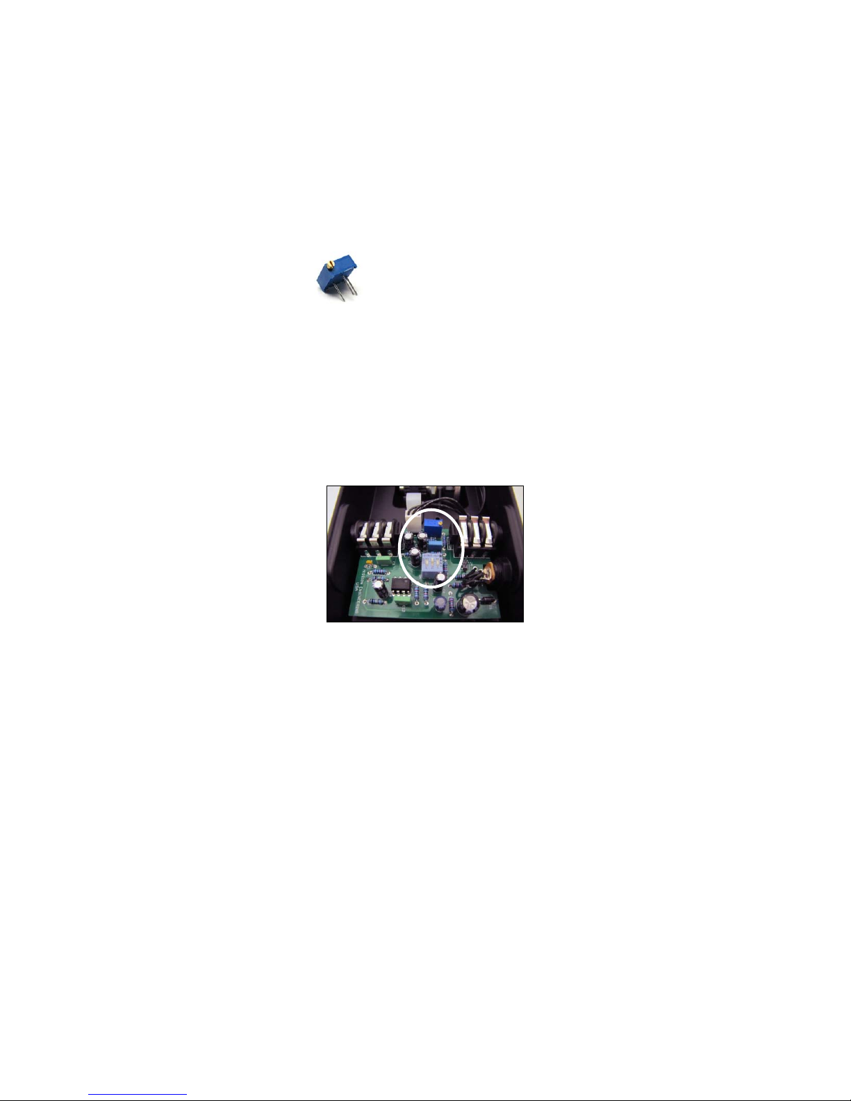
manuals.online logo
Brands
  1. Home
  2. •
  3. Brands
  4. •
  5. Mission
  6. •
  7. Music Pedal
  8. •
  9. Mission VM-PRO User manual

Mission VM-PRO User manual

ALL external connections are removed before opening the
pedal. To reduce the risk of damage, avoid touching any
other components in the pedal. Do not attempt to use any
power supply with specifications other than those listed in
this manual. Check all cables and power supplies for signs of
damage before use. Do not connect damaged power supplies
or cables. Replace cables or power supplies showing any signs
of damage.
The VM-PRO™ can be powered by an external power supply
in place of the internal 9v battery. The power input is center
pin negative with a 2.1mm connector. The circuit is protected
against reversed polarity to avoid possible damage by
accidentally connecting a center pin positive supply, however,
the pedal will not work unless the correct polarity power is
supplied. The VM-PRO™ supports input power in the range
9VDC – 18VDC.
WARNING! Do not use a power supply exceeding 18VDC
output. This will invalidate the warranty and may damage the
pedal.
In most cases a 9VDC supply will be sufficient, but using a
higher input voltage will increase the clean headroom of the
buffer amplifier. If you are using the pedal with a very hot
input such as active pickups, using an increased input voltage
can be used as an alternative or in addition to using the active/
passive switch to avoid distortion.
The reverse is also true; by using a hot input and keeping
the input supply voltage at 9VDC , the pedal can be driven
into slight distortion at maximum volume. This can actually
be preferred in some cases as the pedal can then be utilized
as a mild overdrive. Experiment with different settings to see
what sounds best to you, and meets your particular sonic
requirements.
Switch
The switch block is an internal three-position switch located
in the center of the circuit board and looks similar to the
picture in Figure 1. Further information on the switch settings
and their defaults is available in the VM-PRO™ User Guide.
IMPEDANCE SWITCH
The impedance is controlled using switch 3 on the internal
switch block. Some effect pedals, in particular vintage fuzz
Inoduion
Congratulations on your purchase of the Mission VM-PRO™
Volume Pedal. We recommend that you take a few moments
to read through the VM-PRO™ User Guide to become familiar
with the basic functions of the VM-PRO™ before proceeding
with this Advanced Configuration Guide.
The Advanced Configuration Guide includes additional
information on the features of the VM-PRO™, as well as some
tips and tricks on customizing it for your particular rig.
Pment
In general it is recommended to start with the VM-PRO™ first
in the signal chain with your instrument connected directly to
the input with a good quality cable. This will give the buffer
it’s best opportunity to deal with any mismatches between
the high impedance guitar pickups, and low impedance
devices further down the chain. This is especially important
with low output single coil pickups. When placed at the start
of the chain, the volume pedal will act in a similar fashion
to the volume control on the instrument. Overdriven signals
will clean up when rolling back the volume. Echo repeats
and reverb tails from devices further down the chain will be
preserved when using volume swells.
Alternatively, the VM-PRO™ can be placed at the end of
the signal chain. The last effect on a pedal board should be
plugged into the input and then the output into the amplifier.
In this case the pedal will act more like a master volume
control for the entire pedal board. This placement can also be
useful if using a very long cable run from the pedal board back
to the amp. The VM-PRO™ will act as a line driver preventing
the loss of signal response due to the load of long cable. In
most cases, there should not be any issues with using more
than one buffered device in a single chain, so using the VM-
PRO™ with another buffer present is OK. In general when
using multiple buffers, aiming for one buffer at the beginning
and another as close as possible to the end of the chain will
be a good place to start.
The above recommendations are not exclusive. Experiment
with different placements to determine what works best for
your particular rig.
pow
WARNING! Do not attempt to remove the baseplate or
change the internal battery while the pedal is connected to
an external power supply and/or amplifier. Make sure that
Buffered
Volume Pedal
VM-PrO
Adnd
ConfigurAtion
Guide
MISSION
ENGINEING
Figure 1.
Figure 2.
To adjust the trim-pot insert a small electronics or jewelers
flat head screwdriver into the adjustment screw. Turning the
screw counter-clockwise will allow some signal to pass at
heel down. This allows the VM-PRO™ to be used as a variable
boost control to blend between a lower volume for rhythm
and a higher volume for lead Turning the screw clockwise
will send more of the signal to ground eventually reaching the
default point at which the signal is completely muted. The
trim-pot is 25 turns end to end, so you may find you need to
turn the screw two or three whole rotations before there is a
noticeable difference. Once you have reached the approximate
volume you need, you can make smaller adjustments to
precisely tune the position to your preference.
WARNING! Do not attempt to remove the baseplate or
change the internal battery while the pedal is connected to
an external power supply and/or amplifier. Make sure that
ALL external connections are removed before opening the
pedal. To reduce the risk of damage, avoid touching any
other components in the pedal. Do not attempt to use any
power supply with specifications other than those listed this
manual. Check all cables and power supplies for signs of
damage before use. Do not connect damaged power supplies
or cables. Replace cables or power supplies showing any signs
of damage.
Mission Enginring Inc.
www.missionengineering.com [email protected]
©Mission Engineering Inc. 2013. All rights reserved.
VM-PRO™
is a Trademark of Mission
Engineering Inc. Trademarks, registered trademarks, product names, logos and other materials
are the property of their respective owners.
Saty
Inruions
Read, Keep & Follow these instructions
Heed all warnings
Clean only with dry cloth
Do not use this apparatus near water
Do not expose the apparatus to dripping or
splashing and ensure that no objects filled with
liquids, shall be placed on the apparatus
 WARNING: To reduce the risk of fire or electric
shock do not expose this apparatus to rain or
moisture
Unplug this apparatus during lightning storms or
when unused for long periods of time
Do not block any ventilation openings. Install in
accordance with the manufacturer’s instructions
Do not install near any heat sources such
as radiators, heat registers, stoves, or other
apparatus (including amplifiers) that produce
heat
Only use attachments/accessories specified by
the manufacturer
Prolonged listening at high volume levels may
cause irreparable hearing loss and/or damage.
Always be sure to practice “safe listening.”
Refer all servicing to qualified service personnel.
Service is required when the apparatus has been
damaged in any way, such as:
- power-supply cord or plug is damaged
- liquid has been spilled or objects have fallen
into the apparatus
- the unit has been exposed to rain or moisture.
- the unit is dropped or the enclosure is
damaged
- the unit does not operate normally or changes
in performance in a significant way
pedals and their clones, expect a high impedance input from
a guitar pickup. It is normally required to place these first in
a signal chain or in a separate loop altogether. The VM-PRO™
can be switched to provide a high impedance output that
effectively emulates a guitar pickup. In this case the guitar
can be plugged into the VM-PRO™ input so that it is buffered.
Then the output from the VM-PRO™ can be connected to the
fuzz pedal and it will appear to the fuzz pedal as if the guitar
pickup is connected directly.
ACTIVE/PASSIVE SWITCH
The Active Passive control is switch 1 on the internal switch
block. The factory default settings assume typical output
passive pickups will be connected to the input of the VM-
PRO™. When using very high output pickups such as some
active devices, there is a possibility that the VM-PRO™’s
buffer amplifier may be driven into slight distortion at full
volume. This can be resolved by switching the Active/Passive
switch to Active. If distortion occurs, you can, if you wish,
leave the switch in the passive position and use the VM-PRO™
as a mild overdrive.
SPARKLE SWITCH
The Sparkle control is switch 2 on the internal switch block.
The factory default is set for a flat frequency response.
Typically at this setting when rolling back the volume, a
slight reduction in high frequencies can be perceived. This is
normal, and for many electric guitar players, the darkening
of the tone at lower volumes is part of their overall sound.
Leave the sparkle switch in the default off position when
this is preferred. When switched on, the Mission Sparkle
switch, adds some brightness to the tone, this is noticeable
in particular when rolling back the volume as it compensates
for the loss of high frequency perception at reduced levels.
The sparkle setting is very useful when using the volume
pedal with other instruments such as acoustic instruments
and keyboards where a darker tone may not be ideal. It’s also
useful when using the pedal as a master volume rather than
an input volume, or gain control.
MINIMUM VOLUME ADJUSTMENT
Every VM-PRO™ is individually calibrated at the factory so
that it is in mute mode at full heel down. In this position, none
of the instrument signal will pass through to the amp and the
output will be completely silent. This setting can be adjusted
using a small internal trim-pot. The trim-pot is located at the
top of the circuit board, and looks similar to the picture in
Figure 2.

Other Mission Music Pedal manuals

Mission EP1-KP User manual

Mission

Mission EP1-KP User manual

Mission Ep1-KP User manual

Mission

Mission Ep1-KP User manual

Mission EP1-KP User manual

Mission

Mission EP1-KP User manual

Mission GC-EXP1 PRO User manual

Mission

Mission GC-EXP1 PRO User manual

Mission VM-PRO User manual

Mission

Mission VM-PRO User manual

Mission VM-PRO User manual

Mission

Mission VM-PRO User manual

Mission SP1-L6H User manual

Mission

Mission SP1-L6H User manual

Mission Pigtronix User manual

Mission

Mission Pigtronix User manual

Mission Expressionator User manual

Mission

Mission Expressionator User manual

Mission EP-11S User manual

Mission

Mission EP-11S User manual

Mission EarthQuaker EQD-1 User manual

Mission

Mission EarthQuaker EQD-1 User manual

Mission VM-1 User manual

Mission

Mission VM-1 User manual

Mission RewAh PRO User manual

Mission

Mission RewAh PRO User manual

Popular Music Pedal manuals by other brands

HEADRUSH Gigboard quick start guide

HEADRUSH

HEADRUSH Gigboard quick start guide

JAM Pedals CTRL BOX quick start guide

JAM Pedals

JAM Pedals CTRL BOX quick start guide

Eden CaliforniWAH quick start guide

Eden

Eden CaliforniWAH quick start guide

Radial Engineering Hot-British V9 user guide

Radial Engineering

Radial Engineering Hot-British V9 user guide

Fender Pinwheel manual

Fender

Fender Pinwheel manual

Positive Grid BIAS DISTORTION product manual

Positive Grid

Positive Grid BIAS DISTORTION product manual

BYOC 10-band graphic equalizer instructions

BYOC

BYOC 10-band graphic equalizer instructions

EarthQuaker Devices Hoof Operation manual

EarthQuaker Devices

EarthQuaker Devices Hoof Operation manual

Electric Druid FilterFX Project Construction guide

Electric Druid

Electric Druid FilterFX Project Construction guide

Heusinkveld Sim Handbrake product manual

Heusinkveld

Heusinkveld Sim Handbrake product manual

aion CRESCENT AMP DISTORTION manual

aion

aion CRESCENT AMP DISTORTION manual

Shure GLXD6 user guide

Shure

Shure GLXD6 user guide

Strymon Volante quick start guide

Strymon

Strymon Volante quick start guide

EBS BLACK LABEL OCTABASS user manual

EBS

EBS BLACK LABEL OCTABASS user manual

Better Music Builder DX-5000 owner's manual

Better Music Builder

Better Music Builder DX-5000 owner's manual

Himmelstrutz Fetto Maximus owner's manual

Himmelstrutz

Himmelstrutz Fetto Maximus owner's manual

Behringer MIDI FOOT CONTROLLER FCB1010 user manual

Behringer

Behringer MIDI FOOT CONTROLLER FCB1010 user manual

CICOGNANI ENGINEERING Pompeii PE603 user manual

CICOGNANI ENGINEERING

CICOGNANI ENGINEERING Pompeii PE603 user manual

manuals.online logo
manuals.online logoBrands
  • About & Mission
  • Contact us
  • Privacy Policy
  • Terms and Conditions

Copyright 2025 Manuals.Online. All Rights Reserved.